JVC VS-DT2000 Instructions Manual
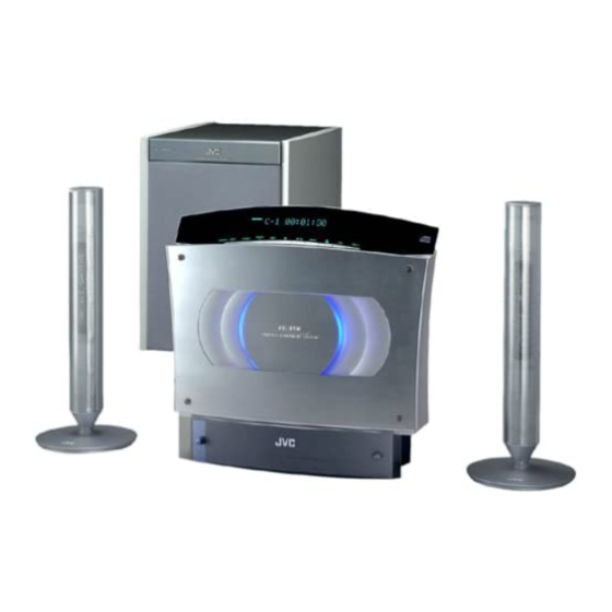
Compact component system consists of ca-vsdt2000, sp-vsdt2000 and sp-pw2000
Hide thumbs
Also See for VS-DT2000:
- Instructions manual (32 pages) ,
- Service manual (69 pages) ,
- Service manual (81 pages)
Table of Contents
Advertisement
COMPACT COMPONENT SYSTEM
SISTEMAS DE COMPONENTES COMPACTOS
SISTEMA DE COMPONENTES COMPACTOS
VS-DT2000
Consists of CA-VSDT2000, SP-VSDT2000 and SP-PW2000
Consiste de CA-VSDT2000, SP-VSDT2000 y SP-PW2000
Consiste em CA-VSDT2000, SP-VSDT2000 e SP-PW2000
CA-VSDT2000 SP-VSDT2000 SP-PW2000
STANDBY/ON
1
2
3
PLAY MODE
4
6
5
REPEAT
7
8
9
FM MODE
10
+
10
BASS
TREBLE
SET
MD/AUX
CANCEL
FM/AM
DISPLAY
DIMMER
SLEEP
CLOCK
OPEN/
COLOR
/TIMER
CLOSE
VOLUME
SP-VSDT2000
COMPACT COMPONENT SYSTEM
CA-VSDT2000
INSTRUCTIONS
MANUAL DE INSTRUCCIONES
INSTRUÇÕES
SP-VSDT2000
For Customer Use:
Enter below the Model No. and Serial No.
which are located either on the rear, bot-
tom or side of the cabinet. Retain this
information for future reference.
Model No.
Serial No.
SP-PW2000
LVT0854-004A
[US, UW]
Advertisement
Table of Contents

Related Manuals for JVC VS-DT2000


Summary of Contents for JVC VS-DT2000
- Page 1 COMPACT COMPONENT SYSTEM SISTEMAS DE COMPONENTES COMPACTOS SISTEMA DE COMPONENTES COMPACTOS VS-DT2000 Consists of CA-VSDT2000, SP-VSDT2000 and SP-PW2000 Consiste de CA-VSDT2000, SP-VSDT2000 y SP-PW2000 Consiste em CA-VSDT2000, SP-VSDT2000 e SP-PW2000 CA-VSDT2000 SP-VSDT2000 SP-PW2000 STANDBY/ON PLAY MODE REPEAT FM MODE BASS...
- Page 2 Advertências, precauções e outras notas CAUTION To reduce the risk of electrical shocks, fire, etc.: 1. Do not remove screws, covers or cabinet. 2. Do not expose this appliance to rain or moisture. PRECAUCIÓN Para reducir riesgos de choques eléctricos, incendio, etc.: 1.
- Page 3 IMPORTANT FOR LASER PRODUCTS / IMPORTANTE PARA PRODUCTOS LÁSER/IMPOTANTE PARA PRODUTOS LASER / REPRODUCTION OF LABELS / REPRODUCCIÓN DE ETIQUETAS/ REPRODUÇÃO DE ETIQUETAS / 1 CLASSIFICATION LABEL, PLACED ON EXTERIOR SUR- FACE 1 ETIQUETA DE CLASIFICACION, PROVISTA SOBRE LA SUPERFICIE EXTERIOR 1 ETIQUETA DE CLASSIFICAÇÃO LOCALIZADA NA PARTE POSTERIOR DA CAIXA DO APARELHO CLASS...
- Page 4 Caution: Proper Ventilation To avoid risk of electric shock and fire, and to prevent damage, locate the apparatus as follows: 1. Top: No obstructions and open spacing. 2. Sides/ Front/ Back: No obstructions should be placed in the areas shown by the dimensions below. 3.
- Page 5 CAUTION About the Internal Cooling Fan This unit (CA-VSDT2000) includes an internal cooling fan, so as to allow for high-power operation within a small space. This fan comes on when the sound level is set high, and may also come on even at low sound levels if the internal temperature rises. To ensure effective fan operation, please leave at least 1 cm clearance on each side of the unit.
-
Page 6: Introduction
I The controls and operations have been redesigned to make them very easy to use, freeing you to just enjoy the music. • With JVC’s COMPU PLAY you can turn on the System and automatically start the Radio or CD Player with a single touch. -
Page 7: Table Of Contents
Table of Contents Introduction ... 1 Features...1 How This Manual Is Organized...1 WARNINGS...1 IMPORTANT CAUTIONS...1 Getting Started ... 3 Accessories ...3 Set the VOLTAGE SELECTOR Switch ...3 How To Put Batteries In the Remote Control...3 Connecting the FM Antenna...4 Connecting the AM Antenna ...5 Connecting the Speakers (SP-VSDT2000)...6 Attaching the Spacers ...7 Connecting the Powered Subwoofer (SP-PW2000) ...7... -
Page 8: Getting Started
Getting Started Accessories Make sure that you have all of the following items, which are supplied with the System. Power Cord (1) AM Loop Antenna (1) Remote Control (1) Batteries (2) FM Wire Antenna (1) Signal Cord (1) Spacers (4) (for SP-PW2000) Stand (1) (for Center Unit) Legs (2) (for Stand) Screw (1) (for Stand) -
Page 9: Connecting The Fm Antenna
CAUTION: • Make all connections before plugging the System into an AC power outlet. (Only if you install the Center Unit vertically) • To place the Center Unit vertically, the Stand and Legs must be attached. (See page 8.) To make connections, let the cords pass in the holes of the Stand as shown in the diagram before attaching the Stand and Legs. -
Page 10: Connecting The Am Antenna
Getting Started Connecting the AM Antenna Rear Panel of the Center Unit (CA-VSDT2000) AM loop antenna (Supplied) Attach the AM loop to its base by snapping the tabs on the loop into the slot in the base. • The AM loop antenna can be attached to a wall. Screw (not supplied) •... -
Page 11: Connecting The Speakers (Sp-Vsdt2000)
CAUTION: • Make all connections before plugging the System into an AC power outlet. • Handling the speakers As this is a precision instrument, handle it carefully so as to protect it from shocks. Connecting the Speakers (SP-VSDT2000) These speakers are exclusively for this system. Using with other devices will damege the speakers. 1. -
Page 12: Attaching The Spacers
Getting Started Attaching the Spacers Attach the supplied spacers to the bottom of the powered subwoofer (SP-PW2000) to protect the cabinet, prevent slipping, and absorb the cabinet vibration. Peel off the backing from a spacer and attach it. Connecting the Powered Subwoofer (SP-PW2000) Connect a signal cord (supplied) between the System’s SUBWOOFER terminal and the LEFT/MONO INPUT terminal of the Powered Subwoofer. -
Page 13: Connecting An Md Recorder, Etc (Digital Output)
Firmly insert the supplied AC power cord into the AC inlet on the back of the Unit. CAUTIONS: • ONLY USE THE JVC POWER CORD PROVIDED WITH THIS SYSTEM TO AVOID MALFUNCTION OR DAMAGE TO THE SYSTEM. • BE SURE TO UNPLUG THE POWER CORD FROM THE OUTLET WHEN GOING OUT OR WHEN THE SYSTEM IS NOT IN USE FOR AN EXTENDED PERIOD OF TIME. -
Page 14: Installing The Equipment On The Wall
Getting Started Installing the Equipment on the Wall The Center Unit and Speakers can be attached to a wall. CAUTIONS: Attachment to a wall • The Center Unit weighs approximately 4.3 kg. When its buttons are operated, an additional force will be applied to it in the downward direction. - Page 15 Example of attachment (Speakers) The speakers can be attached to a wall. Attach the bracket (supplied) to the wall using two screws (not supplied) and place the Speaker onto the bracket. Then, use the wing bolt (supplied) to fix the Speaker firmly to the bracket. Bracket (supplied) Wing bolt (supplied) •...
-
Page 16: Changing The Display And Control Buttons Settings
Getting Started Now you can plug the AC power cord into the wall outlet, and your System is at your command! Before operating, verify that the display shows the clock. If malfunctions may occur, re- connect the power cord. Changing the Display and Control Buttons Settings You can change the direction of the characters and symbols on the display and the assignment of the functions to each control button on the Unit. -
Page 17: Using The Remote Control
COMPU Play JVC’s COMPU PLAY feature lets you control the most frequently used System functions with a single touch. With One Touch Operation you can play a CD, turn on the radio, or listen to an external equipment with a single press of the play button for that function. -
Page 18: Basic Operations
Basic Operations STANDBY/ON PLAY MODE REPEAT FM MODE BASS TREBLE BASS TREBLE MD/AUX CANCEL DISPLAY DIMMER FM/AM DISPLAY DIMMER SLEEP VOLUME +/– CLOCK OPEN/ COLOR /TIMER CLOSE COLOR VOLUME Turning the Power On and Off Turning the System On Press the % button. The display comes on and “HELLO”... -
Page 19: Changing The Color (Color)
Changing the Color (COLOR) (Using the Remote Control) You can change the color of the illumination on the Unit. Press the % button to turn on the Sys- tem. Press the COLOR button on the Remote Control. “RANDOM COLOR” is displayed. Press the button to select the setting of your choice. -
Page 20: Using The Powered Subwoofer
Using the Powered Subwoofer STANDBY/ON indicator Operating the Powered Subwoofer Presetting the Volume You need to preset the volume level of this speaker (SP- PW2000) to match those of the main speakers (SP- VSDT2000). Once you preset the volume level, it is stored as your reference level and the volume level of this speaker will be able to automatically change as the volume level of the Center Unit (CA-VSDT2000) changes. - Page 21 INPUT Terminals The Subwoofer has the following INPUT terminals. INPUT(LOW-LEVEL): Usually, the LEFT/MONO terminal is connected to the SUBWOOFER terminal of the Center Unit with the supplied signal cord. (See page 7.) When the Center Unit CA-VSDT2000 is not used (Using other equipment) If an amplifier etc.
-
Page 22: Using The Tuner
Using the Tuner STANDBY/ON Number PLAY MODE Buttons REPEAT FM MODE FM MODE BASS TREBLE MD/AUX CANCEL FM/AM DISPLAY DIMMER SLEEP FM/AM CLOCK OPEN/ COLOR /TIMER CLOSE VOLUME * When the System is in use, the display shows other items as well. For simplicity, we show here only the items described in this section. -
Page 23: Presetting Stations
G Auto Tuning If you press and hold the 4 or ¢ ( ton for one second or more, the frequency changes down, or up, automatically until a station is found. G Preset Tuning using the Remote Control (Possible only after presetting stations) Select the desired preset number using the Number buttons on the Remote Control. -
Page 24: Using The Cd Player
Using the CD Player STANDBY/ON Number PLAY MODE PLAY MODE buttons REPEAT REPEAT FM MODE BASS TREBLE MD/AUX CANCEL FM/AM DISPLAY DIMMER SLEEP CLOCK OPEN/ COLOR /TIMER CLOSE OPEN/ VOLUME CLOSE * When the System is in use, the display shows other items as well. For simplicity, we show here only the items described in this section. -
Page 25: To Unload A Cd
CAUTION: • DO NOT try to open or close the Panel by hands as it will be damaged. Press the OPEN/CLOSE button on the Remote Con- trol to open or close the Panel. • DO NOT try to insert another CD when a CD has been already loaded on the Unit. -
Page 26: Programming The Playing Order Of The Tracks
Using the CD Player Programming the Playing Order of the Tracks (Using the Remote Control) You can program the playing order of the tracks. I You can program up to 32 tracks in any desired order in- cluding the same tracks. I You can only make a program when the CD Player is stopped. -
Page 27: Random Play
Random Play (Using the Remote Control) The tracks will play in no special order when you use this mode. • To enter Random Play mode, stop playback first. Press the PLAY MODE button on the Remote Control until the “RANDOM” indicator lights. -
Page 28: Using External Equipment
Using External Equipment STANDBY/ON PLAY MODE REPEAT FM MODE BASS TREBLE MD/AUX CANCEL MD/AUX FM/AM DISPLAY DIMMER SLEEP CLOCK OPEN/ COLOR /TIMER CLOSE VOLUME Listening to External Equipment You can listen to external equipment such as MD recorder, cassette deck or other auxiliary. I First make sure that the external equipment is properly connected to the System. -
Page 29: Using The Timers
Using the Timers STANDBY/ON PLAY MODE REPEAT FM MODE BASS TREBLE MD/AUX CANCEL FM/AM DISPLAY DIMMER SLEEP SLEEP CLOCK OPEN/ COLOR /TIMER CLOSE CLOCK VOLUME /TIMER * When the System is in use, the display shows other items as well. For simplicity, we show here only the items described in this section. -
Page 30: Setting The Daily Timer
Using the Timers Setting the Daily Timer (Using the Remote Control) Once you have set the Daily Timer, the timer will be acti- vated at the same time every day. The Timer indicator ( ) on the display shows that the Dai- ly Timer you have set is in effect. -
Page 31: Setting The Sleep Timer
Before turning off the System, prepare the music source selected in step 3. TUNER: Tune in to the desired station. Insert a CD. (Playback will start from the first track at Timer on.) Press the % % button to turn off the Sys- tem. -
Page 32: Care And Maintenance
Care And Maintenance Handle your CDs carefully, and they will last a long time. Compact Discs • Only CDs bearing this mark can be used with this System. How- ever, continued use of irregular shape CDs (heart-shape, octago- nal, etc.) can damage the System. •... -
Page 33: Troubleshooting
Troubleshooting • If you are having a problem with your System, check this list for a possible solution before calling for service. Symptom No sound is heard. Poor radio reception The CD skips. The CD does not play. Unable to operate the Remote Control. Operations are disabled. -
Page 34: Specifications
Specifications CA-VSDT2000 Amplifier 38 W (19 W + 19 W) at 4 Ω (Max.) Output Power 30 W (15 W + 15 W) at 4 Ω (10% THD) Input Sensitivity/Impedance (1 kHz) MD/AUX IN 500 mV/47 kΩ Output Sensitivity/Impedance (1 kHz) MD/AUX OUT 500 mV/5 kΩ... - Page 35 Dimensions for Installation (CA-VSDT2000) Vertical Position 325 mm COMPACT COMPONENT SYSTEM Horizontal Position C O M P A C T C O M P O N E N T S Y S T E M 325 mm (On the wall) PHONES 301.5 mm 105.5 mm...
- Page 36 Mains (AC) Line Instruction (not applicable for Europe, U.S.A., Canada, Australia, and U.K.) Instrucción sobre la línea de la red (CA) (no aplicable para Europa, EE.UU., Canadá, Australia, ni el Reino Unido) Instrução sobre a linha tronco da rede elétrica (CA) (não aplicável para Europa, E.U.A., Canadá, Austrália e Reino Unido) IMPORTANT for mains (AC) line BEFORE PLUGGING IN, do check that your mains...