Table of Contents
Advertisement
Advertisement
Table of Contents

Related Manuals for Ellis 9400

Summary of Contents for Ellis 9400
-
Page 1: Instruction Manual
M p a n y Ellis Drill Press Model 9400 Instruction Manual... -
Page 2: Table Of Contents
POWER FEED DRILL PRESS Infinitely Variable Speed Model 9400 Operation Manual July 16, 2010 Contents Page Number Preface Installation Instruction Safety Warnings Machine Parameters Speed Change Variable Speed Control Power Train Depth of Drilled Hole Drill Chuck and Taper Shank Drill Attachment... -
Page 3: Preface
INSTALLATION INSTRUCTION The Ellis Variable Speed Drill Press is crated and shipped completely assembled. Check for any transit damage at the time you accept delivery. Surfaces that are not painted are protected with a film of heavy oil during shipment. - Page 4 1. Do not open the Control Box. Tampering with the wiring or setting will void the warranty. The circuit board is not field repairable. Do not touch or adjust anything without calling Ellis Manufacturing Co. for instructions. The circuits in the control box are not isolated. Elements of the circuit board are at 230 Volt.
-
Page 5: Machine Parameters
LOW SPEED HIGH TORQUE OPERATION It is highlly recommended to shift into low using the “Ellis High/Low Shift” For big drills, tapping and hole saws see pages 14 and 15 for more information. - Page 6 ELECTRICAL CONTROL BOX Set up DO NOT PLUG INTO A GFI CIRCUIT. Start Turn the BIG RED EMERGENCY button clockwise (in the direction of the arrows) so that the button will pop out and the read out window will light up. Turn the Forward/Reverse switch to the reset position then to the desired direction of forward or reverse.
-
Page 7: Power Train
The spindle speed is variable by means of the variable speed control box or with Ellis Hi-Lo handle. Forward and reverse rotation of the spindle is selected on the control box panel. If you have any problems with this, call the factory. -
Page 8: Drill Chuck And Taper Shank Drill Attachment
DRILL CHUCK AND TAPER SHANK DRILL ATTACHMENT The size of the taper to be used with this machine is a Morse # 3 Taper. It is important to wipe the inside taper in the spindle and the outside of the chuck taper or drill taper clean of oil or dirt. Insert the arbor into the spindle and twist to align the tang with the slot in the spindle then thrust upward sharply to seat the chuck. -
Page 9: Lubrication
LUBRICATION The power feed gear box at the right side of the head stock has a grease fitting. Another grease fitting is at the left side near the sight window, see next page. LUBRICATION SCHEDULE Location Suggested Lubricant Frequency Grease Nipple Lithium Grease N.L.G.I. -
Page 10: Maintenance
V-Belt pulleys are lubricated for life. Keep the cooling fins of the speed control box and the motor clean and free of dirt and dust. The chart below identifies the bearings in the various locations. The Ellis Part Number is required for replacement orders. -
Page 12: Parts List
Parts List, 9400 Drill Press Number Name Number Name 4058 Hex Head Cap Screw 8430 Spacer 4144 Set Screw 8431 Cover 4146 Socket Set Screw 8432 Spindle Shaft 4260 Hex Nut 8433 Worm Base 4346 Lock Washer 8434 Spindle Pulley... -
Page 14: Troubleshooting
TROUBLESHOOTING Problem Probable Cause Remedy Motor Does Not Run Power cord not plugged into source Plug into receptacle Power not “ON” at Speed Control Box Push “RUN” Button Speed knob in “0” position Turn knob CW for more speed Main switch fuse blown Replace fuse Motor too hot, heat switch tripped Wait for motor to cool off... -
Page 15: Model 9400
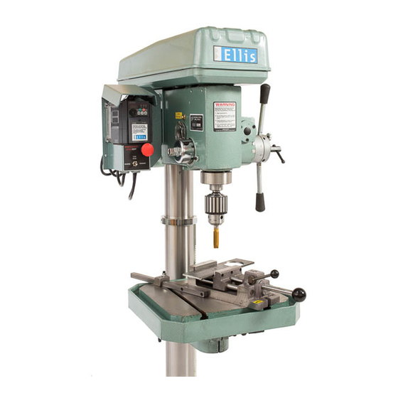
MODEL 9400 ELLIS VARIABLE SPEED DRILL PRESS WITH QUICK SPEED RANGE CHANGE Ellis Mfg. Company, Inc. • PO Box 930219 • Verona, WI 53593-0219 • 1-800-383-5547... -
Page 16: Operating Instructions
The complete speed variation from zero to the maximum of each range is made electronically using the speed control knob on the Ellis Variable Speed Control box. • High Speed, 0 to approximately 1200 RPM range. This is the range best suited for small drills.
Need help?
Do you have a question about the 9400 and is the answer not in the manual?
Questions and answers