Table of Contents
Advertisement
Quick Links
Advertisement
Table of Contents

Related Manuals for Ellis 9400

Summary of Contents for Ellis 9400
- Page 1 OWNER'S MANUAL 9400 VARIABLE SPEED DRILL PRESS SERIAL NUMBER: DATE PURCHASED:...
-
Page 2: Table Of Contents
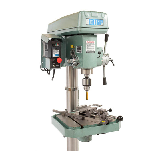
POWER FEED DRILL PRESS Infinitely Variable Speed Model 9400 Note: Ellis Manufacturing Co. Inc. reserves the right to make enhancements to the product at any time. Parts may change or improve, and the images displayed may not represent the actual product shipped. -
Page 3: Important Information
9400 Drill Press (2HP–110V or 220V). • For optimum performance, the Variable Speed This machine is suitable for: Control Box assembly is preset at the factory (Ellis). • Drilling, Reaming and Tapping: • Adjusting speed and torque (see page 8). -
Page 4: Safety
Use recommended speeds that are proper for the drill, workpiece 5059 Ellis Logo Label material and accessories used. 5051-1 (608) 845-6472 • EllisSaw.com 5061-2 Ellis MFG. CO., INC. • P.O. Box 930219 • Verona, WI 53593 5061 Forward/Reverse Label 5051 Warning Label EllisSaw.com... - Page 5 The circuit board is Dial not field repairable. Do not touch or adjust anything without calling Ellis Manufacturing Co. for instructions. The circuits in the VS Control Box are not isolated. Elements of the circuit board are Variable Speed at 230 Volts.
-
Page 6: Drill Specifications
DRILL SPECIFICATIONS Machine Specifications Drive Belt and Variable Speed Control Maximum Drill Diameter 1.062" Steel; 1.25" Cast Iron Tapping Capacity 3/4" – 10 NC T-Slots Two (2) 0.625" Slots on Worktable and Base Overall Size of Table 15.88" x 17.88" Table Machined Surface 15.88"... -
Page 7: Variable Speed Control Box
VARIABLE SPEED CONTROL BOX SET UP Stop The Red Emergency Stop Button stops the machine and automatically disconnects Important: Do not plug into the machine from electrical power after a time a GFCI circuit. delay of about twenty seconds. Use this as the Power Off switch at the end of the It is highly recommended to shift into High Torque work day. -
Page 8: Torque Range Operation Instructions
NOTE: The complete speed variation from zero to the Range Knob maximum of each range is made electronically using the 2 in 2 in speed control dial on the Ellis Variable Speed Control Box (+/- 10%). In In • High Speed, 0 to approximately 1265 RPM range. -
Page 9: Speed & Torque Range Overview
SPEED & TORQUE RANGE OVERVIEW SPINDLE SPEED The motor (#4647) drives the middle sheave (#8495) and the spindle pulley (#8434) by V-Belts. The spindle pulley drives the spindle and the taper sleeve. The spindle speed is variable by means of the Variable Speed Control Box and/or with Shift Handle. -
Page 10: Power Train Overview
POWER TRAIN OVERVIEW POWER FEED AND MANUAL FEED Manual Feed is accomplished by turning the Handle Hub (#8439) with either Feed Handle (#8474) located on the right side of Drill Press Head. Power Feed is accomplished by loosening Thumbscrew (#8383) on Handle Hub (#8439). To engage Power Feed, pull either Feed Handle (#8474) to the right, away from Head. -
Page 11: Power Train: Depth Of Drilled Hole
POWER TRAIN: DEPTH OF DRILLED HOLE "TO SET" DEPTH OF DRILLED HOLE OVERLOAD CLUTCH 1. Loosen Locking Handle (#8472) on Handle 1. The Drill Press is equipped with a power feed Hub (#8439). overload clutch. 2. The overload clutch protects the power train from 2. -
Page 12: Drill Chuck And Arbor
DRILL CHUCK AND ARBOR INSTALLING DRILL CHUCK AND ARBOR (FIGURE A) The Ellis 9400 Drill Press comes with a Morse Taper #3 (MT3). 1. Clean the inside taper in the drill press spindle. 2. Clean the outside of the tapers on the drills and chucks. - Page 13 Drill Chuck and Arbor Attachment Align slots Quill Slot 8073 Drift Key 8649 Chuck Figure A – Inserting Figure B – Removing Elevating, Rotating and Clamping the Table WARNING: Loosen column clamp screws before moving table otherwise damage will occur. 8407 Column Clamp Screw 8406 Elevating Handle 8486 Revolving Handle...
-
Page 14: Parts List
PARTS LIST HEAD ASSEMBLY (For Bearings See Page 17) Part Part Number Number Name Number Number Name 8437 Feed Pulley & Clutch ASSY 4943 V-Belt, Rear Drive 4938 V-Belt Upper, Power Feed 4647 Motor, 2HP (1.5KW) 8436 Nut (2) 8475 Motor Mounting Plate ASSY 8434 Spindle Pulley... - Page 15 HEAD ASSEMBLY PARTS EXPLOSION 40( not pictured) 1.800.383.5547...
- Page 16 PARTS LIST (CONT.) WORKTABLE AND BASE ASSEMBLY Column Assembly Parts Explosion (worm) (pin) (gear) Part Number Number Name 8401 Column Base 8403 Rack Gear 8404 Column 8486 Revolving Handle 8406 Elevating Handle 8407 Column Clamp Screw 8077 Column Ring 8410 Worktable 8442 Table Bracket...
- Page 17 8437 Feed Pulley with 8495 Middle Overload Clutch ASSY 8434 Spindle Pulley Sheave ASSY Spindle The chart below identifies the bearings in the various locations. The Ellis Part Number is required for replacement orders. Part Number Number Bearing Type Location...
-
Page 18: Maintenance
MAINTENANCE LUBRICATION STANDARD MAINTENANCE The Power Feed Unit Box has two (2) grease fittings. • Keep table and sliding parts clean of dirt and chips. It is important that the operator grease the machine • Every three months lower the quill, wipe clean and frequently. -
Page 19: Troubleshooting
TROUBLESHOOTING Problem Probable Cause Remedy Power cord not plugged into source Plug into receptacle VS Control Box not "ON" Push and turn Emergency Stop Button Speed Dial in "0" position Turn dial counterclockwise for more speed Motor is too hot—heat switch tripped Wait for motor to cool off Power cord plugged into GFCI Plug into an unprotected outlet, preferably... -
Page 20: Accessories
8650 (通)用件登记 描 图 描 校 The 9400 is a drill press designed for drilling The JT4 drill chuck is designed for heavy-duty drilling 旧底图总号 图号 底图总号 and tapping. It can provide support for those applications. The chuck and arbor is ground with high TC18-2 图... - Page 21 借(通)用件登记 描 图 UNLESS OTHERWISE SPECIFIED: NAME DATE 描 校 This Ellis Vise will hold and move. It can move in and The Chuck Guard protects from accidental contact with DRAWN DIMENSIONS ARE IN INCHES TOLERANCES: TITLE: CHECKED FRACTIONAL 旧底图总号...
-
Page 22: Maintenance Log
MAINTENANCE LOG Date Maintenance/Service Performed Initials Reminder: Use Lithium Grease. Do not mix synthetic and mineral based grease. EllisSaw.com... -
Page 23: Overview Of Terms
OVERVIEW OF TERMS Cover (Belts and Pulleys Cover) Head Stock Torque Bolt Range ASSY Power Feed Unit Motor Shift Handle Quill Morse Taper Bore Feed Handles Rack Gear Worktable Column Clamp Screw Table Clamp Screw Table Bracket Column Clamp Screw Column ASSY Column Base 1.800.383.5547... - Page 24 CHECK OUT OUR OTHER PRODUCTS Band Saws Band Saw Blades Belt Grinder www.EllisSaw.com Ellis Mfg. Company, Inc. • PO Box 930219 • Verona, WI 53593-0219 1-800-383-5547 • 608-845-6472 • Fax 608-845-5199 ©2021...
Need help?
Do you have a question about the 9400 and is the answer not in the manual?
Questions and answers
My model 9400 drill press throws a red light fault when I turn the main switch on and I can’t get it to turn on what could be the problem
A red light fault on an Ellis 9400 drill press when turning on the main switch could be caused by a low supply voltage or use of an inappropriate power source, such as an extension cord, adapter, surge protector, or GFCI-protected receptacle. The machine requires a dedicated 20 amp, 115-Volt AC circuit for proper operation. Loose wire connections at the terminals may also contribute.
This answer is automatically generated