Table of Contents
Advertisement
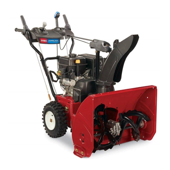
Power Max 826 O/OE Snowthrower
Model No. 38597-Serial No. 313000001 and Up
Model No. 38629-Serial No. 313000001 and Up
Introduction
This machine is intended to be used by residential
homeowners or professional, hired operators. It is
designed primarily for removing snow from paved
surfaces, such as driveways and sidewalks, and other
surfaces for traffic on residential or commercial
properties. It is not designed for removing materials
other than snow.
Read this information carefully to learn how to operate and
maintain your machine properly and to avoid injury and
machine damage. You are responsible for operating the
machine properly and safely.
You may contact Toro directly at www.Toro.com for machine
and accessory information, help finding a dealer, or to register
your machine.
Whenever you need service, genuine Toro parts, or additional
information, contact an Authorized Service Dealer or Toro
Customer Service and have the model and serial numbers of
your machine ready. Figure 1 identifies the location of the
model and serial numbers on the machine. Write the numbers
in the space provided.
1. Model and serial number location
Model No.
Serial No.
This manual identifies potential hazards and has safety
messages identified by the safety alert symbol (Figure 2),
© 2012-The Toro® Company
8111 Lyndale Avenue South
Bloomington, MN 55420
Figure 1
Register at www.Toro.com.
which signals a hazard that may cause serious injury or death
if you do not follow the recommended precautions.
1. Safety alert symbol
This manual uses 2 words to highlight information.
Important calls attention to special mechanical information
and Note emphasizes general information worthy of special
attention.
Replacement Engine Owner's Manuals may be ordered
through the engine manufacturer.
Contents
Introduction .................................................................. 1
Training ................................................................. 3
Preparation............................................................. 3
Operation............................................................... 3
Maintenance and Storage.......................................... 4
Toro Snowthrower Safety ......................................... 4
Sound Pressure ....................................................... 4
Sound Power .......................................................... 4
Vibration................................................................ 4
Safety and Instructional Decals ................................. 4
Setup ............................................................................ 7
1 Installing the Upper Handle.................................... 7
2 Installing the Traction Control Linkage .................... 8
3 Installing the Chute Control Rod ............................. 9
4 Filling the Engine with Oil.....................................10
5 Checking the Tire Pressure ....................................10
6 Checking the Skids ...............................................10
7 Checking the Traction Drive Operation ...................10
Product Overview .........................................................12
Operation ....................................................................12
Freewheeling or Using the Self-propel Drive...............12
Filling the Fuel Tank ...............................................13
Starting the Engine .................................................14
Stopping the Engine ...............................................15
Operating the Traction Drive ...................................16
Operating the Speed Selector ...................................16
Operating the Auger/Impeller Drive.........................16
Original Instructions (EN)
All Rights Reserved *3373-710* A
Printed in the USA
Form No. 3373-710 Rev A
Operator's Manual
Figure 2
®
......................................17
Advertisement
Table of Contents

Related Manuals for Toro PowerMax 826 O


Summary of Contents for Toro PowerMax 826 O
-
Page 1: Table Of Contents
Note emphasizes general information worthy of special machine properly and safely. attention. You may contact Toro directly at www.Toro.com for machine Replacement Engine Owner’s Manuals may be ordered and accessory information, help finding a dealer, or to register through the engine manufacturer. - Page 2 Unclogging the Discharge Chute ......17 Preventing Freeze-up ..........17 Operating Tips ............18 Maintenance ..............18 Recommended Maintenance Schedule(s) ......18 Preparing for Maintenance........20 Checking the Engine Oil Level .........20 Checking and Adjusting the Skids and Scraper ..............20 Checking and Adjusting the Traction Cable ....20 Checking the Auger Gearbox Oil Level ......21 Changing the Engine Oil .........21 Adjusting the Discharge Chute Latch ......22...
-
Page 3: Training
Safety safety glasses or eye shields during operation or while performing an adjustment or repair. This machine meets or exceeds the ISO standard 8437 in effect at the time of production. Operation Read and understand the contents of this manual before •... -
Page 4: Maintenance And Storage
Uncertainty Value (K) of 2 dBA. The sound power level was determined according to the Toro Snowthrower Safety procedures outlined in EN ISO 3744. The following list contains safety information specific to Toro Vibration products or other safety information that you must know. •... - Page 5 107-3040 1. Cutting dismemberment, impeller and cutting dismemberment, auger hazards—keep bystanders a safe distance from the machine. 106-4525 Reorder part no. 112-6633 1. Fast 3. Slow 2. Forward speeds 4. Reverse speeds 112-6625 Reorder part no. 112-6629 1. Cutting/dismemberment hazard, impeller—do not place your hand in the chute;...
- Page 6 Briggs & Stratton Part No. 273676 3. Fast 1. Stop 2. Slow Briggs & Stratton Part No. 277588 1. Primer 3. Ignition key out Briggs & Stratton Part No. 275949 (Engine—Stop) 1. Choke on (Choke) 2. Choke off (Run) 2. Ignition key in (Engine—Run) Briggs &...
-
Page 7: Setup
Setup Loose Parts Use the chart below to verify that all parts have been shipped. Procedure Description Qty. Handle bolts Curved washers Install the upper handle. Locknuts – No parts required Install the traction control linkage. Carriage bolts Install the chute control rod. Locknuts –... -
Page 8: Installing The Traction Control Linkage
Figure 6 1. Speed selector lever 3. Inner washer 2. Trunnion 4. Outer washer Figure 4 Note: To make installation easier, leave the flat washer on the trunnion (Figure 6). 4. Shift the speed selector lever into Position R2. 5. Rotate the lower link arm fully upward (counterclockwise) (Figure 7). -
Page 9: Installing The Chute Control Rod
Note: For easier installation, look down through the opening in the speed selector (Figure 8). Figure 9 Figure 8 1. Short rod 2. Long chute control rod 1. Speed selector 4. Insert the front end of the rod into the opening in the back of the chute gear cover until it slides into the chute gear (Figure 10). -
Page 10: Filling The Engine With Oil
7. Hold the blue trigger cap down and rotate the Quick Stick in a circle to ensure that the chute and deflector operate smoothly. Filling the Engine with Oil No Parts Required Procedure Your machine comes with oil in the engine crankcase. Figure 13 Note: Before starting the engine, check the oil level and add oil if necessary. -
Page 11: Checking The Traction Drive Operation
6. Squeeze the left hand (traction) lever to the hand-grip (Figure 14). The machine should move forward. If the machine does not move or moves rearward, complete the Checking the Traction Drive following: Operation A. Release the traction lever and stop the engine. B. -
Page 12: Product Overview
Product Overview Figure 17 1. Snow cleanout tool (attached to the handle) Operation Note: Determine the left and right sides of the machine from the normal operating position. Freewheeling or Using the Self-propel Drive To disengage the self-propel drive (freewheel) when storing the snowthrower, slide the wheels inward and insert the axle g018609 pins through the outer axle holes, but not through the wheel... -
Page 13: Filling The Fuel Tank
Filling the Fuel Tank DANGER Gasoline is extremely flammable and explosive. A fire or explosion from gasoline can burn you and others. • To prevent a static charge from igniting the gasoline, place the container and/or machine on the ground before filling, not in a vehicle or on an object. -
Page 14: Starting The Engine
Starting the Engine 1. Check the engine oil level. Refer to Checking the Engine Oil Level in Maintenance. 2. Turn the fuel shutoff valve 1/4 turn counterclockwise to open it (Figure 21). Figure 21 3. Insert the ignition key (Figure 22). Figure 23 5. -
Page 15: Stopping The Engine
Stopping the Engine 1. Move the throttle to the Slow position, and then to the Stop position (Figure 27). Figure 26 1. Electric-starter button 3. Recoil starter (only 38629) Figure 27 2. Electric starter plug (only 38629) 2. Wait for all moving parts to stop before leaving the Note: To use the electric starter, connect a power cord operating position. -
Page 16: Operating The Traction Drive
Operating the Traction Drive Operating the Speed Selector The speed selector has 6 forward and 2 reverse gears. To CAUTION change speeds, release the traction lever and shift the speed selector lever to the desired position (Figure 30). The lever If the traction drive is not properly adjusted, the locks in a notch at each speed selection. -
Page 17: Operating The Quick Stick
• If the chute does not turn as far to the left as it does to WARNING the right, ensure that the cable is routed to the inside of If the auger and impeller continue to rotate the handles. Refer to Installing the Upper Handle. when you release the auger/impeller lever, you •... -
Page 18: Operating Tips
operating any control or part, start the engine and let it WARNING run for a few minutes. The rotor blades can throw stones, toys, and other • After using the machine, let the engine run for a few foreign objects and cause serious personal injury to minutes to prevent moving parts from freezing. - Page 19 • Have an Authorized Service Dealer inspect and replace the traction drive belt and/or the auger/impeller drive belt, if necessary. Important: You can find more information about maintaining and servicing your machine at www.Toro.com. Important: Refer to your engine operator's manual for additional maintenance procedures. For engine adjustments,...
-
Page 20: Preparing For Maintenance
Preparing for Maintenance 1. Move the machine to a level surface. 2. Stop the engine and wait for all moving parts to stop. 3. Disconnect the spark plug wire. Refer to Replacing the Spark Plug. Figure 36 Checking the Engine Oil Level 1. -
Page 21: Checking The Auger Gearbox Oil Level
Figure 37 Figure 39 1. Pin 3. Remove the pipe plug from the gearbox. If the left hand (traction) cable is not properly adjusted, do 4. Check the oil level in the gearbox. The oil should be at the following steps: the point of overflowing at the filler opening. -
Page 22: Adjusting The Discharge Chute Latch
1. Remove the fastener on the gear cover (Figure 42), lift the front of the cover up, and slide it back and out of the way. Figure 42 Figure 40 2. Loosen the bolt on the cable clamp (Figure 43). 1. -
Page 23: Replacing The Drive Belts
If the auger/impeller drive belt or the traction drive belt becomes worn, oil-soaked, or otherwise damaged, go to WARNING www.Toro.com for additional service information or have an Authorized Service Dealer replace the belt. • Gasoline vapors can explode. • Do not store gasoline more than 30 days. -
Page 24: Removing The Machine From Storage
Removing the Machine from Storage 1. Remove the spark plug and spin the engine rapidly using the starter to blow the excess oil from the cylinder. 2. Install the spark plug by hand and then torque it to 15 ft-lb (20.4 N-m). 3. -
Page 25: Troubleshooting
Troubleshooting Problem Possible Cause Corrective Action Electric starter does not turn (electric-start 1. The power cord is disconnected at the 1. Connect the power cord to the outlet models only) outlet or the machine. and/or the machine. 2. The power cord is worn, corroded, or 2. - Page 26 5. Unclog the discharge chute. 6. The auger/impeller drive belt is loose 6. Install and/or adjust the auger/impeller or is off the pulley. drive belt; refer to www.Toro.com for servicing information or take the machine to an Authorized Service Dealer.
- Page 27 Spypros Stavrinides Limited Cyprus 357 22 434131 Surge Systems India Limited India 91 1 292299901 T-Markt Logistics Ltd. Hungary 36 26 525 500 Toro Australia Australia 61 3 9580 7355 Toro Europe NV Belgium 32 14 562 960 374-0269 Rev C...
-
Page 28: Lyndale Avenue South Bloomington, Mn
Toro's option, under warranty at no cost for parts and labor. Frame failure due to misuse or abuse and failure or repair required due to rust or corrosion are not covered.