Pioneer XV-DV333 Service Manual
Dvd /cd receiver
Hide thumbs
Also See for XV-DV333:
- Operating instructions manual (98 pages) ,
- Service manual (108 pages) ,
- Operating instructions manual (102 pages)
Table of Contents
Advertisement
DVD/CD RECEIVER
XV-DV333
XV-DV434
XV-DV535
THIS MANUAL IS APPLICABLE TO THE FOLLOWING MODEL(S) AND TYPE(S).
Model
Type
XV-DV333
MLXJ
XV-DV333
YLXJ/NC
XV-DV333
YPWXJ
XV-DV434
MLXJ
XV-DV434
YLXJ/NC
XV-DV434
YPWXJ
XV-DV535
MLXJ
XV-DV535
YLXJ/NC
For details, refer to "Important Check Points for Good Servicing".
PIONEER CORPORATION
PIONEER ELECTRONICS (USA) INC. P.O. Box 1760, Long Beach, CA 90801-1760, U.S.A.
PIONEER EUROPE NV Haven 1087, Keetberglaan 1, 9120 Melsele, Belgium
PIONEER ELECTRONICS ASIACENTRE PTE. LTD. 253 Alexandra Road, #04-01, Singapore 159936
PIONEER CORPORATION 2005
Power Requirement
AC220-230V
AC240V
AC240V
AC220-230V
AC240V
AC240V
AC220-230V
AC240V
4-1, Meguro 1-chome, Meguro-ku, Tokyo 153-8654, Japan
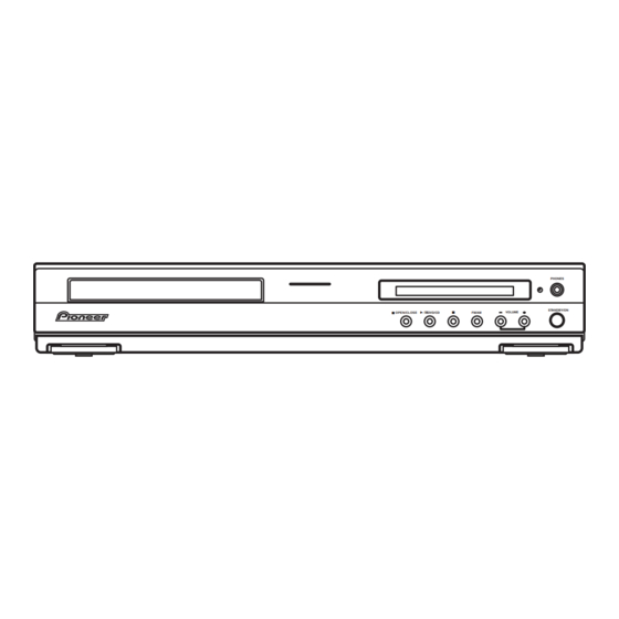
PHONES
STANDBY/ON
OPEN/CLOSE
DVD/CD
FM/AM
VOLUME
XV-DV333
Regional restriction
codes (Region No.)
3
3
4
3
3
4
3
3
T-ZZK JULY 2005 printed in Japan
ORDER NO.
RRV3171
Remarks
Advertisement
Table of Contents
Troubleshooting

Related Manuals for Pioneer XV-DV333


Summary of Contents for Pioneer XV-DV333
- Page 1 PIONEER CORPORATION 4-1, Meguro 1-chome, Meguro-ku, Tokyo 153-8654, Japan PIONEER ELECTRONICS (USA) INC. P.O. Box 1760, Long Beach, CA 90801-1760, U.S.A. PIONEER EUROPE NV Haven 1087, Keetberglaan 1, 9120 Melsele, Belgium PIONEER ELECTRONICS ASIACENTRE PTE. LTD. 253 Alexandra Road, #04-01, Singapore 159936...
-
Page 2: Safety Information
The interlock mechanism mentioned above becomes invalid in this mode. 2. When the cover is open, close viewing through the objective lens with the naked eye will cause exposure to the laser beam. ∗ : Refer to page 67. XV-DV333... - Page 3 To protect products from damages or failures during transit, the shipping mode should be set or the shipping screws should be installed before shipment. Please be sure to follow this method especially if it is specified in this manual. XV-DV333...
-
Page 4: Table Of Contents
7.1.9 ID NUMBER AND ID DATA SETTING ....................78 7.1.10 DSP TROUBLE SHOOTING ......................81 7.1.11 DISASSEMBLY..........................83 7.2 PARTS..............................92 7.2.1 IC ............................... 92 7.3 EXPLANATION ............................96 7.3.1 SEQUENCE AFTER POWER ON..................... 96 7.3.2 PROTECTION CIRCUIT........................97 8. PANEL FACILITIES ............................102 XV-DV333... -
Page 5: Specifications
Digital Theater Systems, Inc. Accessories • Power cord • FM Antenna (ADH7030) • Video Cable • Remote Control (MLXJ, YLXJ/NC : ADG1154) (L = 1.5m) (XDE3046) (XV-DV333 : XXD3093) (YPWXJ : ADG7099) (XV-DV434 : XXD3093) (XV-DV535 : XXD3095) STANDBY/ON FM/AM L1/L2 TUNER... -
Page 6: Exploded Views And Parts List
Screws adjacent to mark on product are used for disassembly. For the applying amount of lubricants or glue, follow the instructions in this manual. (In the case of no amount instructions, apply as you think it appropriate.) 2.1 PACKING Front side XV-DV333... - Page 7 • • • • • • • • • • • • Remote Control See Contrast table(2) (2) CONTRAST TABLE XV-DV333/MLXJ, YLXJ/NC, YPWXJ, XV-DV434/MLXJ, YLXJ/NC, YPWXJ, XV-DV535/MLXJ and YLXJ/NC are constructed the same except for the following: XV-DV333 XV-DV333 XV-DV333...
-
Page 8: Exterior Section
2.2 EXTERIOR SECTION Except YPWXJ MLXJ only Refer to "2.4 05 LOADER ASSY." 46 47 Cleaning paper GED-008 YPWXJ only Refer to "2.3 FRONT PANEL SECTION." XV-DV333... - Page 9 See Contrast table(2) NSP 28 05 LOADER Assy VWT1219 Adaptor 05L ANW7282 Adaptor 05R ANW7283 (2) CONTRAST TABLE XV-DV333/MLXJ, YLXJ/NC, YPWXJ, XV-DV434/MLXJ, YLXJ/NC, YPWXJ, XV-DV535/MLXJ and YLXJ/NC are constructed the same except for the following: XV-DV333 XV-DV333 XV-DV333 XV-DV434 XV-DV434 XV-DV434 XV-DV535 XV-DV535 Mark No.
-
Page 10: Front Panel Section
VAM1129 Illumination Lens AAK8214 Display Window See Contrast table(2) AEB7090 FUNC. Button XAD3209 (2) CONTRAST TABLE XV-DV333/MLXJ, YLXJ/NC, YPWXJ, XV-DV434/MLXJ, YLXJ/NC, YPWXJ, XV-DV535/MLXJ and YLXJ/NC are constructed the same except for the following: XV-DV333 XV-DV333 XV-DV333 XV-DV434 XV-DV434 XV-DV434 XV-DV535 XV-DV535 Mark No. -
Page 11: Loader Assy
JGZ17P028FTC Flexible Cable (24P) VDA2008 Screw VBA1094 Connector Assy 2P VKP2253 Tray VNL1920 Floating Rubber VEB1351 Clamp Magnet VMG1029 Belt VEB1358 Stabilizer VNE2253 Loading Base VNL1917 Float Base 04 VNL1968 Drive Cam VNL1919 Gear Pulley VNL1921 Loading Gear VNL1922 XV-DV333... - Page 12 Rear View Daifree Daifree No. 23 No. 23 GEM1036 GEM1036 Tray Tray Concave of unevenness Concave of unevenness Inner side of a ditch Daifree GEM1036 Top View Bottom View Side of the rib Concave of unevenness Daifree Daifree GEM1036 GEM1036 XV-DV333...
-
Page 13: Traverse Mechanism Assy-S
Skew Screw VK1 DBA1211 Guide Shaft VK1 DLA1940 Sub Guide Shaft VK1 DLA1941 Skew Spring VK1 DBH1516 NSP 5 Joint VK1B DNK4272 NSP 12 Stepping Screw DBA1205 Spindle Screw VK1(for Service) DBA1252 Joint Spring VK1 DBK1235 Stepping Motor VK1 DXM1201 XV-DV333... -
Page 14: Block Diagram And Schematic Diagram
• Dolby Digital Decoder UNIT • Dolby PrologicII • DTS Decoder DSP ASSY ATTENUATOR IC701 LINE 1 IC3001 - 6dB - 10dB AK4628VQE INPUT BUFFER IC3003 SELECTOR TV IN CODEC CN5102 VDET VPR+8 VPR+8M VDVD+12 LIVE AC IN NEUTRAL CN3101 XV-DV333... -
Page 15: Video Assy
Centre CENTRE • 6ch E-vol IC3401 STK433-270 +0dB SL/SR SL/SR • 3ch Power Amp WIRE LESS MODEL ONLY REC OUT WIRELESS OUT IC3002 AMP UNIT 6CH SELECT WIRELESS TRADE1 ASSY +6dB TRADE2 IC9091 ASSY (1/2) POWER SUPPLY ASSY (1/2) XV-DV333... -
Page 16: Overall Wiring Connection Diagram
Therefore, when replacing, be sure to use parts of identical designation. ÷ : The power supply is shown with the marked box. XKP3084 MLXJ : XTS3077 YLXJ/NC, YPWXJ : XTS3078 YGND YGND VIDEO ASSY CbGND (XWZ3980) POWER ASSY(XWZ3975) 1/2- DVDM ASSY (AWM7964) DVD ASSY (AXA7145) LOAB ASSY (VWG2346) XV-DV333... - Page 17 TRADE 2 ASSY (XWZ3998) CN5701 52045-1145 FM/AM TUNER UNIT (AXX7173) JA8602 TORX179PL * No schematic diagram 11pinFFC 1/4- LED ASSY JA3001 CONTROL ASSY (XWZ3969 : XV-DV333) (XWZ4000) AKP7050 (XWZ3984 : XV-DV434) (XWZ3989 : XV-DV535) CN5611 52045-1545 CN5601 52044-1545 HPDET VFDP XFLRST FLCS...
-
Page 18: Dvdm Assy (1/2)
: TRACKING SERVO LOOP LINE : STEPPING SERVO LOOP LINE (C/V) : VIDEO SIGNAL ROUTE (R/Cr) : VIDEO SIGNAL ROUTE(R/Cr) (G/Y) : VIDEO SIGNAL ROUTE(G/Y) (B/Cb) : VIDEO SIGNAL ROUTE(B/Cb) (S_Y) : S VIDEO SIGNAL ROUTE (S_C) : S VIDEO SIGNAL ROUTE XV-DV333... - Page 19 DVDM ASSY (AWM7964) XV-DV333...
-
Page 20: Dvdm Assy (2/2)
3.4 DVDM ASSY (2/2) DVDM ASSY (AWM7964) XV-DV333... - Page 21 : VIDEO SIGNAL ROUTE : VIDEO SIGNAL ROUTE(G) (R/Cr) : VIDEO SIGNAL ROUTE(R/Cr) : VIDEO SIGNAL ROUTE(B) (G/Y) : VIDEO SIGNAL ROUTE(G/Y) (B/Cb) : VIDEO SIGNAL ROUTE(B/Cb) (S_Y) : S VIDEO SIGNAL ROUTE (S_C) : S VIDEO SIGNAL ROUTE XV-DV333...
-
Page 22: Dsp Assy
3.5 DSP ASSY DSP ASSY (AWX8587) CN951 CN5620 XV-DV333... - Page 23 : AUDIO SIGNAL ROUTE(Surround L ch) : AUDIO SIGNAL ROUTE(DIGITAL) : AUDIO SIGNAL ROUTE(Center ch) (SW) (AD) : AUDIO SIGNAL ROUTE(Sub Woofer ch) : AUDIO DATA SIGNAL ROUTE (FL) (AD) (AD) (AD) (SL) (AD) (sw) (DVD) (DVD) CN901 CN5613 XV-DV333...
-
Page 24: 6Ch Amp Assy
3.6 6CH AMP ASSY (SL) (SW) (FL) CN3001 CN3002 XV-DV333... - Page 25 : Refer to "7.3.2 PROTECTION CIRCUIT. (SL) (SW) (FL) (FL) : AUDIO SIGNAL ROUTE (Front L ch) (SL) : AUDIO SIGNAL ROUTE (Surround L ch) : AUDIO SIGNAL ROUTE (Center ch) (SW) : AUDIO SIGNAL ROUTE (Sub Woofer ch) XV-DV333...
-
Page 26: Control (1/4) And Trade 2 Assys
3.7 CONTROL (1/4) and TRADE 2 ASSYS CONTROL ASSY (XWZ3969 : XV-DV333)(XWZ3984 : XV-DV434) (XWZ3989 : XV-DV535) 2/4-4/4 2/4-4/4 XV-DV535 XV-DV333 XV-DV333 XV-DV434 XV-DV535 CN5613 CN5612 (DVD) CN5620 (DVD) (DVD) DSPAOUT XV-DV333... - Page 27 : AUDIO SIGNAL ROUTE (Surround L ch) 3/4,4/4 U-COM (DVD) : AUDIO SIGNAL ROUTE (DVD L ch) : AUDIO SIGNAL ROUTE (Center ch) (SW) : AUDIO SIGNAL ROUTE (DIGITAL) : AUDIO SIGNAL ROUTE (Sub Woofer ch) 3/4,4/4 (FL) : AUDIO SIGNAL ROUTE (Front L ch) XV-DV333...
-
Page 28: Control (2/4) Assy
: AUDIO SIGNAL ROUTE (SW) (FL) : SWch AUDIO SIGNAL ROUTE : FLch AUDIO SIGNAL ROUTE (SW) : SWch AUDIO SIGNAL ROUTE(THEATER BASS) (FL) (FL) (FL) (FL) (FL) LPF & GAIN E-VOL (SL) (SL) (SW) (SL) (FL) DSPAOUT (SW) (SW) 1/4,2/4-4/4 XV-DV333... - Page 29 CONTROL ASSY (XWZ3969 : XV-DV333) (XWZ3984 : XV-DV434) (XWZ3989 : XV-DV535) ANDREW CIRCUIT (FL) (SL) (SW) (SR) (SL) (FR) (FL) (SW) (SW) (SW) XV-DV333...
-
Page 30: Control (3/4) Assy
3.9 CONTROL (3/4) ASSY (PRETVL) (TVL) (TXL) (LINE1L) (FL) (WIRELESS_L) XV-DV535 XV-DV333... - Page 31 2/4, 4/4 CN5701 (TXL) (TXL) : AUDIO SIGNAL ROUTE (FL) : FLch AUDIO SIGNAL ROUTE CONTROL ASSY (XWZ3969 : XV-DV333) (TVL) : TVIN Lch AUDIO SIGNAL ROUTE (XWZ3984 : XV-DV434) : DIGITAL AUDIO SIGNAL ROUTE (XWZ3989 : XV-DV535) (TXL) : TX Lch AUDIO SIGNAL ROUTE...
-
Page 32: Control (4/4) Assy
3.10 CONTROL (4/4) ASSY CONTROL ASSY (XWZ3969 : XV-DV333) (XWZ3984 : XV-DV434) 2/4, 3/4 (XWZ3989 : XV-DV535) (FL) (FL) (FL) (FR) (FR) (FR) 1/4,3/4 1/4-3/4 XV-DV333... - Page 33 1/4- 3/4 (FL) : FLch AUDIO SIGNAL ROUTE : DIGITAL AUDIO SIGNAL ROUTE 1/4-3/4 XV-DV333...
-
Page 34: Power Assy
3.11 POWER ASSY REK1026 (T2.5A) XTS3074 REK1029 (T5.0A) (FL) (SW) (SL) CN5521 CN5522 to TRADE2 ASSY CN5521 to TRADE2 ASSY CN5522 XV-DV333... - Page 35 : AUDIO SIGNAL ROUTE(Sub Woofer ch) (SL) CN901 : AUDIO SIGNAL ROUTE(Surround L ch) from dvdm ASSY • NOTE FOR FUSE REPLACEMENT CAUTION - FOR CONTINUED PROTECTION AGAINST RISK OF FIRE. REPLACE WITH SAME TYPE AND RATINGS OF FUSE. XV-DV333...
-
Page 36: Trade 1 And Video Assys
3.12 TRADE 1 and VIDEO ASSYS TRADE 1 ASSY (XWZ3997) CAUTION : FOR CONTINUED PROTECTION AGAINST RISK OF FIRE. REPLACE ONLY WITH SAME TYPE NO. 491007 MFD, BY LITTELFUSE INK. FOR IC25 (AEK7047). (C/V) (CY/G) (PB/B) (PR/R) XV-DV333... - Page 37 : VIDEO SIGNAL ROUTE (PR/R) VIDEO ASSY (XWZ3980) (CY/G) : S VIDEO SIGNAL ROUTE (Y) : VIDEO SIGNAL ROUTE (CY/G) (PB/B) : VIDEO SIGNAL ROUTE (PB/B) : S VIDEO SIGNAL ROUTE (Y) (CY/G) (PB/B) (PB/B) (PR/R) (PR/R) (C/V) (C/V) XV-DV333...
-
Page 38: Display And Led Assys
3.13 DISPLAY and LED ASSYS DISPLAY ASSY (XWZ3979) XV-DV333... - Page 39 FL Spacer XEB3046 LED ASSY (XWZ4000) Switches DISPLAY ASSY S5921 : STANDBY/ON S5922 : UP + VOLUME S5923 : – DOWN S5924 : FM/AM S5925 : 7 (STOP) S5926 : 6 DVD/CD (PLAY/PAUSE) S5927 : 0 OPEN/CLOSE XV-DV333...
-
Page 40: Waveforms
IC201-pin225 [ASPDIF AUDIO DIGITAL SIGNAL] [SPINDLE (WVU)] V: 2V/div. H: 500nsec/div. V: 2V/div. H: 2msec/div. IC401-pin23 [CompositeVideo Out] IC401-pin21 [S VIDEO OUT - Y] V: 1V/div. H: 10µsec/div. V: 1V/div. H: 10µsec/div. IC401-pin26 [S VIDEO OUT - C] V: 1V/div. H: 10µsec/div. XV-DV333... -
Page 41: Pcb Connection Diagram
Resistor array 3-terminal regulator 4.1 LOAB ASSY SIDE A SIDE B LOAB ASSY LOAB ASSY VNP1836-C LOAB PNE-1B1 S101 LOAD+ VWG2279- CN602 CN602 C102 LOAD- VWG2346- C101 CN601 (VNP1836-C) (VNP1836-C) CN601 CN602 CN601 CN601 CN602 CN103 LOADING MOTOR ASSY XV-DV333... -
Page 42: Dvdm Assy
Q304 IC761 Q305 Q562 IC751 Q564 IC101 IC731 Q565 Q561 Q881 Q308 Q533 Q534 Q731 Q801 Q307 IC531 Q535 Q532 Q531 IC711 Q506 Q503 Q504 IC591 IC501 IC204 Q502 Q501 Q401 Q505 IC201 Q851 Q821 Q481 (ANP7527-A) CN104 CN601 XV-DV333... - Page 43 SIDE B SIDE B DVDM ASSY Q732 Q201 IC203 IC451 IC202 IC401 (ANP7527-A) XV-DV333...
-
Page 44: Dsp, Trade 2 And Trade 1 Assys
4.3 DSP, TRADE 2 and TRADE 1 ASSYS SIDE A SIDE A DSP ASSY IC801 IC871 IC701 IC601 IC901 (ANP7526-A) IC802 CN951 CN701 CN901 (ANP7526-A) CN5620 CN5612 CN5613 TRADE 2 ASSY TRADE 1 ASSY (XNP3087-B) (XNP3087-B) XV-DV333... - Page 45 SIDE B SIDE B DSP ASSY IC951 IC851 Q801 (ANP7526-A) CN901 CN701 CN951 TRADE 2 ASSY TRADE 1 ASSY (XNP3087-B) (XNP3087-B) XV-DV333...
-
Page 46: 6Ch Amp Assy
4.4 6CH AMP ASSY SIDE A SIDE A 6CH AMP (XNP3088-C) XV-DV333... - Page 47 SIDE B SIDEB 6CH AMP D3301 R3591 D3581 (XNP3088-C) XV-DV333...
-
Page 48: Control Assy
4.5 CONTROL ASSY SIDE A To FM/AM TUN CONTROL ASSY UNIT CN5701 CN901 CN701 CN5511 XV-DV333... - Page 49 SIDE A FM/AM TUNER CN951 CN5601 CN5522 (XNP3085-C) XV-DV333...
- Page 50 SIDE B CN5502 CN5501 XV-DV333...
- Page 51 SIDE B CONTROL ASSY CN5701 (XNP3085-C) XV-DV333...
-
Page 52: Display, Video And Led Assys
4.6 DISPLAY, VIDEO and LED ASSYS SIDE A SIDE A DISPLAY ASSY VIDEO ASSY (XNP3086-B) CN8801 CN902 CN5611 LED ASSY H I K (XNP3086-B) (XNP3086-B) XV-DV333... - Page 53 SIDE B SIDE B DISPLAY ASSY VIDEO ASSY Q3921 Q3901 Q5691 IC5601 (XNP3086-B) CN8801 LED ASSY Q5693 Q5692 (XNP3086-B) (XNP3086-B) XV-DV333...
-
Page 54: Power Assy
4.7 POWER ASSY SIDE A SIDE A POWER ASSY (XNP3086-B) XV-DV333... - Page 55 SIDE B SIDE B POWER ASSY (XNP3086-B) XV-DV333...
-
Page 56: Pcb Parts List
Ex.2 When there are 3 effective digits (such as in high precision metal film resistors). 5.62k Ω 562 x 10 5621 RN1/4PC 5 6 2 1 7 7 7 7 LIST OF HOLE PCB ASSEMBLIES XV-DV333 XV-DV434 XV-DV535 Mark Symbol and Description /MLXJ, YLXJ/NC, YPWXJ /MLXJ, YLXJ/NC, YPWXJ /MLXJ, YLXJ/NC 1..LOAB ASSY... - Page 57 9091 Pin Jack 2P Not used Not used AKB1233 • FM/AM TUNER UNIT This assembly has no service parts. 7 7 7 7 PCB PARTS LIST FOR XV-DV333/MLXJ UNLESS OTHER WISE NOTED Mark No. Description Part No. Mark No. Description Part No.
- Page 58 C816, C821, C828, C832, C851 CCSRCH471J50 > MTZJ15(B) C913, C916, C951 CCSRCH471J50 D3393, D3394 MTZJ18(B) C819, C820 CCSRCH5R0C50 > MTZJ18(B) C615, C703, C715, C834, C835 CEVW101M16 D3385, D3386 MTZJ36(B) C902, C903 CEVW101M16 > MTZJ7R5(B) C718 CEVW2R2M50 UDZS18B C614 CKSRYB102K50 XV-DV333...
- Page 59 C3919, C3920 CEANP470M16 C3029, C3030, C3035-C3038 CEAT100M50 OTHERS C3917, C3918, C3946, C3953, C5711 CEAT100M50 CN5511, CN5512, CN5521, CN5522 XKP3082 C8305, C8306 CEAT100M50 23P SOCKET C5572 CEAT101M10 CEAT101M16 C3113, C3114 CEAT221M10 CONTROL ASSY C3134 CEJQ100M16 SEMICONDUCTORS C3086, C3093, C5576 CEJQ100M50 XV-DV333...
- Page 60 JA8851 4P PIN JACK VKB1168 DISPLAY ASSY CN8801 27P FFC CONNECTOR VKN1258 SEMICONDUCTORS IC5601 PT6302LQ-003 Q5691, Q5692 2SC4081 POWER ASSY Q5693 DTC143EUA SEMICONDUCTORS Q3901, Q3921 XP4506 > D5662 MTZJ36(B) IC51 NJM78M56FA > 2SB1565 D5561 MTZJ5R6(B) Q3601, Q3602, Q3611, Q3612 2SC4081 XV-DV333...
- Page 61 C23, C24 (5600uF/35V) XCH3023 C15, C16 (2200uF/63V) XCH3024 RESISTORS R3607, R3608, R3617, R3618 ACN7112 R3627, R3628 (0.1/ 2W) ACN7112 R3361, R3362, R3461, R3462, R3561 RD1/2PMF101J R3661 RD1/2PMF101J RD1/2PMF332J R36, R37 RD1/4PU101J R3639, R9506 RD1/4PU273J R3635 RD1/4PU332J R3631, R3632 RD1/4PU333J RD1/4PU472J XV-DV333...
-
Page 62: Adjustment
[Electrical Part] screw screw Electrical adjustments are not required. 6.2 JIGS AND MEASURING INSTRUMENTS Test mode remote control Screwdriver (large) Screwdriver (medium) TV monitor unit (GGF1381) Screw tight (GYL1001) DVD test disc Precise screwdriver Soldering iron (GGV1025) XV-DV333... -
Page 63: Necessary Adjustment Points
Exchange the Traverse Mechanism point Assy-S Electric point ∗ After adjustment, screw locks Mechanical Ÿ Exchange the Spindle Motor point with the Screw tight. Electric point Exchange PCB Assy Mechanical Exchange PC Board point LOAB and DVDM ASSYS Electric point XV-DV333... -
Page 64: Test Mode
• After going into test mode, if you play back the disc, "DISC-NON" is displayed. • The video signal and the audio signal are outputted during the test mode. • The SKIP key and the SCAN key are effective during the test mode. TEST MODE: OFF POWER GGF1381 Test mode remote control unit XV-DV333... -
Page 65: Mechanism Adjustment
(Refer to "6.1 ADJUSTMENT ITEMS AND LOCATION".) Joint 7.5mm Mechanism base • Attach the Traverse Mechanism Assy-S to the 05 LOADER Assy. • Turn it over and attach the joint and the joint spring. • Arrange the flexible cables. (Refer to "7.1.11 DISASSEMBLY".) XV-DV333... - Page 66 90 degrees step till ERROR RATE block error rate becomes around "1E-3" again . CHP/TIM • Record the number of rotation (N1). • Fasten the tangential adjustment screw till the number of rotation becomes Service mode end harf of N1. Best tangential point XV-DV333...
-
Page 67: General Information
: Press the [TEST] (A8-5E) and [4] (A8-04) keys in order, and turn on the laser diode (780n). 3 Release the Test mode • Turn off the power. • Press the [ESC] (A8-5F) key of the remote control unit and reset it. XV-DV333... -
Page 68: Display Specification Of The Test Mode
: [NTSC] PAL system : [PAL] Automatic setting : [AUTO] Scart terminal output [SK – ∗ ∗] (Display only the WY model which can do the output setting of scart terminal.) VIDEO : [00] S-VIDEO : [01] : [02] XV-DV333... -
Page 69: Functional Specification Of The Shortcut Key
• Region confirmation mode (ESC + A.MON [Test mode remote control unit] + "1"-"8" [Test mode remote control unit] keys) After you press the AUDIO key while holding the ESC key pressed and then input the region number, if the number is different from that set in the unit, an error message is displayed, and the tray opens. XV-DV333... -
Page 70: Specification Of Model Information Display
Display it according to model information set from the FL controller. 2 Region No. 3 Part number 4 ROM version 5 Flash size 6 FL controller version 7 CHIP VERSION 9 Remote control code 0 Key code of Main unit XV-DV333... -
Page 71: Functional Specification Of The Service Mode
%%e -2 : NG 7.0e -4 : NG 3 EDC/ID error history (ID Address, EDC/ID errors, last eight errors) Note: ∗ Error of AV1 is not supported in this player. Indication plan contents Character in bold : Item name : Information display XV-DV333... -
Page 72: Service Test Mode
FL display become as follows: [Functions] [Indications on the FL display] DVD/CD S V C TUNER S V C LINE1 S V C LINE2 S V C S V C XV-DV333... - Page 73 • OSD changing on TV is also inactive. (*) : The alternative control is "DISPLAY" button of the accessory remote control of Pioneer Home Theater System or "SYSTEM DISPLAY" button of Pioneer mini Component System. Specification of DSP error display...
-
Page 74: Method For Diagnosing Degradation Of The Lds On The Pickup Assy
Assy. Measure the voltage between the both ends of R321 or R326 on the DVDM Assy. If the voltage is 0.4 V or higher, the 780-nm LD is degraded. 05SD PICKUP ASSY CN101 DVDM ASSY Front side SIDE A XV-DV333... -
Page 75: Dvd Trouble Shooting
An opening screen is not DVDM Assy displayed on the monitor Check the video signal path between DVD IC (DVDM Assy IC201) and Video circuit after DVD IC (The FL display lights. The video-out terminal (see the block diagram) (IC201) mechanism works.) XV-DV333... - Page 76 DVD IC (IC201) S video signal (IC401-pin 21, pin 26) Video IC (IC401, IC451) RGB video signal (IC401-pin 16, pin 18, pin 20) No sound DVDM Assy Check the waveform (SPDIF: CN901-pin 16). (Picture is normal) DVD IC (IC201) XV-DV333...
- Page 77 Any kind of symptoms (no power, a failure in any of the servo, video and audio systems, etc.) may be (DVDM Assy : IC201) generated, because the DVD processing is performed by a single chip. 64M SDRAM No power. (DVDM Assy : IC202) Block noise is generated during playback. XV-DV333...
-
Page 78: Id Number And Id Data Setting
ID number. 0 0 0 0 0 0 0 0 1 Note: If you press the PLAY button before inputting a 9-digit ID <PLAY> Enter number, the unit returns to Step 2 without doing anything else. Input ID Number ! XV-DV333... - Page 79 (The STOP key is not accepted after all 9 digits have been entered.) [Player's ID Number Setting] ID Number ? 0 0 0 0 0 0 0 0 1 Compare 0 0 0 0 0 0 0 0 1 <PLAY> Enter <STOP> Memory Clear Input ID Number ! XV-DV333...
- Page 80 • Indication when the data have not been set Insert The ID Data Disc ! If no ID data are set after the ID number is changed, the message "NO ID DATA" displays on FL display after the power is turned on or during Stop mode. XV-DV333...
-
Page 81: Dsp Trouble Shooting
When the analog audio output of a DSP module is unusual but the above error information is not displayed, the fault is probably in the CODEC IC (IC701) and the peripheral circuits. As the µ-com has not received data from the CODEC IC, it cannot detect the fault and display the error information. XV-DV333... -
Page 82: Connection Diagram
DIRERR DIRRERR BUSY BUSY CDTO INT0 * This connection diagram displays the connection between IC951 the U-com, DSP, DIR and CODEC. LEVEL SHIFTER The pin order is different from the true assignment. 12,13 9,10 4,5 IC701 CCLK CODEC CDTI XV-DV333... -
Page 83: Disassembly
(Test disc is clamped.) Press the STANDBY/ON button to turn off the power. Pull out the Power cord. Test disc Slit Tray Tray open Tray cap Assy Screwdriver (small) Screwdriver (small) Projection Drive cam 05 LOADER Assy Bottom view XV-DV333... - Page 84 GND of DSP ASSY is connected with the rear panel. ×3 Rear view Remove the two screws. Disconnect the two connectors. Remove the CONTROL Assy. Bottom view Disconnect the flexible cable. Remove the front panel section. CONTROL Assy CONTROL Assy ×2 CN5501 CN5502 CN5611 Front panel section XV-DV333...
- Page 85 Arrange the unit as shown in the photo below. TRADE2 Assy 6CH AMP VIDEO Assy POWER Assy CN5511 CN5512 Flexible cable for srvice (GGD1266 or GGD1315 x2) CN5611 Lead wire Front panel section Lead wire Audio signal GND DSP Assy CONTROL Assy DSP holder DSP holder Diagnosis XV-DV333...
- Page 86 CONTROL Assy turned on, the timer indication on FL flashes on and off, and the protect circuit (PRTCT ERR) has acted. Audio signal GND DSP holder DSP holder DSP Assy a parts on the DSP Assy may be damaged. Diagnosis XV-DV333...
- Page 87 Bridge 04 Note when reinserting the tray When reinserting the tray, first align the triangle printed on the loading base and the pin of the drive cam, then insert the tray. Drive cam Tray Front side Loading base Triangle XV-DV333...
- Page 88 Flexible cable Dislodge the two flexible cables from their factory for the spindle motor placement. Front Side Flexible cable for the pickup Bottom view Unhook the four hooks. Traverse Mechanism Assy-S Remove the Traverse Mechanism Assy-S × 2 × 2 XV-DV333...
- Page 89 Adjustment screw Adjustment screw Remove the 05SD Pickup Assy. (skew screw VK1) (skew screw VK1) 05SD Pickup Assy-S Note: Be careful not to lose the adjustment spring (skew spring VK1). Adjustment screw (skew screw VK1) Adjustment spring (skew spring VK1) XV-DV333...
- Page 90 Note: The screw is secured with the silicone adhesive. Make sure to apply the silicone adhesive after reattaching the screw. Joint VK1B Joint spring VK1 Silicone Adhesive GEM1037 Arrangement of the flexible cable for the spindle motor : Conductive surface Hook Front Side Hook Bottom view XV-DV333...
- Page 91 Attach the flexible cable for the pickup to the connector. Fold the flexible cable along the hook. Pass the flexible cable through the hook. Hook Backing Front Side Bottom View Hook Pass the flexible cable through the hook. Hook Hook Make sure that the cable is loose XV-DV333...
-
Page 92: Parts
Reset for FL driver XREADY Chip select for system bus (to DVD module) XHPMUTE HP MUTE ON/OFF XMUTEC Cch MUTE ON/OFF RYFS FRONT/SW RELAY ON/OFF RYRC REAR/CENTER RELAY ON/OFF TIMERLED Control TIMER LED − Ground VSS4 − Power supply VDD4 XV-DV333... - Page 93 WIRE LESS OUTPUTSELECT A INPUTSELB AUDIO INPUT SELECT B SR+Tx UART Tx of SR+ function SR+Rx UART Rx of SR+ function DIRERR LOCK/UNLOCK from DIR DIRRST Reset to DIR /CODEC DIRCS Chip select to DIR/CODEC DIRDO Data input from DIR/CODEC XV-DV333...
- Page 94 Control mute of system (VOLMUTE) (Control mute of E-vol IC) VOLCLK Clock for E-vol IC VOLDATA/CE Data/CE for E-vol IC − FLASH E/D for FLASH writing − FLASH DO for FLASH writing − 100 FLASH CLK for FLASH writing XV-DV333...
- Page 95 12 Cb IN Component (Cb or B) input 26 C OUT C signal output 13 MUTE2 Mute select 27 S-DC OUT S1/S2 DC output − 28 VCC2 14 Cr IN Component (Cr or R) input Power supply for 75Ω driver XV-DV333...
-
Page 96: Explanation
• If no pulse is input to the AC terminal (Pin 4) for about 60 msec when the microcomputer is in Memory Backup mode, it will not do any processing. • The unit will recover from Memory Backup mode if a reset command is input to the XRESET terminal (Pin 8). XV-DV333... -
Page 97: Protection Circuit
1.83 ohms or less, Q3601 begins to operate, Q3639 is turned on, Q3640 (E, C, and B)is turned on, and the level of XPROTECT becomes MID. → The microcomputer detects the XPROTECT level and shuts the power to the unit off. XV-DV333... - Page 98 Q106 is turned on, and the level of the XPROTECT line becomes D3658, Q3651 (E, C, B) is turned off, Q3651 (E2, B2, C2) is low. ← The microcomputer detects the XPROTECT level and shuts turned on, and the level of XPROTECT becomes low. the power to the unit off. XV-DV333...
- Page 99 When the temperature at TH111 reaches 90-110_C (varying according to conditions,) the voltage at Point (A) becomes high enough to turn Q111 on, and the level of the XPROTECT line becomes low. The microcomputer detects the XPROTECT level and shuts the power to the unit off. XV-DV333...
- Page 100 (2) When the VDET signal to the microcomputer is interrupted because of defective soldering of the 30-pin connector or incomplete insertion of FFC → The VDET level is lowered by the pull-down resistor (1 Mohms) on the side of the microcomputer. XV-DV333...
- Page 101 Q3632 (E2, C2, B2), Q3633, and Q3636 (E, C, B) are turned on, the line to activate the power amp mute becomes low level, and the power amp mute is turned on. (2) HP MUTE Q3635 is turned on, and the MUTE circuit for HP is turned on. XV-DV333...
-
Page 102: Panel Facilities
Opens/closes the disc tray. DVD/CD Selects the DVD (CD) function and starts/ pauses/resumes playback. Stops playback. FM/AM Selects the tuner function and toggles between FM/AM bands. VOLUME buttons Adjusts the volume. 10 Timer indicator Lights when the wake-up timer is set. XV-DV333... - Page 103 Lights when one of the bass modes is on . 14 Playback mode indicators Lights when the wake-up or sleep timer is set . Lights during program play . RPT and RPT-1 RPT lights during repeat play. RPT-1 during repeat one-track play. Lights during random play. XV-DV333...
-
Page 104: Remote Control
Remote control WIRELESS (XV-DV535) Selects the wireless listening mode. STANDBY/ON FRONT SURROUND (XV-DV434, XV-DV333) FM/AM L1/L2 Selects a Front Surround listening mode. TUNER LINE Disc playback controls See Basic playback controlson and Playing discs WIRELESS OPEN/CLOSE for an explanation of these controls. - Page 105 Selects chapters/tracks from a disc directly. Displays/changes disc information shown on-screen. 16 DIMMER Switches the display brightness. Use to setup the SR+ features . and to select the SR+ mode . TIMER/CLOCK Displays the clock and accesses the timer menu. XV-DV333...
-
Page 106: Plasma Display
CONTROL IN jack of this unit plasma display through a media receiver to the CONTROL If you have a Pioneer plasma display (models OUT jack of your plasma display. 2 PDP-504HDG and PDP-434HDG), you can use Before you can use the extra SR+ features, you an SR+ cable 1 to connect it to this unit and need to make a few settings in the unit. -
Page 107: Troubleshooting
Sound Demo mode is disabled. can't be controlled. TRAYLOCK shows in • Press and hold (eject) on the front panel for about eight seconds. Then the display and the tray the tray can be opened/closed using (eject). can't be ejected. XV-DV333... -
Page 108: Jigs List
Before shipping out the product, be sure to clean the following positions by using the prescribed cleaning tools: Position to be cleaned Cleaning tools Pickup leneses Cleaning liquid : GEM1004 Cleaning paper : GED-008 Position to be cleaned Cleaning tools Fans Cleaning paper : GED-008 XV-DV333...