
Related Manuals for Kyocera FS-C8600DN


Summary of Contents for Kyocera FS-C8600DN
-
Page 1: Service Manual
FS-C8600DN FS-C8650DN SERVICE MANUAL Published in June 2012 842MN111 2MNSM061 Rev. 1... - Page 2 Notation of products in the manual For the purpose of this service manual, products are identified by print speed at A4 and black and white modes. FS-C8600DN: 45 ppm model FS-C8650DN: 55 ppm model...
-
Page 3: Revision History
Revision history Revision Date Replaced pages Remarks June 18, 2012 Contents, 1-1-1 to 1-1-3,1-1-6,1-2-2,1-2-8,1-2-9, 1-2-19,1-2-20,1-2-22,1-2-26,1-2-28,1-3-32,1-2-33, 1-2-38,1-2-43,1-3-6 to 1-3-8,1-3-10,1-3-16,1-3-17, 1-3-21 to 1-3-23,1-3-26 to 1-3-29,1-3-31 to 1-3-34, 1-3-37,1-3-38,1-3-48,1-3-49,1-3-53,1-3-54,1-3-59, 1-3-60,1-3-62,1-3-65,1-3-72,1-3-76,1-3-77,1-3-79, 1-3-84,1-3-85,1-3-87 to 1-3-91,1-3-93 to 1-3-96, 1-3-99,1-3-106,1-3-108,1-3-112 to 1-3-116,1-3-126, 1-3-130 to 1-3-133,1-3-135,1-3-137,1-3-139, 1-3-141,1-3-147 to1-3-150,1-4-2,1-4-26 to 1-4-28, 1-4-35 to 1-4-39,1-4-42,1-4-55,1-4-58 to 1-4-60, 1-4-71,1-4-88,1-4-90,1-4-91,1-5-1,1-5-4,1-5-8, 1-5-11,1-5-17,1-5-18,1-5-24,1-5-26,1-5-32,1-5-44 to... - Page 4 This page is intentionally left blank.
-
Page 5: Safety Precautions
Safety precautions This booklet provides safety warnings and precautions for our service personnel to ensure the safety of their customers, their machines as well as themselves during maintenance activities. Service personnel are advised to read this booklet carefully to familiarize themselves with the warnings and precautions described here before engaging in maintenance activities. - Page 6 Safety warnings and precautions Various symbols are used to protect our service personnel and customers from physical danger and to prevent damage to their property. These symbols are described below: DANGER: High risk of serious bodily injury or death may result from insufficient attention to or incorrect compliance with warning messages using this symbol.
-
Page 7: Installation Precautions
1. Installation Precautions WARNING • Do not use a power supply with a voltage other than that specified. Avoid multiple connections to one outlet: they may cause fire or electric shock. When using an extension cable, always check that it is adequate for the rated current...................... •... -
Page 8: Precautions For Maintenance
2. Precautions for Maintenance WARNING • Always remove the power plug from the wall outlet before starting machine disassembly....• Always follow the procedures for maintenance described in the service manual and other related brochures............................• Under no circumstances attempt to bypass or disable safety features including safety mechanisms and protective circuits. - Page 9 • Do not remove the ozone filter, if any, from the machine except for routine replacement....• Do not pull on the AC power cord or connector wires on high-voltage components when removing them; always hold the plug itself......................•...
- Page 10 This page is intentionally left blank.
-
Page 11: Table Of Contents
2MN/2N1-1 CONTENTS 1-1 Specifications 1-1-1 Specifications ........................1-1-1 1-1-2 Parts names .......................... 1-1-4 (1) Machine ..........................1-1-4 (2) Option ..........................1-1-6 (3) Operation panel ........................ 1-1-7 1-1-3 Machine cross section ......................1-1-8 1-2 Installation 1-2-1 Installation environment......................1-2-1 1-2-2 Unpacking and installation..................... 1-2-2 (1) Installation procedure ....................... -
Page 12: Assembly And Disassembly
(1) Precautions........................1-5-1 (2) Drum..........................1-5-1 (3) Toner ..........................1-5-1 (4) How to tell a genuine Kyocera toner container..............1-5-2 1-5-2 Paper feed section......................... 1-5-3 (1) Detaching and refitting the primary paper feed unit............1-5-3 (2) Detaching and refitting the forwarding pulley, paper feed pulley and separation pulley... 1-5-7 (3) Detaching and refitting the MP tray paper feed unit ............ -
Page 13: Table Of Contents
2MN/2N1 (9) Direction of installing the principal fan motors ..............1-5-81 1-6 Requirements on PWB Replacement 1-6-1 Upgrading the firmware ......................1-6-1 1-6-2 Remarks on main PWB replacement..................1-6-2 1-6-3 Remarks on engine PWB replacement ................. 1-6-4 2-1 Mechanical Construction 2-1-1 Paper feed/conveying section .................... - Page 14 2MN/2N1 This page is intentionally left blank.
-
Page 15: Specifications
2MN/2N1-1 1-1 Specifications 1-1-1 Specifications Machine Specifications Item 45 ppm 55 ppm Type Desktop Printing method Electrophotography by semiconductor laser, tandem drum system Cassette 60 to 256 g/m Paper weight MP tray 60 to 300 g/m Plain, Rough, Vellum, Recycled, Preprinted, Bond, Color (Colour), Cassette Prepunched, Letterhead, Thick, High Quality, Custom 1 to 8 (Duplex: Same as simplex) - Page 16 2MN/2N1-1 Specifications Item 45 ppm 55 ppm 45 s or less Warm-up Power on 41 s or less time 25 s or less Low Power 25 s or less (22 °C/71.6 45 s or less 41 s or less Sleep °F, 60% RH) 550 sheets (64 g/m Cassette...
- Page 17 2MN/2N1-1 Specifications Item 45 ppm 55 ppm Temperature 10 to 32.5 °C/50 to 90.5 °F Humidity 15 to 80% RH Operating environment Altitude 2,500 m/8,202 ft or less Brightness 1,500 lux or less machine 672 × 787 × 744 mm only 26 29/64 ×...
-
Page 18: Parts Names
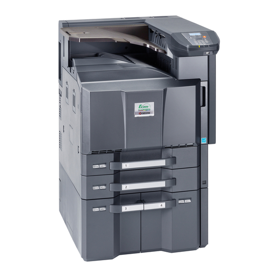
2MN/2N1 1-1-2 Parts names (1) Machine Figure 1-1-1 1. Operation panel 10. Waste toner box 2. Indicators 11. Waste toner tray 12. Front cover 3. Main tray 13. Handles 4. Job separator tray 14. Network interface connector 5. Toner container K 15. - Page 19 2MN/2N1 Figure 1-1-2 19. USB port 29. Duplex cover 20. Cassettes 1 30. MP paper width guide 21. Cassettes 2 31. Main power switch 22. Paper length guide 32. MP support Tray 23. Guide lock lever 33. MP (Multi-Purpose) tray 24.
- Page 20 2MN/2N1-1 (2) Option 3, 7 Figure 1-1-3 1. Machine 7. Side large capacity feeder 2. Paper feeder 8. 1000-sheet finisher 3. Large capacity feeder 9. 4000-sheet finisher 4. Side deck 10. Center-folding unit 5. Side multi tray 11. Mailbox 6. Side paper feeder * : The mailbox can be installed either the main unit or the 4000-sheet finisher.(Not installable at the same time) 1-1-6...
- Page 21 2MN/2N1 (3) Operation panel Figure 1-1-4 1. Message display 9. Cursor key 2. Right select key 10. OK key 3. Left select key 11. Clear key 4. Logout key 12. Print Box key 5. Menu key 13. Ready indicator 6. Back key 14.
-
Page 22: Machine Cross Section
2MN/2N1 1-1-3 Machine cross section Paper Path Figure 1-1-5 1. Cassette paper feed section 8. Drum unit Y 15. Secondary transfer/Separa- 2. MP tray paper feed section 9. Developer unit K tion sections 3. Paper conveying section 10. Developer unit M 16. -
Page 23: Installation Environment
2MN/2N1 1-2 Installation 1-2-1 Installation environment 1. Temperature: 10 to 32.5°C/50 to 90.5°F 2. Humidity: 15 to 80% RH 3. Power supply: 120 V AC, 12.0 A 220 - 240 V AC, 7.2 A 4. Power source frequency: 50 Hz ± 2%/60 Hz ± 2% 5. -
Page 24: Unpacking And Installation
2MN/2N1-1 1-2-2 Unpacking and installation (1) Installation procedure Start Unpacking Adjusting the image Removing the tapes and spacers Setting the delivery date (maintenance item U278) Installing the main tray and jobseparator tray Output an own-status report (maintenance item U000) Release of lift plate stopper Exit maintenance mode Loading paper Print out the user setting list... - Page 25 2MN/2N1 Moving the machine When moving the machine, pull out three carrying handles, and move with carrying handles and the hand- hold. Handhold Carrying handle Carrying Carrying handle handle Figure 1-2-2 *: Moving this machine is a job for four peo- ple.
- Page 26 2MN/2N1 Unpacking 120V model 21,22, 23,24,25 Figure 1-2-4 1-2-4...
- Page 27 2MN/2N1 220-240V model 21,22, 23,24,25 Figure 1-2-5 1. Machine 10. Right pad 19. Document tray 2. Outer case 11. Rear pad 20. Power cord 3. Inner case 12. Top spacer 21. Plastic bag 4. Spacer A 13. Machine cover 22. Paper size plates 5.
- Page 28 2MN/2N1 Removing the tapes 1. Remove two tapes and the protect Protect sheet sheet. Tape 2. Remove tape and the top spacer. Tapes Top spacer Figure 1-2-6 3. Remove tape and then two protect Tape sheets. 4. Remove three tapes and then protect sheet.
- Page 29 2MN/2N1 6. Open the front cover and then remove tape. Tape Figure 1-2-8 1. Remove three tapes and then remove three protect sheet. 2. Remove two tapes. Tape Protect sheet Tape Tape Tapes Figure 1-2-9 1-2-7...
- Page 30 2MN/2N1-1 3. Remove tape. Tape Figure 1-2-10 Installing the main tray and job separator tray *: When the finisher has been installed, the job separator tray and the main tray are not needed. 1. Install the main tray included by latching in two hooks and securing by one screw.
- Page 31 2MN/2N1-1 2. Raise the tray fixing plate. Hooks 3. Latch the three hooks to the job sepa- rator tray. Hook 4. Load the tray on the tray fixing board and slide it to secure. *: Make sure that the two clicks have been Jobseparator tray properly locked.
- Page 32 2MN/2N1 Loading paper 1. Squeeze the ends of the bottom of the Paper length guide paper length guide and move the guide to fit the length of the paper. Figure 1-2-14 2. Press the guide lock lever to release the lock. 3.
- Page 33 2MN/2N1 4. Align the paper flush against the right Paper side of the cassette. *: Before loading the paper, be sure that it is not curled or folded. *: Ensure that the loaded paper does not exceed the level indicated. *: Make sure that the paper length guide and the paper width guides are correctly abut with the paper.
- Page 34 2MN/2N1 5. Press the guide lock lever to lock. Guide lock lever Figure 1-2-17 6. Insert the paper size plate and the Paper media plate paper media plate. 7. Gently push the cassette back in. Paper size plate Figure 1-2-18 1-2-12...
- Page 35 2MN/2N1 Installing the toner containers 1. Open the front cover. 2. Hold the toner container vertically and hit the upper part about 3 times. Invert the toner container so that the other end is up, and hit in the same way. 3.
- Page 36 2MN/2N1 Unlocking the developer waste exit Caution Tape To ease setup, the device was shipped with the developer unit already replenished with developer. Therefore, to prevent developer from spilling during shipping, a developer shutter is equipped with the developer unit. To disengage the shutter, use the following Set up leaflet procedure: Note that if the shutter is not...
- Page 37 2MN/2N1 3. Remove a screw and slide the lever right wards. 4. Fix the lever using the screw previously removed at the right screw hole and unlock the developer waste exit. *: When the device is shipped again or removed, use the reverse procedure to lock in the developer waste exit.
- Page 38 2MN/2N1 Installing optional devices 1. Install the optional devices (job separa- tor, document finisher and/or fax kit etc.) as necessary. Installing the cassette heater (option) 1. Install the optional cassette heater as necessary (see page 1-2-21). Connect the power cord 1.
- Page 39 2MN/2N1 4. Performing LSU cleaning (see the operation guide) In the Adjust/Maint. menu screen, press cursor key to select Service Setting. Press the OK key. In the Service Setting. menu screen, press cursor key to select [LSU]. Press the OK key. A confirmation screen appears. Press [Yes] ([Left select key]).
- Page 40 2MN/2N1 2. Enter the maintenance mode by entering 10871087 using the numeric keys. (see page P.1-3-1) 3. Enter 278 using the numeric keys and press the Ok key. 4. Select [Today]. 5. Press the Ok key. The delivery date is set. 6.
- Page 41 2MN/2N1-1 (2) Shut-down To turn main power off, be sure to perform the following before turning the main power switch off. *: Before proceeding, make sure that the data lamp is turned off. *: The hard disk may be operating when the Data indicator is lit or blinking.
- Page 42 2MN/2N1-1 (3) Setting initial print modes Factory settings are as follows: Maintenance Contents Factory setting item No. U253 Switching between double and single counts DBL(A3/Ledger) U260 Selecting the timing for print counting Eject U285 Setting service status page U323 Setting abnormal temperature and humidity warning U325 Setting the paper interval Off/1...
-
Page 43: Installing The Cassette Heater (Option)
2MN/2N1 1-2-3 Installing the cassette heater (option) Cassette heater installation requires the following parts: Parts Quantity Part.No. Cassette heater set (120V) 302K994930 Cassette heater set (240V) 302K994940 Supplied parts of cassette heater set (302K994930): Parts Quantity Part.No. Cassette heater (120V) 302H794620 Wire saddle 7YZM610001++H0... - Page 44 2MN/2N1-1 Procedure 1. After confirming the data lamp is turned off, perform shut-down on the operation panel, turn power off, and unplug the power receptacle(see page P.1-2-19). 2. Pull the cassette 1 forward. Cassette slider 1 3. Draw out Cassette 1 by releasing the release lever.
- Page 45 2MN/2N1 6. Fit three wire saddles on the bottom frame of the machine. 7. Fit the cassette heater using two M3 x 8 screws. Wire saddle Wire saddles Screw Screw Cassette heater Figure 1-2-28 1-2-23...
- Page 46 2MN/2N1 8. Connect the connector of the cassette heater to the connector in the rear frame of the machine. 9. Pass the wire of the cassette heater through three wire saddles and then fasten the wire. Wire saddle Wire saddle Cassette heater Connector Figure 1-2-29...
- Page 47 2MN/2N1 12. To install Cassette 1 and Cassette 2, align the cassette slider 2 and cassette slider 1 with each other. Cassette 1, 2 13. Push the cassette in fully. Cassette slider 2 Cassette slider 1 Figure 1-2-31 1-2-25...
-
Page 48: Installing The Gigabit Ethernet Board (Option)
2MN/2N1-1 1-2-4 Installing the gigabit ethernet board (option) Gigabit ethernet board installation requires the following parts: Parts Quantity Part.No. Gigabit ethernet board 1505JV0UN0 (option) Procedure 1. After confirming the data lamp is turned off, perform shut-down on the operation panel, turn power off, and unplug the power receptacle (see page P.1-2-19). - Page 49 2MN/2N1 4. Insert the gigabit ethernet board along the groove in OPT2 and secure the board with two pins that have been removed in step 3. *: Do not directly touch the gigabit ethernet board terminal. Gigabit Hold the top and bottom of the gigabit ethernet board ethernet board, or the projection of the board to insert the gigabit ethernet board.
-
Page 50: Installing The Ic Card Reader Holder (Option)
2MN/2N1-1 1-2-5 Installing the IC card reader holder (option) IC card reader holder installation requires the following parts: Parts Quantity Part.No. IC card reader holder 1709AD0UN0 (option) Relaying USB wire 302MN46210 *1: For internal wirings only Supplied parts of IC card reader holder (1709AD0UN0): Parts Quantity Part.No. - Page 51 2MN/2N1 4. Remove two screws. Hook 5. Unhook three hooks and then remove Hooks the Left upper cover. Left upper cover Screws Left upper cover Figure 1-2-36 6. Remove screw and then remove the rear tray cover. Rear tray cover Screw Figure 1-2-37 1-2-29...
- Page 52 2MN/2N1 7. Remove seven screws and then remove the rear upper cover. Screws Screws Screws Screw Figure 1-2-38 8. Remove five screws and then remove Screw the Top cover. Screw Screw Top cover Screw Screw Figure 1-2-39 1-2-30...
- Page 53 2MN/2N1 9. Cut out the aperture plate on the upper right cover using nippers. Upper right cover Aperture Figure 1-2-40 10. Fit two clamps. Clamps Figure 1-2-41 1-2-31...
- Page 54 2MN/2N1-1 11. Fit four clamps. Clamps Clamp Figure 1-2-42 12. Release ten wire saddles. Wire holders 13. Remove two wire holders. Clamps Clamps Clamps Clamps Clamps Figure 1-2-43 1-2-32...
- Page 55 2MN/2N1-1 14. Connect the relaying USB wire to the USB wire of the IC card reader. 15. Insert the connector of the relaying USB wire to the main PWB. 16. Fix the USB wire of the IC card reader using ten wire saddles and two wire holders.
- Page 56 2MN/2N1 18. .Fix the wirings of extra portion using two clamps so that the distance of the USB power line from the clamp to the IC card reader is approximately Clamps 160mm. 160 mm IC card reader Figure 1-2-46 19. Route the IC card reader through the Upper right cover opening in the upper right cover and fix...
- Page 57 2MN/2N1 20. Remove the pin of the card reader base and then remove the card reader mount. Figure 1-2-48 21. Fit the card reader mount to the machine using two pins. Right upper cover Figure 1-2-49 1-2-35...
- Page 58 2MN/2N1 22. Refit the card reader base to card reader mount using the pin removed in step 20. Figure 1-2-50 23. Fit the card reader tray to the card reader base. Choose the direction of mounting the IC card reader according to the depth of Card reader the reader.
- Page 59 2MN/2N1 24. Mount the IC card reader on the card reader base. IC card reader Figure 1-2-52 25. Hook the two hooks of the card reader case to fit the card reader case to the card reader base. Press its top until it clicks in. Card reader case Hooks...
- Page 60 2MN/2N1-1 For external wirings Procedure 1. After confirming the data lamp is turned off, perform shut-down on the operation panel, turn power off, and unplug the power receptacle(see page P.1-2-19). 2. Remove the pin of the card reader base and then remove the card reader mount.
- Page 61 2MN/2N1 Figure 1-2-55 7. Refit the card reader base to card reader mount using the pin removed in step 2. Figure 1-2-56 8. Fit the card reader tray to the card reader base. Choose the direction of mounting the IC card reader according to the depth of Card reader the reader.
- Page 62 2MN/2N1 9. Route the USB wire of the IC card IC card reader reader through the aperture of the card reader base and mount the IC card reader on the card reader base. Aperture USB wire Figure 1-2-58 10. Hook the two hooks of the card reader case to fit the card reader case to the card reader base.
- Page 63 2MN/2N1 Clamps 11. Fit six clamps. Right side: three Rear side: three Clamps Figure 1-2-60 Clamps 12. Pass the USB wire of the IC card reader through six clamps and then fasten the wire. 13. Connect the USB wire to the machine. If the length does not suffice, use the USB wire supplied.
- Page 64 2MN/2N1 Enabling IC Card Authentication Precautions To install the optional function, you need the License Key. Please access the designated web site of your dealer or service representative, and register “Machine No.” indicated on your machine and “Product ID” indi- cated on the License Certificate supplied with the product to issue the License Key.
-
Page 65: Installing The Duct Unit (Option)
2MN/2N1-1 1-2-6 Installing the duct unit (option) Duct unit installation requires the following parts: Parts Quantity Part.No. Duct unit 302LC94530 Supplied parts of duct unit (302LC94530): Parts Quantity Part.No. Duct A Duct B Filter M3 x 8 tap-tight P screw 7BB200308H 7BB282308H M3 x 8 tap-tight P screw (black) - Page 66 2MN/2N1 3. Fit two filters to duct A. Duct A Filters Figure 1-2-63 4. Remove the screw A from the rear lower cover. Rear lower cover Screw A Figure 1-2-64 1-2-44...
- Page 67 2MN/2N1 5. Fit the duct unit to the machine using the removed screw A, M3 x 8 tap-tight P screw (black) and two M3 x 8 tap-tight S screws (black). M3 x 8 tap-tight S screws (black) M3 x 8 tap-tight P screw (black) Screw A Figure 1-2-65...
- Page 68 2MN/2N1 This page is intentionally left blank. 1-2-46...
-
Page 69: Maintenance Mode
2MN/2N1 1-3 Maintenance Mode 1-3-1 Maintenance mode The machine is equipped with a maintenance function which can be used to maintain and service the machine. (1) Executing a maintenance item Perform this operation when the panel displays Ready to print or that the cover is open. Start Press the menu key while pressing and holding the OK and down cursor keys... - Page 70 2MN/2N1 (2) Maintenance modes item list Initial setting Item Section Content of maintenance item 45ppm 55ppm General U000 Outputting an own-status report U001 Exiting the maintenance mode U002 Setting the factory default data U004 Setting the machine number U019 Displaying the ROM version Initializa- U021 Memory initializing tion...
- Page 71 2MN/2N1 Initial setting Item Section Content of maintenance item 45ppm 55ppm Drive, U053 Motor3 27/0/-30/ -18/0/-27/ paper -30/82/0/18/-30/-30/ -27/73/0/ feed and 0/0/0/0 16/-27/-27/ paper 0/0/0/0 convey- Motor4 -/28 25/22 ing sys- Motor5 0/0/14/0 Motor6 -16/0/-25/ -25/66/0/ 15/-24/-24 Motor1 Half Motor2 Half 0/0/0/34/0 0/0/0/30/0 Motor3 Half...
- Page 72 2MN/2N1 Initial setting Item Section Content of maintenance item 45ppm 55ppm High U101 Normal B/W voltage Add Color 2/2/5 Add Color 2nd -3/-3/-2/-14 Surround Correct U106 Setting the voltage for the secondary transfer Light/Normal 1st 143/134/120 150/139/128 Normal2/3 1st Light/Normal 2nd 207/155/124 220/163/128 Normal2/3 2nd...
- Page 73 2MN/2N1 Initial setting Item Section Content of maintenance item 45ppm 55ppm High U122 Checking the transfer belt unit number voltage U123 Displaying the transfer belt unit history U127 Checking/clearing the transfer count U128 Setting transfer high-voltage timing -5/0/13 -5/0/10 Developer U130 Initial setting for the developer U131 Adjusting the toner sensor control volt- Manual 150/150/150/150...
- Page 74 2MN/2N1-1 Initial setting Item Content of maintenance item Section 45ppm 55ppm Developer U157 Checking the developer drive time U158 Checking the developer count Fuser U161 Setting the fuser control temperature Warm Up 165/140/80/170/165/ 170/145/80/175/175/ 150/50/155 150/50/160 Print 170/5 175/5 Low Power Mode Mode1 Grain Mode Mode0...
- Page 75 2MN/2N1-1 Initial setting Item Section Content of maintenance item 45ppm 55ppm Mode U323 Setting abnormal temperature and setting humidity warning U325 Setting the paper interval Off/1 U327 Setting the cassette heater control U332 Setting the size conversion factor Rate Mode Level 1 Level 2 U340 Setting the applied mode...
- Page 76 2MN/2N1-1 Initial setting Item Section Content of maintenance item 45ppm 55ppm Image U486 Setting color/black and white operation Mode2 process- mode Others U901 Checking print counts by paper feed locations U903 Checking/clearing the paper jam counts U904 Checking/clearing the call for service counts U905 Checking counts by optional devices U906 Resetting partial operation control...
- Page 77 2MN/2N1 Contents of the maintenance mode items Item No. Description U000 Outputting an own-status report Description Outputs lists of the current settings of the maintenance items, and paper jam and service call occurrences. Outputs the event log or service status page. Also sends output data to the USB memory.
- Page 78 2MN/2N1-1 Item No. Description U000 Method: Send to the USB memory 1. Perform shut-down on the operation panel, turn power off (see page p.1-2-19). 2. Insert USB memory in USB memory slot. 3. Turn the main power switch on. 4. Enter the maintenance item. 5.
-
Page 79: Event Log
2MN/2N1 Item No. Description U000 Event log Event Log Printer 27/Oct/2010 08:40 Firmware version 2MN_2000.000.000 2010.10.27 [XXXXXXXX] [XXXXXXXX] [XXXXXXXX] [XXXXXXXX] (12) Paper Jam Log Counter Log Count. Event Descriprions J0000: J0041: C0000: T00: 9999999 0501.01.08.01.01 J0001: J0042: C0001: T01: 8888888 4002.01.08.01.01 J0002: J0043:... - Page 80 2MN/2N1 Item No. Description U000 Detail of event log Items Description Controller BROM version Operation panel mask version Machine serial number Paper Jam Count. Event Remembers 1 to 16 of The total page count Log code (hexadeci- occurrence. If the occur- at the time of the mal, 5 categories) rence of the previous...
- Page 81 2MN/2N1 Item No. Description U000 Items Description Paper Jam (d) Detail of paper type (Hexadecimal) cont. 01: Plain 0A: Color 15: Custom 1 02: Transparency 0B: Prepunched 16: Custom 2 03: Preprinted 0C: Envelope 17: Custom 3 04: Labels 0D: Cardstock 18: Custom 4 05: Bond 0E: Coated...
- Page 82 2MN/2N1 Item No. Description U000 Items Description Service Call Count. Service Code Remembers 1 to 8 The total page Self diagnostic error code of occurrence of self count at the time of (See page 1-4-27) diagnostics error. If the self diagnostics the occurrence of error.
- Page 83 2MN/2N1 Item No. Description U000 Items Description (12) Counter Log (f) Paper jam (g) Self diagnostic (h) Maintenance item error replacing Comprised of Indicates the log Indicates the log Indicates the log coun- three log coun- counter of paper counter of self diag- ter depending on the ters including jams depending on...
-
Page 84: Service Status Page
2MN/2N1-1 Item No. Description U000 Service status page (1) Service Status Page 27/10/2011 12:00 Printer Firmware version 2MN_2000.001.001 2011.10.27 [XXXXXXXX] [XXXXXXXX] [XXXXXXXX] Controller Information Memory status Standard Size 1.0 GB Option Slot 1.0 GB Total Size 2.0 GB Time (10) Local Time Zone +01:00 Amsterdam (11) - Page 85 2MN/2N1-1 Item No. Description U000 Service status page (2) Service Status Page 27/10/2011 12:00 Printer Firmware version 2MN_2000.001.001 2011.10.27 [XXXXXXXX] [XXXXXXXX] [XXXXXXXX] Engine Information Send Information (30) (32) NVRAM Version _1F31225_1F31225 Date and Time 11/10/27 (33) Address (31) MAC Address 00:C0:EE:D0:01:0D (34) (35) (36)
- Page 86 2MN/2N1 Item No. Description U000 Detail of service status page Description Supplement Firmware version System date Engine soft version Engine boot version Operation panel mask version Machine serial number Standard memory size Option memory size Total memory size (10) Local time zone (11) Report output date Day/Month/Year hour:minute...
- Page 87 2MN/2N1 Item No. Description U000 Description Supplement (28) RP code Code the engine software version and the date of the previous update. (29) RP code Code the main software version and the date of the previous update. (30) NV RAM version _ 1F3 1225 _ 1F3 1225 (a) (b) (d) (e)
- Page 88 2MN/2N1 Item No. Description U000 Description Supplement (39) Panel lock information F00: Off/F01: Partial lock 1/F02:Partial lock 2 F03: Partial lock 3/F04: Full lock (40) USB information U00: Not installed/U01: Full speed/U02: Hi speed (41) Paper handling information 0: Paper source unit select/1: Paper source unit (42) Color printing double count 0: All single counts...
- Page 89 2MN/2N1-1 Item No. Description U000 Description Supplement (60) Calibration information Black/Cyan/Magenta/Yellow (61) Calibration information (62) Calibration information (63) Calibration information (64) RFID information (65) RFID reader/writer version infor- mation (66) Option messege version (67) Color table version for printer (68) Color table 2 version for printer (69) Maintenance information...
- Page 90 2MN/2N1-1 Item No. Description U001 Exiting the maintenance mode Description Exits the maintenance mode and returns to the normal print mode. Purpose To exit the maintenance mode. Method 1. Press the OK key. The normal print mode is entered. U002 Setting the factory default data Description Restores the machine conditions to the factory default settings.
- Page 91 2MN/2N1-1 Item No. Description U004 Setting the machine number Description Sets or displays the machine number. Purpose To check or set the machine number. Method 1. Press the OK key. If the machine serial number of engine PWB matches with that of main PWB Display Description Machine No.
- Page 92 2MN/2N1 Item No. Description U010 Setting the maintenance mode ID Description Sets the maintenance mode ID. Purpose Modify maintenance mode ID for more security. Method 1. Press the OK key. Display Description New ID Enter a new 8-digit ID New ID(Reconfirm) Enter a new 8-digit ID (to confirm) Initialize Initialize the ID...
- Page 93 2MN/2N1 Item No. Description U019 Displaying the ROM version Description Displays the part number of the ROM fitted to each PWB. Purpose To check the part number or to decide, if the newest version of ROM is installed. Method 1. Press the OK key. The ROM version are displayed. 2.
- Page 94 2MN/2N1-1 Item No. Description U019 Completion Press the Back key. The screen for selecting a maintenance item No. is displayed. U021 Memory initializing Description Initializes all settings, except those pertinent to the type of machine, namely each counter, ser- vice call history and mode setting. Also initializes backup RAM according to region specification selected in maintenance item U252 Setting the destination.
- Page 95 2MN/2N1-1 Item No. Description U024 HDD formatting Description Initializes the hard disk. Purpose To initialize the hard disk when replacing the hard disk after shipping. Caution In addition, the following settings are also initialized by initializing the hard disk. System menu (user login administration, job accounting and document box etc.) When fully formatted, the following pre-installed software are removed.
- Page 96 2MN/2N1-1 Item No. Description U030 Checking the operation of the motors Description Drives each motor. Purpose To check the operation of each motor. Method 1. Press the OK key. 2. Select the motor to be operated. 3. Press the OK key. The operation starts. Display Description Feed...
- Page 97 2MN/2N1-1 Item No. Description U031 Checking switches and sensors for paper conveying Description Displays the on-off status of each paper detection switch or sensor on the paper path. Purpose To check if the switches and sensors for paper conveying operate correctly. Method 1.
- Page 98 2MN/2N1 Item No. Description U032 Checking the operation of the clutches Description Turns each clutch on. Purpose To check the operation of each clutch. Method 1. Press the OK key. 2. Select [Motor On] or [Motor Off]. Display Description Motor On is turned on Motor Motor Off...
- Page 99 2MN/2N1-1 Item No. Description U033 Checking the operation of the solenoids Description Turns each solenoid on. Purpose To check the operation of each solenoid. Method 1. Press the OK key. 2. Select [Motor On] or [Motor Off]. Display Description Motor On is turned on Motor Motor Off...
- Page 100 2MN/2N1-1 Item No. Description U034 Adjusting the print start timing Description Adjusts the leading edge registration or aligns the center line. Purpose Make the adjustment if there is a regular error between the leading edges of the print image. Make the adjustment if there is a regular error between the center lines of the print image. Method 1.
- Page 101 2MN/2N1-1 Item No. Description U034 Adjustment: Leading edge registration adjustment 1. Press the menu key. 2. Press the OK key to output a test pattern. 3. Select the item to be adjusted. [LSU Out Top] Setting Initial Change in Display Description range setting...
-
Page 102: Display Description
2MN/2N1-1 Item No. Description U034 4. Change the setting value using the numeric keys. * : Use the cursor keys to change the decimal digits. For output example 1, increase the value. For output example 2, decrease the value. Leading edge registration (20 ±... - Page 103 2MN/2N1 Item No. Description U034 5. Change the setting value using the numeric keys. For output example 1, increase the value. For output example 2, decrease the value. Center line of printing (within ± 2.0 mm) Correct image Output Output example 1 example 2 Figure 1-3-5...
- Page 104 2MN/2N1 Item No. Description U037 Checking the operation of the fan motors Description Drives each fan motor. Purpose To check the operation of each fan motor. Method 1. Press the OK key. 2. Select the fan motor to be operated. 3.
- Page 105 2MN/2N1-1 Item No. Description U051 Adjusting the deflection in the paper Description Adjusts the deflection in the paper at the registration roller. Purpose Make the adjustment if the leading edge of the print image is missing or varies randomly, or if the print paper is Z-folded.
- Page 106 2MN/2N1-1 Item No. Description U051 [LSU Out Top B/W] Initial setting Setting Display Description range 45ppm 55ppm MPT(L) Paper feed from MP tray -30 to 20 Cass(L) Paper feed from cassette -30 to 20 Dup(L) Duplex mode (second) -30 to 20 MPT(S) Paper feed from MP tray -30 to 20...
- Page 107 2MN/2N1 Item No. Description U052 Setting the fuser motor control Description Enters the sensor data values described on the supplied sheet provided when the loop sensor is replaced and performs correction processing for the fuser motor. Purpose To perform when replacing the loop sensor or paper conveying unit. Method 1.
- Page 108 2MN/2N1 Item No. Description Setting: [Loop Sensor Control] 1. Select the item. 2. Select On or Off. Display Description Initial setting No.1 Sensor detection On/Off setting at 125 to 250 mm from the top of paper No.2 Sensor detection On/Off setting at 250 to 290 mm from the top of paper No.3 Sensor detection On/Off setting at 300 to 330 mm from...
- Page 109 2MN/2N1 Item No. Description U053 Setting the adjustment of the motor speed Description Performs fine adjustment of the speeds of the motors. Purpose Basically, the setting need not be changed. Modify settings by interlock setting only if faulty images occur. Method 1.
- Page 110 2MN/2N1 Item No. Description U053 Setting: [Motor2] 1. Select the item to be adjusted. Initial setting Setting Display Description range 45ppm 55ppm Dev(K) Developer motor K -5000 to 5000 0 (DEVM-K) Dev(CMY) Developer motor MCY -5000 to 5000 0 (DEVM-MCY) Trans Transfer motor (TRM) -5000 to 5000 0...
- Page 111 2MN/2N1 Item No. Description U053 Setting: [Motor4] 1. Select the item to be adjusted. Initial setting Setting Display Description range 45ppm 55ppm Drum B/W Drum motor K (DRM-K) in -5000 to 5000 - black/white mode Drum- Drum motor K (DRM-K) in -5000 to 5000 28 Mono K monochrome mode...
- Page 112 2MN/2N1 Item No. Description U053 Setting: [Motor1 Half] 1. Select the item to be adjusted. Setting Initial Display Description range setting Drum(K) Drum motor K (DRM-K) in half speed -5000 to 5000 Setting: [Motor2 Half] 1. Select the item to be adjusted. Initial setting Setting Display...
- Page 113 2MN/2N1 Item No. Description U053 Initial setting Setting Display Description range 45ppm 55ppm Duplex motor 1 (DUM1) -5000 to 5000 -60 in half speed Duplex motor 2 (DUM2) -5000 to 5000 -60 in half speed Setting: [Motor1 3/4] 1. Select the item to be adjusted. Setting Initial Display...
- Page 114 2MN/2N1 Item No. Description U053 Setting: [Motor3 3/4] 1. Select the item to be adjusted. Initial setting Setting Display Description range 45ppm 55ppm Eject motor (EM) at 3/4 -5000 to 5000 35 times of line speed Fixing Fuser motor (FUM) at 3/4 -5000 to 5000 0 times of line speed Brg1...
- Page 115 2MN/2N1 Item No. Description U059 Setting fan mode Description Specifies mode for developer fan motors. Purpose Handling the lowering density [to suppress thermal stresses owing to the heated toner] Method 1. Press the OK key. 2. Select the mode. Display Description Sets threshold temperature at which developer fan motors oper- ate.
- Page 116 2MN/2N1-1 Item No. Description U089 Outputting a MIP-PG pattern Description Selects and outputs the MIP-PG pattern created in the machine. Purpose To check machine status when adjusting image printing, using MIP-PG pattern output. Method 1. Press the OK key. 2. Select the MIP-PG pattern to be output and press the OK key. Display Description Purpose...
- Page 117 2MN/2N1-1 Item No. Description U100 Adjusting main high voltage Description Controls the charger roller voltage to optimize the surface potential. Purpose To change the setting value to adjust the image if an image failure (background blur, etc.) occurs. Method 1. Press the OK key. 2.
- Page 118 2MN/2N1 Item No. Description U100 Displaying: [Set DC Bias] 1. The current setting is displayed. Display Description DC1(C) Main charger DC bias for cyan (full speed) DC1 Half(C) Main charger DC bias for cyan (half speed) DC1(M) Main charger DC bias for magenta (full speed) DC1 Half(M) Main charger DC bias for magenta (half speed) DC1(Y)
- Page 119 2MN/2N1 Item No. Description U100 Setting: [Set Charger Freq] 1. Select the item to be set. 2. Change the value using the numeric keys.ll Initial setting Setting Display Description range 45ppm 55ppm Generally Main charger frequency 7500 to 8807 11022 11280 B/W* Main charger frequency in...
- Page 120 2MN/2N1 Item No. Description U101 Setting the voltage for the primary transfer Description Sets the control voltage for the primary transfer. Purpose To change the setting when any density problems, such as too dark or light, occur. Setting 1. Press the OK key. 2.
- Page 121 2MN/2N1-1 Item No. Description U101 Setting: [Add Color 2nd] 1. Select the item to be set. 2. Change the value using the numeric keys.l Setting Initial Display Description range setting Addition value for the second side (cyan) -127 to 127 Addition value for the second side (magenta) -127 to 127 Addition value for the second side (yellow)
- Page 122 2MN/2N1-1 Item No. Description U106 Setting the voltage for the secondary transfer Description Sets the control voltage for the secondary transfer depending on each paper type. Purpose To change the setting when any density problems, such as too dark or light, occur. Method 1.
- Page 123 2MN/2N1 Item No. Description U106 [1st] Initial setting Setting Display Description range 45ppm 55ppm Width=105 105 mm wide 0 to 255 Width=210 210 mm wide 0 to 255 Width=297 297 mm wide 0 to 255 [2nd] Initial setting Setting Display Description range 45ppm...
- Page 124 2MN/2N1 Item No. Description U106 Setting: [Normal2/3] 1. Select the item to be set. Display Description Control voltage for the transfer bias for the first side (full speed) Control voltage for the transfer bias for the second side (full speed) 1st 3/4(Gloss) Control voltage for the transfer bias for the first side at 3/4 times of line speed...
- Page 125 2MN/2N1 Item No. Description U106 [2nd 3/4(Gloss)] Initial setting Setting Display Description range 45ppm 55ppm Width=105 105 mm wide 0 to 255 Width=210 210 mm wide 0 to 255 Width=297 297 mm wide 0 to 255 [1st B/W] Initial setting Setting Display Description...
- Page 126 2MN/2N1 Item No. Description U106 [2nd 3/4] Initial setting Setting Display Description range 45ppm 55ppm Width=105 105 mm wide 0 to 255 Width=210 210 mm wide 0 to 255 Width=297 297 mm wide 0 to 255 4. Press the OK key. The value is set. Setting: [Heavy4/5] 1.
- Page 127 2MN/2N1-1 Item No. Description U106 Setting: [Bias] 1. Select the item to be set. 2. Change the value using the numeric keys. Initial setting Setting Display Description range 45ppm 55ppm Reverse Transfer reverse bias 0 to 255 (full speed) Reverse Transfer reverse bias 0 to 255 Half...
- Page 128 2MN/2N1-1 Item No. Description U107 Setting the transfer cleaning voltage Description Sets the cleaning control voltage for transfer belt unit. Purpose Change settings if an offset has occurred due to the failure of cleaning the transfer belt. Method 1. Press the OK key. 2.
- Page 129 2MN/2N1 Item No. Description U108 Setting separation shift bias Description Adjusts output of separation shift bias and ON/OFF timing. Purpose To set when the separated malfunction of the paper occurs. Method 1. Press the OK key. 2. Select the item to be set. Display Description Output...
- Page 130 2MN/2N1-1 Item No. Description U108 Setting: [Output 3/4 / Output B/W] 1. Select the item to be set. 2. Change the setting value using the numeric keys or numeric key. Initial setting Setting Display Description range Output Output B/W* Light 1st Separation shift bias for the first side on 0 to 255 paper with thickness 52 to 64 g/m...
- Page 131 2MN/2N1 Item No. Description U110 Checking the drum count Description Displays the drum counts for checking. Purpose To check the drum status. Method 1. Press the OK key. The current drum counts is displayed. Display Description Drum count value for cyan Drum count value for magenta Drum count value for yellow Drum count value for black...
- Page 132 2MN/2N1 Item No. Description U117 Checking the drum number Description Displays the drum number. Purpose To check the drum number. Method 1. Press the OK key. The drum number is displayed. Display Description Cyan drum number Magenta drum number Yellow drum number Black drum number Completion Press the Back key.
- Page 133 2MN/2N1-1 Item No. Description U118 Displaying the drum history Description Displays the past record of machine number and the drum counter. Purpose To check the count value of machine number and the drum counter. Method 1. Press the OK key. 2.
- Page 134 2MN/2N1 Item No. Description U122 Checking the transfer belt unit number Description Displays the number of the transfer belt unit for checking. Purpose To check the number of the transfer belt. Method 1. Press the OK key. The current number of the transfer belt is displayed. Completion Press the Back key.
- Page 135 2MN/2N1 Item No. Description U127 Checking/clearing the transfer count Description Displays and clears the counts of the transfer counter. Purpose To check the count or drive time after replacement of the transfer belt unit or transfer roller. Also to clear the counts after replacing transfer roller. Method 1.
- Page 136 2MN/2N1 Item No. Description U128 Setting transfer high-voltage timing Description Adjusts the ON/OFF timing of transfer high-voltage output. Purpose Basically, the setting need not be changed. If any problem such as faulty images or dirt on the back surface occurs, change the setting. Method 1.
- Page 137 2MN/2N1 Item No. Description U131 Adjusting the toner sensor control voltage Description Adjusts the toner sensor control voltage. Purpose If control values are not correctly retrievable due to the EEPROM of the developer unit failure, etc., use manual adjustment and obtain a temporary control value. Method 1.
- Page 138 2MN/2N1 Item No. Description U131 Setting: [Mode] 1. Select the item to be set. Display Description Manual Toner sensor control voltage manual adjustment Auto Toner sensor control voltage auto adjustment Initial setting: Auto 2. Press the OK key. The value is set. Completion Press the Back key.
- Page 139 2MN/2N1 Item No. Description U135 Checking toner motor operation Description Drives toner motors. Purpose To check the operation of toner motors. Remarks When driving the toner motors long time or several times, developer section becomes the toner full and is locked. Method 1.
- Page 140 2MN/2N1-1 Item No. Description U139 Displaying the temperature and humidity outside the machine Description Displays the detected temperature and humidity outside the machine. Purpose To check the temperature and humidity outside the machine. Method 1. Press the OK key. 2. Select the item. Display Description Ext/Int...
- Page 141 2MN/2N1 Item No. Description U140 Displaying developer bias Description Displays and changes various developer bias value. Purpose To check or changes the developer bias value. Method 1. Press the OK key. 2. Select the item to be set. Display Description Sleeve DC Developer sleeve roller DC bias Sleeve AC...
- Page 142 2MN/2N1 Item No. Description U140 Setting: [Sleeve AC] 1. Select the item to be set. 2. Change the setting value using the numeric keys. Initial setting Setting Display Description range 45ppm 55ppm Developer sleeve roller AC bias 0 to 255 for cyan Developer sleeve roller AC bias 0 to 255...
- Page 143 2MN/2N1 Item No. Description U140 Setting: [Mag AC] 1. Select the item to be set. 2. Change the setting value using the numeric keys. Initial setting Setting Display Description range 45ppm 55ppm Developer magnet roller AC bias 0 to 255 for cyan Developer magnet roller AC bias 0 to 255...
- Page 144 2MN/2N1-1 Item No. Description U140 Setting: [Mag Duty] 1. Select the item to be set. 2. Change the setting value using the numeric keys. Initial setting Setting Display Description range 45ppm 55ppm Normal Developer magnet roller duty 0 to 99 B/W* Developer magnet roller duty in 0 to 99...
- Page 145 2MN/2N1-1 Item No. Description U140 Method: [High Altitude] 1. Select Mode1 or Mode2. Display Description Mode1 Execute AC calibration by normal bias control Mode2 If print density is low in an installation at high altitude, execute calibration by fixing the bias potential. Initial setting: Mode1 2.
- Page 146 2MN/2N1 Item No. Description U147 Setting for toner applying operation Description Sets the mode for removing charged toner in the developing unit (T7 control: Toner applying operation). Defines the action that the toner accumulated on the developer blade is sent back in the developer unit (done by the vibration motor).
- Page 147 2MN/2N1-1 Item No. Description U147 Setting: [Interval Number] 1. Select the item to be set. 2. Change the setting value using the numeric keys. Setting Initial Display Description range setting Print(Normal) During continuous printing (Normal environ- 10 to 500 ment) Print(H/H) During continuous printing (High humidity 10 to 200...
- Page 148 2MN/2N1 Item No. Description U155 Checking sensors for toner Description Displays the toner sensor output value. Purpose To check the output value for each color when any image problems occur. Method 1. Press the OK key. 2. Select the item to be display. Display Description Waste Toner...
- Page 149 2MN/2N1 Item No. Description U156 Setting the toner replenishment level Description Sets the toner replenishment level for each color. Purpose To change settings according to the original image. Method 1. Press the OK key. 2. Select the item to be set. Display Description Supply...
- Page 150 2MN/2N1 Item No. Description U157 Checking the developer drive time Description Displays the developer drive time for checking a figure, which is used as a reference when cor- recting the toner control. Purpose To check the developer drive time after replacing the developer unit. Method 1.
- Page 151 2MN/2N1 Item No. Description U161 Setting the fuser control temperature Description Changes the fuser control temperature. Purpose Normally no change is necessary. However, can be used to prevent curling or creasing of paper, or solve a fuser problem on thick paper. Method 1.
- Page 152 2MN/2N1-1 Item No. Description U161 Setting: [Print] 1. Select the item to be set. 2. Change the setting value using the numeric keys. Initial setting Setting Display Description range 45ppm 55ppm F.S.Print(C) Temperature at maximum 130 to 200 print speed (Center) (°C) Dup Shift(C) Temperature at duplex...
- Page 153 2MN/2N1-1 Item No. Description U167 Checking/clearing the fuser count Description Displays and clears the fuser count for checking. Purpose To check the fuser count or drive time after replacement of the fuser unit. Also to clear the counts after replacing unit. Method 1.
- Page 154 2MN/2N1 Item No. Description U199 Displaying fuser heater temperature Description Displays the detected fuser temperature. Purpose To check the fuser temperature. Method 1. Press the OK key. The fuser temperature is displayed. Display Description Heat Edge1 Heat roller edge temperature (°C) Heat Edge2 Heat roller edge temperature (°C) Heat Center...
- Page 155 2MN/2N1-1 Item No. Description U208 Setting the paper size for the side deck Description Sets the size of paper used in side deck. Purpose To change the setting when installing the side deck or the size of paper used in the side deck is changed.
- Page 156 2MN/2N1-1 Item No. Description U221 Setting the USB host lock function Description Specifies ON/OFF the USB host lock function. Setting this to ON causes the machine to be unable to recognize the device connected to the USB host. Purpose Set according to the preference of the user. Method 1.
- Page 157 2MN/2N1-1 Item No. Description U234 Setting punch destination Description Sets the destination of punch unit of 1000-sheet finisher or 4000-sheet finisher. Purpose To be set when installing a different punch unit from the destination of the machine. Setting 1. Press the OK key. 2.
- Page 158 2MN/2N1-1 Item No. Description U237 Setting finisher stack quantity Description Sets the number of sheets of each stack on the main tray and on the middle tray in 4000-sheet finisher. Purpose To change the setting when a stack malfunction has occurred. Method 1.
- Page 159 2MN/2N1-1 Item No. Description U240 Checking the operation of the finisher Description Turns each motor and solenoid of 1000-sheet finisher or 4000-sheet finisher ON. Purpose To check the operation of each motor and solenoid of the 1000-sheet finisher or 4000-sheet fin- isher.
- Page 160 2MN/2N1 Item No. Description U240 Display Description EjectUnlock(Fix) DF eject release motor (DFERM) fixed drive position EjectUnlock(Full) DF eject release motor (DFERM) full-open drive position Punch Punch motor (PUM) is turned on Punch Move Punch slide motor (PUSLM) is turned on Method: [Solenoid] 1.
- Page 161 2MN/2N1-1 Item No. Description U241 Checking the operation of the switches of the finisher Description Displays the status of each switches and sensors of 1000-sheet finisher or 4000-sheet finisher. Purpose To check the operation of each switches and sensors of the 1000-sheet finisher or 4000-sheet finisher.
- Page 162 2MN/2N1-1 Item No. Description U241 Display Description Switch 3 0 0 0 0 0 0 0 1 First digit: DF middle tray sensor (DFMTS) Second digit: DF side registration sensor 1 (DFSRS1) Third digit: DF side registration sensor 2 (DFSRS2) Fourth digit: DF bundle discharge sensor (DFBDS) Fifth: DF adjustment sensor (DFADS) Sixth: DF paddle sensor (DFPDS)
- Page 163 2MN/2N1-1 Item No. Description U241 Method: [Booklet] 1. Turn each switch or sensor on and off manually to check the status. When a switch/sensor is detected to be in the ON position, the display for that switch/sensor will be “1”. Display Description Switch 1...
- Page 164 2MN/2N1-1 Item No. Description U246 Setting the finisher Description Provides various settings for the 1000-sheet finisher or 4000-sheet finisher, if furnished. Purpose 1. Adjustment of registration stop timing in punch mode Adjust if skewed paper conveying occurs or if the print paper is Z-folded in punch mode. 2.
- Page 165 2MN/2N1 Item No. Description U246 Setting: [Punch Regist] 1. Select [Punch Regist]. 2. Change the setting value using the numeric keys. Description Setting Initial Change in range setting value per step Adjustment of registration stop timing -20 to 20 0.25 mm If skewed paper conveying occurs (sample 1), increase the setting value.
- Page 166 2MN/2N1 Item No. Description U246 Setting: [Punch Width] 1. Select [Punch Width]. 2. Change the setting value using the numeric keys. Description Setting Initial Change in range setting value per step Adjustment of the punch center position timing -4 to 4 0.52 mm If the punch hole is too close to the front of the machine, increase the setting value.
- Page 167 2MN/2N1-1 Item No. Description U246 Setting: [Staple HP] 1. Select [Staple HP]. 2. Change the setting value using the numeric keys. Description Setting Initial Change in range setting value per step Adjustment of front and back stapling home position -15 to 15 0.19 mm When staple positions are off toward the front side of the machine (sample 1), increase the setting value.
- Page 168 2MN/2N1 Item No. Description U246 Setting: [WidthUp HP/WidthDown HP] 1. Select [Width Up HP] or [Width Down HP]. 2. Change the setting value using the numeric keys. Description Setting Initial Change in range setting value per step Adjustment of upper side registration home position -15 to 15 0.34 mm Adjustment of lower side registration home position -15 to 15...
- Page 169 2MN/2N1 Item No. Description U246 Setting: [Booklet Pos] 1. Select [Booklet Pos1], [Booklet Pos2] or [Booklet Pos3]. 2. Change the setting value using the numeric keys. Description Setting Initial Change in range setting value per step Adjustment of center folding position for A4/Letter size -15 to 15 0 0.32 mm Adjustment of center folding position for B4/Legal size...
- Page 170 2MN/2N1 Item No. Description U247 Setting the paper feed device Description Turns on motor and clutches of paper feeder device. Purpose To check the operation of motor and clutches of paper feed device. Method 1. Press the OK key. 2. Select the paper feed device. Display Description Paper feeder...
- Page 171 2MN/2N1 Item No. Description U247 Method: [LCF/Side LCF] 1. Press the OK key. 2. Select [Motor] or [Device]. 1. Select the item to be operated using the Left/Right Select keys Display Description Motor PF paper feed motor (PFPFM) is turned off PF paper feed motor (PFPFM) is turned on Device C1 Clutch...
- Page 172 2MN/2N1 Item No. Description U247 Method: [SMT] 1. Press the OK key. 2. Select [Motor] or [Device]. 1. Select the item to be operated using the Left/Right Select keys Display Description Motor SM paper feed motor (SMPFM) is turned off SM paper feed motor (SMPFM) is turned on Device C1 Clutch...
- Page 173 2MN/2N1 Item No. Description U251 Checking/clearing the maintenance counter Description Displays and clears or changes the maintenance count. Purpose To verify the maintenance counter count. Also to clear the count during maintenance service. Setting 1. Press the OK key. 2. Select the item to be changed. 3.
- Page 174 2MN/2N1-1 Item No. Description U252 Setting the destination Description Switches the operations and screens of the machine according to the destination. Purpose To be executed after initializing the backup RAM, in order to return the setting to the value before replacement or initialization.
- Page 175 2MN/2N1 Item No. Description U253 Switching between double and single counts Description Switches the count system for the total counter and other counters for every color mode. Purpose Used to select, according to the preference of the user, if A3/Ledger paper is to be counted as one sheet (single count) or two sheets (double count).
- Page 176 2MN/2N1-1 Item No. Description U260 Selecting the timing for print counting Description Changes the print count timing for the total counter and other counters. Purpose To be set according to user request. Setting 1. Press the OK key. 2. Select the print count timing. Display Description Feed...
- Page 177 2MN/2N1 Item No. Description U271 Setting the page count Description Banner counting Purpose To change when modifying counting Banner Setting 1. Press the OK key. 2. Select the item. 3. Change the setting value using the numeric keys. Display Description Setting Initial range...
- Page 178 2MN/2N1 Item No. Description U285 Setting service status page Description Determines displaying the print coverage report on reporting. Purpose According to user request, changes the setting. Setting 1. Press the OK key. 2. Select On or Off. Display Description Displays the print coverage Not to display the print coverage Initial setting: On 3.
- Page 179 2MN/2N1 Item No. Description U325 Setting the paper interval Description Determines the interval between pages and the toner replenishment amount when printing pages with high print coverage. Purpose Modify the settings only if a spotted background or uneven density appears when printing pages with high print coverage.
- Page 180 2MN/2N1-1 Item No. Description U327 Setting the cassette heater control Description Sets the cassette heater control. Purpose To change the setting according to the machine installation environment. Setting 1. Press the OK key. 2. Select On or Off. Display Description Mode1 Set to On at 65% RH (during sleep mode or in ready state) Mode2...
- Page 181 2MN/2N1-1 Item No. Description U332 Setting the size conversion factor Description Rate: Sets the coefficient of nonstandard sizes in relation to the A4/Letter size. The coefficient set here is used to convert the black ratio in relation to the A4/Letter size and to print the service status page.
- Page 182 2MN/2N1-1 Item No. Description U340 Setting the applied mode Description Allocates memory to ensure that there is sufficient memory available for the printer to use as a working area. Purpose Modify the memory allocation if insufficient memory for transparency support or XPS direct print- ing occurs.
- Page 183 2MN/2N1-1 Item No. Description U345 Setting the value for maintenance due indication Description Sets when to display a message notifying that the time for maintenance is about to be reached, by setting the number of prints that can be made before the current maintenance cycle ends. When the difference between the number of prints of the maintenance cycle and that of the main- tenance count reaches the set value, the message is displayed.
- Page 184 2MN/2N1-1 Item No. Description U460 Adjusting the conveying sensor Description Compensates the threshold value of the side multi tray’s multi feed sensor. Purpose If more than one sheet is fed at a time, modify the threshold depending on the environment. Method 1.
- Page 185 2MN/2N1 Item No. Description Setting: [On/Off Config] U460 1. Select On or Off. Display Description Multi feed sensor is enabled Multi feed sensor is disabled Initial setting: Off 2. Press the OK key. The setting is set. Completion Press the Back key. The screen for selecting a maintenance item No. is displayed. 1-3-117...
- Page 186 2MN/2N1 Item No. Description U464 Setting the ID correction operation Description Turns ID correction (calibration) on or off. Also, this allows individual settings for calibration oper- ation. Purpose Implements various settings of calibration when poor image quality is caused or to allow various settings of calibration depending on the user preference.
- Page 187 2MN/2N1 Item No. Description U464 Setting: [Time Interval] 1. Change the setting value using the numeric keys. Setting Initial Display Description range setting Time(sec) Setting the interval time of calibration 0 to 9999 (s) 2. Press the OK key. The value is set. Setting: [Mode] 1.
- Page 188 2MN/2N1 Item No. Description U464 Setting: [Leaving Time] 1. Change the setting value using the numeric keys. Initial Display Description Setting range setting Time(min) Setting the standard time of sleep mode 0 to 480 (min) 2. Press the OK key. The value is set. Setting: [Driving Time] 1.
- Page 189 2MN/2N1 Item No. Description U464 Setting: [Print Rate(B/W)] 1. Change the setting value using the numeric keys. Setting Initial Display Description range setting Threshold Proportion of black/white printing 0 to 100 (%) 2. Press the OK key. The value is set. Method: [Calib] 1.
- Page 190 2MN/2N1 Item No. Description U465 Displaying: [TCOUNT] Select [TCOUNT]. The current value is displayed. Display Description Before(C) Developer bias control value for cyan before ID correction Before(M) Developer bias control value for magenta before ID correction Before(Y) Developer bias control value for yellow before ID correction Before(K) Developer bias control value for black before ID correction After(C)
- Page 191 2MN/2N1 Item No. Description U465 Displaying: [Stress] 1. Select [Stress]. The current value is displayed. Display Description Front Durability of the belt (front) Rear Durability of the belt (rear) Completion Press the Back key. The screen for selecting a maintenance item No. is displayed. 1-3-123...
- Page 192 2MN/2N1 Item No. Description U467 Setting the color registration adjustment Description Sets the color registration adjustment and transfer belt speed correction. Also, determines the conditions by which color registration correction is executed depending on the LSU temperature. Purpose If color variance is uneven due to a sensor failure, etc., turn this off and temporarily make a man- ual adjustment.
- Page 193 2MN/2N1 Item No. Description U468 Checking the color registration data Description Displays the color registration correction data and transfer belt speed correction data. Purpose To check the corresponding data. Method 1. Press the OK key. 2. Select the item to be reference. 3.
- Page 194 2MN/2N1-1 Item No. Description U468 Completion Press the Back key. The screen for selecting a maintenance item No. is displayed. U469 Adjusting the color registration Description Performs the color registration correction and transfer belt speed correction. Purpose To perform when replacing the transfer belt unit or laser scanner unit. Method * : Before excuting this mode, the U464 Calib mode must be executed.
- Page 195 2MN/2N1 Item No. Description U469 Codes Descrip- Codes Descrip- tion tion CH-1 MH-5 CH-2 MH-6 CH-3 MH-7 CH-4 MV-3 CH-5 YH-1 CH-6 YH-2 CH-7 YH-3 CV-3 YH-4 MH-1 YH-5 MH-2 YH-6 MH-3 YH-7 MH-4 YV-3 5. Press the OK key to finalize the value. 6.
- Page 196 2MN/2N1 Item No. Description U469 Method: [Belt Initialize] 1. Select [Execute]. 2. Press the OK key. Transfer belt speed correction starts. Method:[Belt Check] 1. Select [Mode]. 2. Change the setting value using the numeric keys. Display Description Angle Display of cam position Belt Position Display of belt position Mode...
- Page 197 2MN/2N1 Item No. Description U485 Setting the color table Description Modify and install the color table. Purpose Perform the procedure to modify the color table. Method. 1. Press the OK key. 2. Select the item. Press the OK key. Display Description Color Table 1(Prn) Setting the printer color table (Default)
- Page 198 2MN/2N1-1 Item No. Description U486 Setting color/black and white operation mode Description When color and B/W documents are mixed, sets operation mode after a color document is detected. Purpose Mode:To ensure productivity when printing color and B/W documents in ACS mode, select Mode3.
- Page 199 2MN/2N1-1 Item No. Description U486 Setting: [Permission] 1. Select On or Off. Display Description Black and white printing (3 colors are released)* Color printing (4 colors are latched in) Initial setting: Off * : Enable this setting if color background printing has occurred when printing on envelopes.Note jitter could result.
- Page 200 2MN/2N1-1 Item No. Description U901 Checking print counts by paper feed locations Description Displays or clears paper feed counts by paper feed locations. Performs backup when the counters on the engine PWB and PF main PWB do not match. Purpose To check the time to replace consumable parts.
- Page 201 2MN/2N1-1 Item No. Description U901 1. Select the paper feed location. 2. Select engine counter values when changing the PF main PWB. Backup the engine counter values to PF. Select PF counter values when changing the paper feed unit. Backup the PF counter values to engine. 3.
- Page 202 2MN/2N1 Item No. Description U903 Checking/clearing the paper jam counts Description Displays or clears the jam counts by jam locations. Purpose To check the paper jam status. Also to clear the jam counts after replacing consumable parts. Method 1. Press the OK key. 2.
- Page 203 2MN/2N1-1 Item No. Description U903 Detail of history of paper jams Maintenance Report Printer 17/Apr/2011 08:40 Firmware version 2MN_2000.000.000 2011.04.17 [XXXXXXXX] [XXXXXXXX] [XXXXXXXX] Machine No.: SPXXX00001 Life Count : 001234 Paper Jam Log 2011.12.12 JAM0000 JAM0100 JAM0101 JAM0110 JAM0111 JAM0112 JAM0131 JAM0210 Figure 1-3-17...
- Page 204 2MN/2N1 Item No. Description U904 Checking/clearing the call for service counts Description Displays or clears the service call code counts by types. Purpose To check the service call code status by types. Also to clear the service call code counts after replacing consumable parts. Method 1.
- Page 205 2MN/2N1-1 Item No. Description U904 Detail of history of service counts Maintenance Report Printer 17/Apr/2011 08:40 Firmware version 2MN_2000.000.000 2011.04.17 [XXXXXXXX] [XXXXXXXX] [XXXXXXXX] Machine No.: SPXXX00001 Life Count : 001234 Paper Jam Log 2011.12.12 JAM0000 Service Call Log 2011.12.12 C0630 C1000 C1950 C2840...
- Page 206 2MN/2N1 Item No. Description U905 Checking counts by optional devices Description Displays the counts of 1000-sheet or 4000-sheet finisher. Purpose To check the use of 1000-sheet or 4000-sheet finisher. Method 1. Press the OK key. 2. Select the device, the count of which is to be checked. 3.
- Page 207 2MN/2N1-1 Item No. Description U906 Resetting partial operation control Description Resets the service call code for partial operation control. Purpose To be reset after partial operation is performed due to problems in the cassettes or other sec- tions, and the related parts are serviced. Method 1.
- Page 208 2MN/2N1 Item No. Description U911 Checking print counts by paper sizes Description Displays the paper feed counts by paper sizes. Purpose To check the counts after replacing consumable parts. Method 1. Press the OK key. The screen for the paper feed counts by paper size is displayed. Display Display Description...
- Page 209 2MN/2N1-1 Item No. Description U917 Setting backup data reading/writing Description Retrieves the backup data to a USB memory from the machine; or writes the data from the USB memory to the machine. Purpose To store and write data when replacing the HDD. Method 1.
- Page 210 2MN/2N1 Item No. Description U917 Error Codes Codes Description Codes Description e002 Parameter error e31e User managements error e003 File write error e31f User managements open error e004 File initialization error e320 User managements error e005 File error e321 User managements open error e006 Processing error e322...
- Page 211 2MN/2N1 Item No. Description U917 Error Codes Codes Description Codes Description e913 Log file open error d009 File open error e914 Log file error in writing d00a File close error e915 Directory open error d00b File reading error e916 Directory error in reading d00c File writing error e917...
- Page 212 2MN/2N1 Item No. Description U920 Checking the print counts Description Checks the print counts. Purpose To check the print counts. Method 1. Press the OK key. The current counts are displayed. Display Description ColorPrn H Count value of full color print (coverage: high) ColorPrn M Count value of full color print (coverage: middle) ColorPrn L...
- Page 213 2MN/2N1 Item No. Description U928 Checking machine life counts Description Displays the machine life counts. Purpose To check the machine life counts. Method 1. Press the OK key. The current machine life counts is displayed. Display Description Machine life counts Completion Press the Back key.
- Page 214 2MN/2N1 Item No. Description U952 Maintenance mode workflow Description The maintenance modes configured in the machine or a USB flash device as a workflow must be executed in succession. Purpose This allows maintenance mode to be preset as a template. Setting 1.
- Page 215 2MN/2N1-1 Item No. Description U952 Method: [Exec(USB)] 1. Perform shut-down on the operation panel, turn power off(see page P.1-2-19). 2. Insert USB memory in USB memory slot. 3. Turn the main power switch on. 4. Enter maintenance item U952. 5. Select [Execute(USB)]. 6.
- Page 216 2MN/2N1-1 Item No. Description U964 Checking of log Description Sends a log file saved on the HDD to a USB memory. Purpose To transfer a log file saved on the HDD to a USB memory as a means of investigating malfunc- tions.
- Page 217 2MN/2N1-1 Item No. Description U977 Data capture mode Description Store the print data sent to the machine into USB memory. Purpose In case to occur the error at printing, check the print data sent to the machine. Method 1. Perform shut-down on the operation panel, turn power off(see page P.1-2-19). 2.
- Page 218 2MN/2N1-1 Item No. Description U985 Displaying the developer unit history Description Displays the past record of machine number and the developer counter. Purpose To check the count value of machine number and the developer counter. Method 1. Press the OK key. 2.
-
Page 219: Paper Misfeed Detection
2MN/2N1 1-4 Troubleshooting 1-4-1 Paper misfeed detection (1) Paper misfeed indication When a paper misfeed occurs, the machine immediately stops printing and displays the paper misfeed mes- sage on the operation panel. To remove paper misfeed in the machine, pull out the cassette, open the paper conveying unit or paper conveying cover. - Page 220 2MN/2N1-1 (2) Paper misfeed detection condition Machine EFS2 EFS1 DUS1 FUES DUS2 MPFS PCS1 PCS2 Figure 1-4-2 Paper jam location 1-4-2...
- Page 221 2MN/2N1 * : This model does not support the following codes: 0132 /0505 /0515 /9030 Code Contents Conditions location* 0000 Initial jam The power is turned on when a sensor in the convey- ing system is on. 0100 Secondary paper feed Secondary paper feed request given by the controller request time out is unreachable.
- Page 222 2MN/2N1 Code Contents Conditions location* 0211 SM paper conveying The SM paper conveying cover is opened during print- cover open ing. 0212 SM top cover open The SM top cover is opened during printing. 0213 SD cover open The SD cover is opened during printing. 0214 PF paper conveying The PF paper conveying cover (side) is opened during...
- Page 223 2MN/2N1 Code Contents Conditions location* 0515 Multiple sheets in cas- SM feed sensor (SMFS) does not turn off during paper sette 5 feed from cassette 5 (side multi tray). 0516 Multiple sheets in cas- PF feed sensor 1 (PFFS1) does not turn off during sette 6 paper feed from cassette 6 (side paper feeder).
- Page 224 2MN/2N1 Code Contents Conditions location* 0545 No paper feed from side SD feed sensor (SDFS) does not turn on during paper deck feed from side deck. 0555 Multiple sheets in side SD feed sensor (SDFS) does not turn off during paper deck feed from side deck.
- Page 225 2MN/2N1 Code Contents Conditions location* 1502 Paper conveying sensor Paper conveying sensor (PCS) does not turn on during non arrival jam paper feed from cassette 2. 1503 Paper conveying sensor (PCS) does not turn on during paper feed from cassette 3 (paper feeder/large capac- ity feeder).
- Page 226 2MN/2N1 Code Contents Conditions location* 2317 PF paper conveying sen- PF paper conveying sensor 2 (PFPCS2) does not turn sor 2 stay jam off during paper feed from cassette 7 (side paper feeder). 2603 PF paper conveying sen- PF paper conveying sensor 1 (PFPCS1) does not turn sor 1 non arrival jam on during paper feed from cassette 3 (large capacity feeder).
- Page 227 2MN/2N1 Code Contents Conditions location* 3106 PF paper conveying sen- PF paper conveying sensor 1 (PFPCS1) does not turn sor 1 non arrival jam on during paper feed from cassette 6 (side large capacity feeder). 3107 PF paper conveying sensor 1 (PFPCS1) does not turn on during paper feed from cassette 7 (side large capacity feeder).
- Page 228 2MN/2N1 Code Contents Conditions location* 3505 SM paper conveying SM paper conveying sensor 2 (SMPCS2) does not sensor 2 non arrival jam turn on during paper feed from cassette 5 (side multi tray). 3506 SM paper conveying sensor 2 (SMPCS2) does not turn on during paper feed from cassette 6 (side multi tray).
- Page 229 2MN/2N1 Code Contents Conditions location* 3705 SM eject sensor non SM eject sensor (SMES) does not turn on during paper arrival jam feed from cassette 5 (side multi tray). 3706 SM eject sensor (SMES) does not turn on during paper feed from cassette 6 (side multi tray).
- Page 230 2MN/2N1 Code Contents Conditions location* 4011 Registration sensor stay Registration sensor (RS) does not turn off during paper feed from cassette 1. 4012 Registration sensor (RS) does not turn off during paper feed from cassette 2. 4013 Registration sensor (RS) does not turn off during paper feed from cassette 3 (paper feeder/large capacity feeder).
- Page 231 2MN/2N1 Code Contents Conditions location* 4111 Loop sensor stay jam Loop sensor (LPS) does not turn off during paper feed from cassette 1. 4112 Loop sensor (LPS) does not turn off during paper feed from cassette 2. 4113 Loop sensor (LPS) does not turn off during paper feed from cassette 3 (paper feeder/large capacity feeder).
- Page 232 2MN/2N1 Code Contents Conditions location* Fuser eject sensor (FUES) does not turn on during 4201 Fuser eject sensor non paper feed from cassette 1. arrival jam Fuser eject sensor (FUES) does not turn on during 4202 paper feed from cassette 2. Fuser eject sensor (FUES) does not turn on during 4203 paper feed from cassette 3 (paper feeder/large capac-...
- Page 233 2MN/2N1 Code Contents Conditions location* 4301 Duplex sensor 1 non Duplex sensor 1 (DUS1) does not turn on during paper arrival jam feed from cassette 1. 4302 Duplex sensor 1 (DUS1) does not turn on during paper feed from cassette 2. 4303 Duplex sensor 1 (DUS1) does not turn on during paper feed from cassette 3 (paper feeder/large capacity...
- Page 234 2MN/2N1 Code Contents Conditions location* 4401 Duplex sensor 2 non Duplex sensor 2 (DUS2) does not turn on during paper arrival jam feed from cassette 1. 4402 Duplex sensor 2 (DUS2) does not turn on during paper feed from cassette 2. 4403 Duplex sensor 2 (DUS2) does not turn on during paper feed from cassette 3 (paper feeder/large capacity...
- Page 235 2MN/2N1 Code Contents Conditions location* Eject full sensor (EFS) does not turn on during paper 4601 Eject full sensor non feed from cassette 1. arrival jam Eject full sensor (EFS) does not turn on during paper 4602 feed from cassette 2. Eject full sensor (EFS) does not turn on during paper 4603 feed from cassette 3 (paper feeder/large capacity...
- Page 236 2MN/2N1 Code Contents Conditions location* Switchback sensor (SBS) does not turn on during 4701 Switchback sensor non paper feed from cassette 1. arrival jam Switchback sensor (SBS) does not turn on during 4702 paper feed from cassette 2. Switchback sensor (SBS) does not turn on during 4703 paper feed from cassette 3 (paper feeder/large capac- ity feeder).
- Page 237 2MN/2N1 Code Contents Conditions location* 4901 BR conveying sensor 1 BR conveying sensor 1 (BRCS1) does not turn on dur- non arrival jam ing paper feed from cassette 1. 4902 BR conveying sensor 1 (BRCS1) does not turn on dur- ing paper feed from cassette 2.
- Page 238 2MN/2N1 Code Contents Conditions location* 4918 BR conveying sensor 1 BR conveying sensor 1 (BRCS1) does not turn off dur- stay jam ing paper feed from duplex section. 4919 BR conveying sensor 1 (BRCS1) does not turn off dur- ing paper feed from MP tray. 5001 BR conveying sensor 2 BR conveying sensor 2 (BRCS2) does not turn on dur-...
- Page 239 2MN/2N1 Code Contents Conditions location* 5016 BR conveying sensor 2 BR conveying sensor 2 (BRCS2) does not turn off dur- stay jam ing paper feed from cassette 6 (side paper feeder/side large capacity feeder). 5017 BR conveying sensor 2 (BRCS2) does not turn off dur- ing paper feed from cassette 7 (side paper feeder/side large capacity feeder).
- Page 240 2MN/2N1 Code Contents Conditions location* 5111 BR eject sensor stay jam BR eject sensor (BRES) does not turn off during paper feed from cassette 1. 5112 BR eject sensor (BRES) does not turn off during paper feed from cassette 2. 5113 BR eject sensor (BRES) does not turn off during paper feed from cassette 3 (paper feeder/large capacity...
- Page 241 2MN/2N1 Code Contents Conditions location* 6100 DF paper entry sensor DF paper entry sensor (DFPES) is not turned on even non arrival jam if a specified time has elapsed after the machine eject signal was received (4000-sheet finisher). 6101 DF paper entry sensor (DFPES) is not turned on even if a specified time has elapsed after the machine eject signal was received (1000-sheet finisher).
- Page 242 2MN/2N1 Code Contents Conditions location* 6400 DF tray upper surface DF tray upper surface sensor (DFTUSS) does not turn sensor non arrival jam on within specified time of DF middle eject sensor (DFMES) turning on (4000-sheet finisher). 6401 DF tray upper surface sensor (DFTUSS) does not turn on within specified time of DF middle eject sensor (DFMES) turning on (1000-sheet finisher).
- Page 243 2MN/2N1 Code Contents Conditions location* 7000 DF staple operation error DF staple sensor (DFSTS) is not turned on within specified time after driving the DF staple motor (DFSTM) (4000-sheet finisher). 7001 DF staple sensor (DFSTS) is not turned on within specified time after driving the DF staple motor (DFSTM) (1000-sheet finisher).
-
Page 244: Self-Diagnostic Function
2MN/2N1-1 1-4-2 Self-diagnostic function (1) Self-diagnostic function This machine is equipped with self-diagnostic function. When a problem is detected, the machine stops print- ing and display an error message on the operation panel. An error message consists of a message prompting a contact to service personnel and a four-digit error code indicating the type of the error. - Page 245 2MN/2N1-1 (2) Self diagnostic codes If the part causing the problem was not supplied, use the unit including the part for replacement. Check procedures/ Code Contents Causes corrective measures 0100 Backup memory device Defective Replace the main PWB and check for cor- error EEPROM.
- Page 246 2MN/2N1-1 Check procedures/ Code Contents Causes corrective measures 0800 Image processing error Defective main Replace the main PWB and check for cor- JAM010X is detected twice. PWB. rect operation (see page 1-5-44). 0840 Faults of RTC The battery is dis- Check visually and remedy if necessary The time is judged to go back connected from the...
- Page 247 2MN/2N1 Check procedures/ Code Contents Causes corrective measures 1010 Lift motor 1 error Defective bottom Check to see if the bottom plate can move After cassette 1 is inserted, lift plate elevation smoothly and repair it if any problem is sensor 1 does not turn on mechanism in the found.
- Page 248 2MN/2N1 Check procedures/ Code Contents Causes corrective measures 1030 PF lift motor 1 error Defective bottom Check to see if the bottom plate can move (paper feeder) plate elevation smoothly and repair it if any problem is After cassette 3 is inserted, mechanism in the found.
- Page 249 2MN/2N1 Check procedures/ Code Contents Causes corrective measures 1060 PF lift motor 1 error Defective bottom Check to see if the bottom plate can move (side paper feeder) plate elevation smoothly and repair it if any problem is found. mechanism in the After cassette 6 is inserted, cassette.
- Page 250 2MN/2N1 Check procedures/ Code Contents Causes corrective measures 1100 PF lift motor 1 error Defective connec- Reinsert the connector. Also check for conti- (large capacity feeder) tor cable or poor nuity within the connector cable. If none, After cassette 3 is inserted, contact in the con- replace the cable.
- Page 251 2MN/2N1 Check procedures/ Code Contents Causes corrective measures 1250 SM multi feed sensor com- Improper installa- Follow installation instruction carefully again. munication error (side multi tion side multi tray. tray) Defective connec- Reinsert the connector. Also check for conti- tor cable or poor nuity within the connector cable.
- Page 252 2MN/2N1 Check procedures/ Code Contents Causes corrective measures 1810 Side multi tray communica- Improper installa- Follow installation instruction carefully again. tion error tion side multi tray. Defective connec- Reinsert the connector. Also check for conti- A communication error from tor cable or poor nuity within the connector cable.
- Page 253 2MN/2N1-1 Check procedures/ Code Contents Causes corrective measures 1950 Transfer belt unit EEPROM Defective connec- Reinsert the connector. Also check for conti- error tor cable or poor nuity within the connector cable. If none, No response is issued from contact in the con- replace the cable.
- Page 254 2MN/2N1-1 Check procedures/ Code Contents Causes corrective measures 2201 Drum motor K steady-state Defective connec- Reinsert the connector. Also check for conti- error tor cable or poor nuity within the connector cable. If none, After drum motor K is stabi- contact in the con- replace the cable.
- Page 255 2MN/2N1-1 Check procedures/ Code Contents Causes corrective measures 2203 Drum motor M steady-state Defective connec- Reinsert the connector. Also check for conti- error tor cable or poor nuity within the connector cable. If none, contact in the con- replace the cable. After drum motor M is stabi- nector.
- Page 256 2MN/2N1-1 Check procedures/ Code Contents Causes corrective measures 2211 Drum motor K startup error Defective connec- Reinsert the connector. Also check for conti- Drum motor K is not stabilized tor cable or poor nuity within the connector cable. If none, within 5 s since the motor is contact in the con- replace the cable.
- Page 257 2MN/2N1-1 Check procedures/ Code Contents Causes corrective measures 2213 Drum motor M startup error Defective connec- Reinsert the connector. Also check for conti- tor cable or poor nuity within the connector cable. If none, Drum motor M is not stabilized contact in the con- replace the cable.
- Page 258 2MN/2N1 Check procedures/ Code Contents Causes corrective measures 2500 Paper feed motor error Defective connec- Reinsert the connector. Also check for conti- After paper feed motor is tor cable or poor nuity within the connector cable. If none, driven, the ready signal does contact in the con- replace the cable.
- Page 259 2MN/2N1 Check procedures/ Code Contents Causes corrective measures 2640 SD paper feed motor error Defective connec- Reinsert the connector. Also check for conti- (side deck) tor cable or poor nuity within the connector cable. If none, contact in the con- replace the cable.
- Page 260 2MN/2N1-1 Check procedures/ Code Contents Causes corrective measures 2670 PF paper feed motor error Defective connec- Reinsert the connector. Also check for conti- (side paper feeder) tor cable or poor nuity within the connector cable. If none, contact in the con- replace the cable.
- Page 261 2MN/2N1 Check procedures/ Code Contents Causes corrective measures 2760 Transfer motor startup error Defective connec- Reinsert the connector. Also check for conti- Transfer motor is not stabi- tor cable or poor nuity within the connector cable. If none, lized within 5 s since the contact in the con- replace the cable.
- Page 262 2MN/2N1 Check procedures/ Code Contents Causes corrective measures 2810 Waste toner motor error Defective connec- Reinsert the connector. Also check for conti- Initialized when an error is tor cable or poor nuity within the connector cable. If none, constantly observed for 2 s contact in the con- replace the cable.
- Page 263 2MN/2N1 Check procedures/ Code Contents Causes corrective measures 2850 Transfer belt motor sensor Defective connec- Reinsert the connector. Also check for conti- error tor cable or poor nuity within the connector cable. If none, The signal is not received for contact in the con- replace the cable.
- Page 264 2MN/2N1 Check procedures/ Code Contents Causes corrective measures 4002 Polygon motor C synchroni- Defective connec- Reinsert the connector. Also check for conti- zation error tor cable or poor nuity within the connector cable. If none, After polygon motor C is contact in the con- replace the cable.
- Page 265 2MN/2N1 Check procedures/ Code Contents Causes corrective measures 4012 Polygon motor C steady- Defective connec- Reinsert the connector. Also check for conti- state error tor cable or poor nuity within the connector cable. If none, After polygon motor C is stabi- contact in the con- replace the cable.
- Page 266 2MN/2N1 Check procedures/ Code Contents Causes corrective measures 4102 BD initialization error C Defective connec- Reinsert the connector. Also check for conti- After polygon motor C is tor cable or poor nuity within the connector cable. If none, driven, the BD signal is not contact in the con- replace the cable.
- Page 267 2MN/2N1 Check procedures/ Code Contents Causes corrective measures 4202 BD steady-state error C Defective connec- Reinsert the connector. Also check for conti- The BD signal is not detected. tor cable or poor nuity within the connector cable. If none, contact in the con- replace the cable.
- Page 268 2MN/2N1 Check procedures/ Code Contents Causes corrective measures 4600 LSU cleaning motor error Defective connec- Reinsert the connector. Also check for conti- After LSU cleaning motor is tor cable or poor nuity within the connector cable. If none, driven, the ready signal does contact in the con- replace the cable.
- Page 269 2MN/2N1 Check procedures/ Code Contents Causes corrective measures 5103 Main high-voltage error M Improper installa- Reinstall the charger roller unit M. tion charger roller Measure the inflowing current unit M. when Vpp is varied in 3 steps and verify if the difference of Defective connec- Reinsert the connector.
- Page 270 2MN/2N1 Check procedures/ Code Contents Causes corrective measures 6030 Broken fuser thermistor 1 Defective connec- Reinsert the connector. Also check for conti- wire tor cable or poor nuity within the connector cable. If none, Input from fuser thermistor 1 contact in the con- replace the cable.
- Page 271 2MN/2N1 Check procedures/ Code Contents Causes corrective measures 6130 Broken fuser thermistor 4 Defective connec- Reinsert the connector. Also check for conti- wire tor cable or poor nuity within the connector cable. If none, Input from fuser thermistor 4 contact in the con- replace the cable.
- Page 272 2MN/2N1 Check procedures/ Code Contents Causes corrective measures 6230 Broken fuser thermistor 2 Defective connec- Reinsert the connector. Also check for conti- wire tor cable or poor nuity within the connector cable. If none, The Input signal from the contact in the con- replace the cable.
- Page 273 2MN/2N1-1 Check procedures/ Code Contents Causes corrective measures 6600 Fuser belt rotation error Defective connec- Reinsert the connector. Also check for conti- A belt rotating pulse is not tor cable or poor nuity within the connector cable. If none, received for 1 s. contact in the con- replace the cable.
- Page 274 2MN/2N1 Check procedures/ Code Contents Causes corrective measures 6730 Abnormally high fuser IH Defective connec- Reinsert the connector. Also check for conti- PWB temperature 1 tor cable or poor nuity within the connector cable. If none, The input detect temperature contact in the con- replace the cable.
- Page 275 2MN/2N1 Check procedures/ Code Contents Causes corrective measures 6900 Fuser belt cooling fan error Defective connec- Reinsert the connector. Also check for conti- When the fuser edge fan tor cable or poor nuity within the connector cable. If none, motor 1 , 2 is driven, alarm contact in the con- replace the cable.
- Page 276 2MN/2N1-1 Check procedures/ Code Contents Causes corrective measures 6950 Fuser IH PWB communica- Defective connec- Reinsert the connector. Also check for conti- tion error tor cable or poor nuity within the connector cable. If none, No response is received in 30 contact in the con- replace the cable.
- Page 277 2MN/2N1-1 Check procedures/ Code Contents Causes corrective measures 7003 Toner motor M error Defective connec- Reinsert the connector. Also check for conti- When the toner motor K is tor cable or poor nuity within the connector cable. If none, driven, the pulse sensor is not contact in the con- replace the cable.
- Page 278 2MN/2N1-1 Check procedures/ Code Contents Causes corrective measures 7102 Toner sensor C error Defective connec- Reinsert the connector. Also check for conti- Sensor output value of 60 or tor cable or poor nuity within the connector cable. If none, less or 944 or more continued contact in the con- replace the cable.
- Page 279 2MN/2N1 Check procedures/ Code Contents Causes corrective measures 7200 Broken outer temperature Defective connec- Reinsert the connector. Also check for conti- sensor 2 wire tor cable or poor nuity within the connector cable. If none, The sensor input sampling is contact in the con- replace the cable.
- Page 280 2MN/2N1 Check procedures/ Code Contents Causes corrective measures 7222 Broken LSU thermistor C Defective connec- Reinsert the connector. Also check for conti- wire tor cable or poor nuity within the connector cable. If none, The sensor input sampling is contact in the con- replace the cable.
- Page 281 2MN/2N1 Check procedures/ Code Contents Causes corrective measures 7232 Short-circuited LSU therm- Defective connec- Reinsert the connector. Also check for conti- istor C tor cable or poor nuity within the connector cable. If none, The sensor input sampling is contact in the con- replace the cable.
- Page 282 2MN/2N1 Check procedures/ Code Contents Causes corrective measures 7242 Broken developer thermis- Defective connec- Reinsert the connector. Also check for conti- tor C wire tor cable or poor nuity within the connector cable. If none, The sensor input sampling is contact in the con- replace the cable.
- Page 283 2MN/2N1 Check procedures/ Code Contents Causes corrective measures 7252 Short-circuited developer Defective connec- Reinsert the connector. Also check for conti- thermistor C tor cable or poor nuity within the connector cable. If none, The sensor input sampling is contact in the con- replace the cable.
- Page 284 2MN/2N1 Check procedures/ Code Contents Causes corrective measures 7403 Developer unit M type mis- Defective connec- Reinsert the connector. Also check for conti- match error tor cable or poor nuity within the connector cable. If none, Absence of the developer unit contact in the con- replace the cable.
- Page 285 2MN/2N1 Check procedures/ Code Contents Causes corrective measures 7800 Broken outer temperature Defective connec- Reinsert the connector. Also check for conti- sensor 1 wire tor cable or poor nuity within the connector cable. If none, contact in the con- replace the cable. The device did not respond for nector.
- Page 286 2MN/2N1 Check procedures/ Code Contents Causes corrective measures 7904 Drum Y EEPROM error Defective connec- Reinsert the connector. Also check for conti- No response is issued from tor cable or poor nuity within the connector cable. If none, the device in reading/writing contact in the con- replace the cable.
- Page 287 2MN/2N1 Check procedures/ Code Contents Causes corrective measures 7913 Developer unit M EEPROM Defective connec- Reinsert the connector. Also check for conti- error tor cable or poor nuity within the connector cable. If none, No response is issued from contact in the con- replace the cable.
- Page 288 2MN/2N1 Check procedures/ Code Contents Causes corrective measures 7943 Laser scanner unit M Defective connec- Reinsert the connector. Also check for conti- EEPROM error tor cable or poor nuity within the connector cable. If none, contact in the con- replace the cable. Mismatch of reading data from nector.
- Page 289 2MN/2N1-1 Check procedures/ Code Contents Causes corrective measures 8020 Punch motor error 2 Defective connec- Reinsert the connector. Also check for conti- Home position is not obtained tor cable or poor nuity within the connector cable. If none, in 3 s after home position is contact in the con- replace the cable.
- Page 290 2MN/2N1 Check procedures/ Code Contents Causes corrective measures 8090 DF paddle motor error Defective connec- Reinsert the connector. Also check for conti- When the DF paddle motor is tor cable or poor nuity within the connector cable. If none, driven, DF paddle sensor contact in the con- replace the cable.
- Page 291 2MN/2N1 Check procedures/ Code Contents Causes corrective measures 8110 DF shift motor 1 error Defective connec- Reinsert the connector. Also check for conti- (4000-sheet finisher) tor cable or poor nuity within the connector cable. If none, When the DF shift motor 1 is contact in the con- replace the cable.
- Page 292 2MN/2N1 Check procedures/ Code Contents Causes corrective measures 8140 DF tray motor error 1 Defective connec- Reinsert the connector. Also check for conti- When the main tray has tor cable or poor nuity within the connector cable. If none, started ascending, DF tray contact in the con- replace the cable.
- Page 293 2MN/2N1 Check procedures/ Code Contents Causes corrective measures 8160 DF tray motor error 3 Defective connec- Reinsert the connector. Also check for conti- When the main tray has tor cable or poor nuity within the connector cable. If none, descended, DF tray sensor 3 contact in the con- replace the cable.
- Page 294 2MN/2N1 Check procedures/ Code Contents Causes corrective measures 8180 DF side registration motor 1 Defective connec- Reinsert the connector. Also check for conti- error 2 tor cable or poor nuity within the connector cable. If none, JAM6810 is detected twice. contact in the con- replace the cable.
- Page 295 2MN/2N1 Check procedures/ Code Contents Causes corrective measures 8200 DF side registration motor 2 Defective connec- Reinsert the connector. Also check for conti- error 2 tor cable or poor nuity within the connector cable. If none, JAM6910 is detected twice. contact in the con- replace the cable.
- Page 296 2MN/2N1 Check procedures/ Code Contents Causes corrective measures 8230 DF staple motor error 1 Defective connec- Reinsert the connector. Also check for conti- tor cable or poor nuity within the connector cable. If none, Staple JAM (DF) has been contact in the con- replace the cable.
- Page 297 2MN/2N1 Check procedures/ Code Contents Causes corrective measures 8300 Center-folding unit commu- Defective connec- Reinsert the connector. Also check for conti- nication error tor cable or poor nuity within the connector cable. If none, (4000-sheet finisher) contact in the con- replace the cable.
- Page 298 2MN/2N1 Check procedures/ Code Contents Causes corrective measures 8330 CF blade motor error Defective connec- Reinsert the connector. Also check for conti- (4000-sheet finisher) tor cable or poor nuity within the connector cable. If none, When initial operation, CF contact in the con- replace the cable.
- Page 299 2MN/2N1 Check procedures/ Code Contents Causes corrective measures 8370 CF staple motor error 2 Defective connec- Reinsert the connector. Also check for conti- (4000-sheet finisher) tor cable or poor nuity within the connector cable. If none, Staple JAM (DF) has been contact in the con- replace the cable.
- Page 300 2MN/2N1 Check procedures/ Code Contents Causes corrective measures 8430 Punch unit communication Defective connec- Reinsert the connector. Also check for conti- error tor cable or poor nuity within the connector cable. If none, Communication failed to be contact in the con- replace the cable.
- Page 301 2MN/2N1 Check procedures/ Code Contents Causes corrective measures 8520 MB conveying motor error 2 Defective connec- Reinsert the connector. Also check for conti- (4000-sheet finisher) tor cable or poor nuity within the connector cable. If none, When standby operation, MB contact in the con- replace the cable.
- Page 302 2MN/2N1 Check procedures/ Code Contents Causes corrective measures 8930 Center-folding unit backup Defective connec- Reinsert the connector. Also check for conti- error tor cable or poor nuity within the connector cable. If none, (4000-sheet finisher) contact in the con- replace the cable. Read and write data does not nector.
-
Page 303: Image Formation Problems
2MN/2N1 1-4-3 Image formation problems If the part causing the problem was not supplied, use the unit including the part for replacement. (1) No image (2) No image (3) Image is too (4) The back- (5) White streaks appears (entirely appears (entirely light. - Page 304 2MN/2N1 (1) No image appears (entirely white). Print example Causes Check procedures/corrective measures Defective Defective connector cable Reinsert the connector. Also check for conti- transfer or poor contact in the con- nuity within the connector cable. If none, bias output. nector.
- Page 305 2MN/2N1 (3) Image is too light. Print example Causes Check procedures/corrective measures Defective Defective developer unit. Run maintenance mode U089 to output four- developer color bar PG, check the output status of the bias output. four colors, and replace the developer unit for any faulty color (see page 1-5-29).
- Page 306 2MN/2N1-1 (5) White streaks are printed vertically. Print example Causes Check procedures/corrective measures Foreign object in one of the Run maintenance mode U089 to output four-color bar PG, developer units. check the output status of the four colors, and replace the developer unit for any faulty color (see page 1-5-29).
- Page 307 2MN/2N1 (8) Spots are printed. Print example Causes Check procedures/corrective measures Dirty or flawed drum. Perform the drum refresh (Refer to operation guide). Flawed drum. Replace the drum unit (see page 1-5-29). Deformed or worn cleaning Replace the drum unit (see page 1-5-29). blade in the drum unit.
- Page 308 2MN/2N1-1 (12) Paper is wrinkled. Print example Causes Check procedures/corrective measures Paper curled. Check the paper storage conditions. Paper damp. Check the paper storage conditions. Faulty width adjusting cursor Check how the cursor is set according to the width.(The settings at loading paper. gap between the paper and the cursor should be 1mm or less.) Unbalanced spring pressures...
- Page 309 2MN/2N1-1 (15) Fusing is loose. Print example Causes Check procedures/corrective measures Wrong types of paper. Check if the paper meets specifications, replace paper. Faulty media type settings. Verify the media type accords with the weight of the paper used. Flawed heat roller or press Replace the fuser unit (see page 1-5-40).
-
Page 310: Electric Problems
2MN/2N1 1-4-4 Electric problems If the part causing the problem was not supplied, use the unit including the part for replacement. Troubleshooting to each failure must be in the order of the numbered symptoms. Problem Causes Check procedures/corrective measures 1. No electricity at the Measure the input voltage. - Page 311 2MN/2N1 Problem Causes Check procedures/corrective measures 1. Defective connector Reinsert the connector. Also check for continuity within the Eject motor does cable or poor con- connector cable. If none, replace the cable. not operate. tact in the connector. Eject motor and front PWB (YC5) Front PWB (YC3) and engine PWB (YC7) 2.
- Page 312 2MN/2N1 Problem Causes Check procedures/corrective measures 1. Defective connector Reinsert the connector. Also check for continuity within the Developer fan cable or poor con- connector cable. If none, replace the cable. motor 1, 2 does not tact in the connector. Developer fan motor 1, 2 and front PWB (YC6) operate.
- Page 313 2MN/2N1 Problem Causes Check procedures/corrective measures (15) 1. Defective connector Reinsert the connector. Also check for continuity within the Eject front fan cable or poor con- connector cable. If none, replace the cable. motor does not tact in the connector. Eject front fan motor and front PWB (YC4) operate.
- Page 314 2MN/2N1 Problem Causes Check procedures/corrective measures (21) 1. Defective connector Reinsert the connector. Also check for continuity within the Paper conveying cable or poor con- connector cable. If none, replace the cable. clutch does not tact in the connector. Paper conveying clutch and feed PWB 2 (YC5) operate.
- Page 315 2MN/2N1 Problem Causes Check procedures/corrective measures (27) 1. Defective connector Reinsert the connector. Also check for continuity within the The message cable or poor con- connector cable. If none, replace the cable. requesting paper to tact in the connector. MP paper sensor and relay PWB (YC3) be loaded is shown Relay PWB (YC12) and feed PWB 1 (YC17) when paper is...
- Page 316 2MN/2N1 Problem Causes Check procedures/corrective measures (31) 1. Defective connector Reinsert the connector. Also check for continuity within the A message indicat- cable or poor con- connector cable. If none, replace the cable. ing cover open is tact in the connector. Front cover switch and front PWB (YC16) displayed when the Front PWB (YC2) and engine PWB (YC10)
-
Page 317: Mechanical Problems
2MN/2N1 1-4-5 Mechanical problems If the part causing the problem was not supplied, use the unit including the part for replacement. Problem Causes/check procedures Corrective measures Check if the surfaces of the following roll- Clean with isopropyl alcohol. No primary paper ers are dirty with paper powder. - Page 318 2MN/2N1 This page is intentionally left blank. 1-4-100...
-
Page 319: Precautions For Assembly And Disassembly
2MN/2N1-1 1-5 Assembly and disassembly 1-5-1 Precautions for assembly and disassembly (1) Precautions Before starting disassembly, after confirming the data lamp is turned off, perform shut-down on the operation panel, turn power off, and unplug the power receptacle(see page 1-2-19). When the fax kit is installed, be sure to disconnect the modular cable before starting disassembly. - Page 320 A black-colored band when seen through the left side window ( A shiny or gold-colored band when seen through the right side window ( The above will reveal that the toner container is a genuine Kyocera branded toner container, otherwise, it is a counterfeit.
-
Page 321: Paper Feed Section
2MN/2N1 1-5-2 Paper feed section (1) Detaching and refitting the primary paper feed unit Procedure Detaching remove the primary paper feed unit 1. Pull the cassette 1 and cassette 2 out completely. 2. Pull the paper conveying unit out. 3. Open the right lower cover. 4. - Page 322 2MN/2N1-1 5. Remove the rear upper cover and the rear lower cover (see page 1-5-56). 6. Remove three screws B and then remove the right lower rear cover. Right lower rear cover Screws Figure 1-5-4 7. Open the handle cover. Right lower front cover 8.
- Page 323 2MN/2N1 10. Remove two connectors. Connector Connector Figure 1-5-6 11. Remove two screws each from primary paper feed unit. Primary paper 12. Remove the primary paper feed unit. feed unit Screws Primary paper feed unit Primary paper feed unit Figure 1-5-7 1-5-5...
- Page 324 2MN/2N1 13. Check or replace the primary paper Driving feed unit and refit all the removed parts. coupler *: When refit the primary paper feed unit, you must confirm the inserted pin to the driving coupler. *: When refit the primary paper feed unit, you must install the primary paper feed Driving coupler unit while pushing the retard release...
- Page 325 2MN/2N1 (2) Detaching and refitting the forwarding pulley, paper feed pulley and separation pulley. Procedure 1. Remove the primary paper feed unit Paper feed pulley (see page 1-5-3). Feed gear 2. Remove the stop ring A and then Oneway clutch Z30R OW remove the one way clutch and the paper feed pulley.
- Page 326 2MN/2N1-1 (3) Detaching and refitting the MP tray paper feed unit Procedure Right middle cover 1. Pull the paper conveying unit out. Conveying rear 2. Remove screw. cover 3. Unhook two hooks and then remove the right cover. 4. Remove the right front cover. (see page 1-5-32) 5.
- Page 327 2MN/2N1 6. Open the MP tray. Screw 7. Remove four screws. Screw Paper conveying unit MP tray Figure 1-5-12 Right cover 8. Unhook eight hooks and then remove the right cover and DU cover assembly. Hooks Hook Hooks DU cover assembly Right cover Figure 1-5-13...
- Page 328 2MN/2N1 9. Remove two connectors. Connector 10. Release the wire saddle. 11. Remove the wire saddle. *: To refit the wire saddle, be sure to fit in the positioning hole that was previously used. Wire saddle Connector Installation hole Wire saddle Figure 1-5-14 12.
- Page 329 2MN/2N1-1 13. Remove two screws. 14. Remove the MP tray paper feed unit. *: To reinstall the MP tray feed unit, align it with the opening in the front left bottom frame of the feed unit, install the MP tray feed unit, and raise it so that it is correctly seated.
- Page 330 2MN/2N1 (4) Detaching and refitting the MP forwarding pulley, MP paper feed pulley and MP separation pulley Procedure DU lower guide 1. Remove the MP tray paper feed unit (see page 1-5-8). Detaching forwarding pulley and paper feed pulley 2. Unhook three hooks and then remove Hooks the Du lower guide.
- Page 331 2MN/2N1 6. Unhook the hook of the feed holder Spring assembly. Hook 7. Remove the spring and the feed holder assembly from the top base. Feed holder assembly Top base Top base Spring Hook Figure 1-5-19 MP paper feed pulley Oneway gear 8.
- Page 332 2MN/2N1 11. Remove the pickup MPF shaft from the Pickup MFP shaft axis holes of feed MPF holder. MP forwarding pulley 12. Pull the pickup gear Z30R and MP for- warding pulley out from the pickup MFP shaft. Pickup gear Z30R Feed gear Z26H Axis hole Feed MPF holder...
- Page 333 2MN/2N1 14. Remove the spring. 15. Release the uniting of joint by sliding the retard holder assembly. Joint Retard holder assembly Spring Figure 1-5-23 16. Remove the retard holder assembly by turning it as shown. Retard holder assembly Figure 1-5-24 1-5-15...
- Page 334 2MN/2N1 17. Remove two stop rings. Retard MPF shaft 18. Remove two bushes. 19. Pull the retard MPF shaft out and then remove the torque limiter and the MP Torque limiter separation pulley. MP separation 20. Clean or replace the MP forwarding pul- pulley ley, MP paper feed pulley and MP sepa- ration pulley.
-
Page 335: Optical Section
2MN/2N1-1 1-5-3 Optical section (1) Detaching and refitting the LSU Procedure 1. Remove the paper conveying unit (see Transfer belt filters page 1-5-32). 2. Remove the left upper cover (see page 1-5-44). 3. Remove the toner filter. 4. Remove the left filter cover and the left filter. - Page 336 2MN/2N1-1 9. Remove four screws and then remove the LSU retainer. Screws LSU retainer Screws Figure 1-5-27 10. Remove two screws and then remove the middle feed plate and middle feed plate B. 11. Remove two LSU retainer pins and two springs.
- Page 337 2MN/2N1 12. Pull the LSU out a little. 13. Remove the following connector from the LSU. 30 ppm model/35 ppm model: FFC connector with a lock: 1pcs Connector: 2pcs 45 ppm model/55 ppm model: FFC connector with a lock: 2pcs Connector: 2pcs *: When remove the FFC from the FFC connector with a lock, removing it after...
- Page 338 2MN/2N1 15. Remove seven screws and then remove the LSU mount lid. Screws Screws Screws LSU mount lid Screw Figure 1-5-31 16. Remove the screw. 17. Unhook four hooks and then remove the LSU relay PWB cover. Screw Hooks LSU relay PWB cover Hooks Figure 1-5-32 1-5-20...
- Page 339 2MN/2N1 18. Remove all the connectors and the FFC connectors with a lock. *: When remove the FFC from the FFC connector with a lock, removing it after release the lock by lifting the lock lever 19. Remove the electric wire from the elec- tric wire support portion.
- Page 340 2MN/2N1 21. Remove the LSU retainer pins and the springs. 22. Remove two screws each and then remove the LSU front holder. Screw Spring LSU front holder Screw LSU retainer pin Figure 1-5-34 1-5-22...
- Page 341 2MN/2N1 LSU (rear side) LSU (front side) 23. Wrap an antistatic discharging belt Support around your wrist to prevent damage to portions the LSU. *: Do not touch terminals and FFC con- tacts in the APC PWB of the LSU. 24.
- Page 342 2MN/2N1-1 (2) Color registration adjustment Follow the procedure below to replace the laser scanner unit. Procedure 1. Press the menu key. 2. Performs maintenance mode U464 (Calibration) (see page 1-3-118). 3. Select [Adjustment/Maintenance], [Color Registration], [Detail], [Chart printing] and then press the OK key.
- Page 343 2MN/2N1 10. Verify that scales of MV-1,2,4,5/CV- 1,2,4,5/YV-1,2,4,5 coincide within the range of 1 to A. If they are within the range, adjustment is complete. If they are out of range, proceed to step Chart for adjustment Figure 1-5-38 If manual color registration has failed: 11.
- Page 344 2MN/2N1-1 12. Open the front cover and then pull out the waste toner box tray (see page 1-5-27). 13. Rotate the adjustment knob using a 5 mm hex wrench. Direction of rotation (V-1 - V-5) >= 2 scales (sample 1): rotate counterclockwise. (V-1 - V-5) <= -2 scales (sample 2): rotate clockwise.
- Page 345 2MN/2N1 1-5-4 Image formation section (1) Detaching and refitting the inner unit Procedure 1. Open the front cover. 2. Remove all toner container each. Waste toner 3. Remove the waste toner box tray by lift- box tray ing upwards and from the right side. Figure 1-5-41 4.
- Page 346 2MN/2N1 8. Release the lock by pushing the fixed levers at the right and left of inner unit. Inner unit 9. Remove the inner unit. Fixed lever Figure 1-5-43 1-5-28...
- Page 347 2MN/2N1 (2) Detaching and refitting the developer unit and drum unit Detaching example: Developer unit Y and Drum unit Y Connectors Procedure 1. Remove the fuser unit (see page 1-5- 40). 2. Pull the transfer belt unit out a little (see Toner supply shutter page 1-5-34).
- Page 348 2MN/2N1 8. Remove the drum unit from the devel- oper unit. Drum unit 9. Check or replace the drum unit and the developer unit and refit all the removed parts. 10. When replacing the new developer unit, proceed as follows: 1) Performs maintenance mode U140 (AC calibration) (see page 1-3-73).
- Page 349 2MN/2N1 (3) Detaching and refitting the charger roller unit Detaching example: Charger roller unit Y Procedure 1. Remove the inner unit (see page 1-5- 27). 2. Pull out the charger roller unit by pick- ing and releasing the MC lock lever. 3.
-
Page 350: Transfer Section
2MN/2N1-1 1-5-5 Transfer section (1) Detaching and refitting the paper conveying unit Procedure 1. Pull the paper conveying unit out. Paper conveying unit 2. Remove four screws. Right front cover 3. Unhook three hooks and then remove the right front cover. Screws Hook Hook... - Page 351 2MN/2N1 5. Remove four screws. 6. Remove the paper conveying unit by Paper conveying unit lifting upward. Screws Screws Paper conveying unit Figure 1-5-50 1-5-33...
- Page 352 2MN/2N1 (2) Detaching and refitting the transfer belt unit Procedure 1. Remove the paper conveying unit (see page 1-5-32). 2. Remove the fuser unit (see page 1-5- 40). 3. Remove the connector. Connector Figure 1-5-51 4. Pull out the transfer belt unit by lifting up both ends.
- Page 353 2MN/2N1 5. Remove the transfer belt unit. 6. Check or replace the transfer belt unit and refit all the removed parts. Transfer belt unit *: When refitting the new transfer belt unit, set the projected part aligned with the rail entrance. 7.
- Page 354 2MN/2N1 (3) Detaching and refitting the cleaning pre brush Procedure 1. Remove the transfer belt unit (see page 1-5-34). 2. Unhook the front and back springs from the hooks. Spring Spring Transfer belt unit Figure 1-5-54 3. Unhook two hooks and then remove the cleaning cover.
- Page 355 2MN/2N1 4. Remove the cleaning pre brush by turn- Cleaning pre brush ing it as shown. 5. Check or replace the cleaning pre brush and refit all the removed parts. Figure 1-5-56 *: Hook the springs back in place onto the Spring cleaning pre brush when installing.
- Page 356 2MN/2N1 (4) Detaching and refitting the transfer roller Procedure 1. Pull out the paper conveying unit. Paper conveying unit Figure 1-5-58 2. Loosen two fixed screws on the TC Transfer roller (shaft) Bearing guide. Bearing Stop ring 3. Remove the stop ring. 4.
- Page 357 2MN/2N1 7. Check or replace the transfer roller and refit all the removed parts. *: When refitting the transfer roller, con- firm that the terminal of the ground plate is in contact with the ground plate in the frame. 8. When replacing the new transfer roller, proceed as follows: 1) Performs maintenance mode U127 (clearing the transfer counter) (see...
-
Page 358: Fuser Section
2MN/2N1 1-5-6 Fuser section (1) Detaching and refitting the fuser unit Procedure 1. Pull out the paper conveying unit. 2. Remove the screw and then the fuser wire cover. 3. Remove two connectors Connector Connector Fuser wire cover Screw Paper conveying unit Figure 1-5-61 1-5-40... - Page 359 2MN/2N1 4. Remove four screws (M4 × 10) and then remove the fuser unit. Fuser unit 5. Check or replace the fuser unit and refit all the removed parts. Screws (M4×10) 6. When replacing the new fuser unit, pro- ceed as follows: 1) Performs maintenance mode U167 (clearing the fuser count) (see page 1-3-85).
- Page 360 2MN/2N1 (2) Detaching and refitting fuser IH unit Procedure 1. Remove the left upper cover. Fuser IH PWB 2. Remove the rear upper cover and the rear lower cover (see page 1-5-56). 3. Remove the fuser unit (see page 1-5- 40).
- Page 361 2MN/2N1 13. Remove two screws. 14. Unhook the hook by lifting up the fuser IH unit a little and then remove it. Fuser IH unit Screw Screw Hook Hook Fuser IH unit Figure 1-5-64 1-5-43...
- Page 362 2MN/2N1-1 1-5-7 PWBs (1) Detaching and refitting the main PWB Procedure Hook 1. Remove two screws. Hooks 2. Unhook three hooks and then remove the left upper cover. 3. Remove the rear upper cover (see page 1-5-56). Left upper cover Screws Left upper cover Figure 1-5-65...
- Page 363 2MN/2N1-1 5. Remove the following connectors that connected to the main PWB from the outside of the control box. YC24 YC3 (FFC connector with a lock) YC21 (WH) YC12 Controller box *: When removing the FFC from the FFC Main PWB connector with a lock, remove the FFC YC16 after released by lifting down the lock...
- Page 364 2MN/2N1-1 6. Remove five screws. 7. Unhook two hooks and then remove the controller box. Controller box Hook Hook Screws Screws Screw Figure 1-5-68 Main PWB 8. Remove the following connectors that YC16 connected to the main PWB. YC23 YC12 YC27 YC8 (FFC connector with a lock) 11 12...
- Page 365 2MN/2N1 9. Release the wire saddle. Wire holder Wire holder 10. Remove two wire holders. 11. Remove two screws. Fan mootor holder Screws 12. Remove the fan motor holder. Controller box Wire saddle Figure 1-5-70 13. Remove five screws from the main PWB.
- Page 366 2MN/2N1-1 14. Remove the main PWB by releasing the projection of ground plate in the net- work connector. 15. Check or replace the main PWB and Network connector refit all the removed parts. *: When replacing the main PWB, remove the following devices from the main PWB and then reattach it to the new main PWB.
- Page 367 2MN/2N1-1 (2) Detaching and refitting the engine PWB Procedure 1. Remove the controller box (see page 1- 5-44). 2. Remove twenty two connectors of fol- lowing from the engine PWB. YC5 (FFC connector with a lock) Engine PWB YC6 (FFC connector with a lock) YC7 (FFC connector with a lock) YC10 (FFC connector with a lock) YC26...
- Page 368 2MN/2N1 Figure 1-5-73 3. Remove six screws. 4. Unhook two hooks and then remove the Hook engine PWB. Hook 5. Check or replace the engine PWB and Engine PWB refit all the removed parts. Engine PWB *: When replacing the engine PWB, remove the EEPROM (U100) from the engine PWB and then reattach it to the new engine PWB.
- Page 369 2MN/2N1 (3) Detaching and refitting the power source PWB Procedure Connector 1. Remove the rear lower cover (see page 1-5-56). Connector 2. Release three wire saddles. 3. Remove four connectors. Connectors Wire saddle Wire saddle Waire saddle Figure 1-5-75 4. Release six wire saddles. Wire saddle 5.
- Page 370 2MN/2N1 7. Release the wire saddle. 8. Remove the connector from the coin vender plate. Connctor Wire saddle Coin vender plate Figure 1-5-77 9. Remove screw. 10. Remove cooling duct1. 11. Remove two screws. 12. Remove the power source assembly. Screw Screw Screw...
- Page 371 2MN/2N1 13. Release wire saddle. 2-pin relay connector 14. Remove 2-pin relay connector. Wire saddles 15. Remove screw. 16. Remove cooling duct2. 17. Remove eight screws. 18. Remove the power source PWB. 19. Check or replace the power source PWB and refit all the removed parts. Screw Cooling duct2 Screws...
- Page 372 2MN/2N1-1 (4) Detaching and refitting the high voltage PWB 1 Procedure 1. Remove the power source PWB (see page 1-5-51). 2. Remove the main drive unit (see page 1-5-64). 3. Remove six connectors from high volt- age PWB. High voltage PWB 1 Connectors Connectors...
- Page 373 2MN/2N1 (5) Detaching and refitting the high voltage PWB 2 Procedure 1. Remove the main drive unit (see page 1-5-64). 2. Pull the transfer belt unit out a little (see page 1-5-34). 3. Remove two connectors from the high voltage PWB 2 assembly. High voltage PWB 2 assembly Connectors High voltage...
- Page 374 2MN/2N1 (6) Detaching and refitting the fuser IH PWB Procedure 1. Remove seven screws and then remove the rear upper cover. Rear upper cover Screws Screws Screw Figure 1-5-84 2. Remove eight screws. 3. Release two hanging parts and then remove the rear lower cover.
- Page 375 2MN/2N1 5. Remove two screws and then remove the ISU right cover. 6. Remove the screw and five hooks and Right upper cover then remove the right upper cover. Screw Screw Paper conveying unit Figure 1-5-86 7. Remove the screw. Right middle rear cover 8.
- Page 376 2MN/2N1 9. Remove four screws and the remove IH electric wire cover the fuser IH PWB cover. 10. Remove the IH electric wire cover. Screw Screws Screw Fuser IH PWB cover Figure 1-5-88 11. Release two wire saddles. 12. Remove four connectors from the fuser IH PWB.
- Page 377 2MN/2N1 13. Remove two wire holders. 14. Remove the connector (YC27) from feed PWB 1. Connector (YC27) Feed PWB 1 Wire holder Wire holder Figure 1-5-90 15. Remove three screws. 16. Unhook two hooks and then remove IH box assembly. IH box assembly Screw Hook...
- Page 378 2MN/2N1 17. Remove two connectors. Screws 18. Remove six screws. 19. Unhook the hook of the PWB spacer and then remove the fuser IH PWB. Screws 20. Check or replace the fuser IH PWB and Connector refit all the removed parts. Screws Connector Fuser IH PWB...
-
Page 379: Drive Section
2MN/2N1 1-5-8 Drive section (1) Detaching and refitting the drum drive unit K and the drum drive unit MCY Procedure Detaching the drum drive unit K 1. Remove the rear upper cover and the rear lower cover (see page 1-5-56). 2. - Page 380 2MN/2N1 Detaching the drum drive unit MCY 6. Remove the left upper cover (see page Connector 1-5-44). 7. Remove the left cover (see page 1-5- 17). 8. Remove the connector. 9. Remove the screw. Screw Figure 1-5-95 10. Remove as one body the toner unit duct, the toner fan motor 1 and the toner fan motor 2.
- Page 381 2MN/2N1 11. Release wire saddles. 30ppm model/35ppm model: 1 45ppm model/55ppm model: 2 12. Remove connectors. 30ppm model/35ppm model: 1 45ppm model/55ppm model: 3 Connector Wire saddle Connector Wire saddle Connector Figure 1-5-97 13. Remove five screws and then remove the drum drive unit MCY.
- Page 382 2MN/2N1 (2) Detaching and refitting the main drive unit Procedure 1. Remove the drum drive unit K and the drum drive unit MCY (see page 1-5-61). 2. Release three wire saddles on the main drive unit. 3. Remove two connectors. Main drive unit Connector Wire saddle...
- Page 383 2MN/2N1 (3) Detaching and refitting the fuser drive unit, transfer drive unit and feed drive unit Procedure Feed PWB 1 Detaching the fuser drive unit assembly 1. Remove the rear upper cover and the rear lower cover (see page 1-5-56). 2.
- Page 384 2MN/2N1 5. Remove the FFC from the FFC connec- tor with a lock (YC4) on the engine Engine PWB PWB. Remove the FFC from the FFC connec- tor with a lock (YC1) on the feed PWB FFC connector with a lock (YC4) *: When removing the FFC from the FFC connector with a lock, remove the FFC after released by lifting down the lock...
- Page 385 2MN/2N1 8. Remove the connector. 9. Remove three screws. 10. Remove the fuser drive unit. Fuser drive unit Screw Fuser drive unit Connector Screw Screw Figure 1-5-105 Detaching the transfer drive unit Transfer drive unit 11. Pull out the transfer belt unit a little (see page 1-5-34).
- Page 386 2MN/2N1 Detaching the feed drive unit 16. Remove three wire holders from the feed 2 FFC guide. Wire holder Feed 2 Wire holders FFC guide Figure 1-5-107 17. Remove two screws and then remove the feed 2 FFC guide. Feed 2 FFC guide Screw Screw...
- Page 387 2MN/2N1 18. Remove the following nine connectors from the feed PWB 2. Feed PWB 2 YC10 YC11 YC11 YC13 YC12 Feed PWB 2 Figure 1-5-109 19. Remove three screws. 20. Remove the feed drive unit. Feed drive unit Screw Screw Screw Screw Screw...
- Page 388 2MN/2N1 21. Check or replace the feed drive unit and refit all the removed parts. *: Connect the connector (yellow) to the Feed drive unit connector of paper feed clutch 1 on stamp [YELLOW] side as before, when removing the connector of the paper feed clutch as the check of the feed drive unit etc.
- Page 389 2MN/2N1 (4) Detaching and refitting the lift motor 1 and 2 Procedure 1. Remove the rear lower cover (see page 1-5-56). 2. Remove the power source assembly (see page 1-5-51). 3. Remove the connector each. 4. Remove two screws each. 5.
- Page 390 2MN/2N1 1-5-9 Others (1) Detaching the eject filter Procedure 1. Unhook the hook each and remove two eject filter units. Eject filter units Eject filter 2. Remove the eject filter from the eject cover. 3. Clean or replace the eject filter and refit the filter.
- Page 391 2MN/2N1 (2) Detaching and refitting the toner filter Procedure 1. Remove the toner filter unit while grip- ping the levers. Toner filter unit 2. Clean or replace the toner filter unit and refit the filter. Levers Toner filter unit Figure 1-5-114 1-5-73...
- Page 392 2MN/2N1 (3) Detaching and refitting the fan filter Procedure 1. Open the front cover. 2. Remove the fan filter by releasing the lever. 3. Clean the fan filter. 4. Refit the fan filter. Front cover Fan filter Lever Fan filter Figure 1-5-115 1-5-74...
- Page 393 2MN/2N1 (4) Detaching and refitting the transfer belt filter Procedure 1. Remove two transfer belt filters by Lever releasing the lever. Transfer belt filter 2. Clean the transfer belt filter. 3. Refit the transfer belt filter. Lever Transfer belt filters Figure 1-5-116 1-5-75...
- Page 394 2MN/2N1 (5) Detaching and refitting the left filter Procedure 1. Remove the left filter cover by releasing the lever. 2. Remove the left filter. Left filter 3. Clean or replace the left filter and refit the filter. Lever Left filter cover Figure 1-5-117 1-5-76...
- Page 395 2MN/2N1 (6) Detaching and refitting the developer filter Procedure 1. Remove the developer filter cover by releasing the lever. 2. Remove the developer filter. 3. Clean the developer filter and refit the Lever filter. Developer filter Developer filter cover Figure 1-5-118 1-5-77...
- Page 396 2MN/2N1 (7) Detaching and refitting the hard disk unit Procedure 1. Perform maintenance mode U917 (backup data reading) (see page 1-3- 141). 2. Remove the rear upper cover (see page 1-5-56). 3. Release the wire saddle. 4. Remove two screws. Screws Wire saddle Figure 1-5-119...
- Page 397 2MN/2N1-1 6. Remove two connectors from the hard disk unit while pushing the lock lever. Number of hard disk unit equipmentl: 1 Hard disk unit Lever Lever Connector Connector Figure 1-5-121 7. Remove four screws and then remove the hard disk unit from the HDD bracket.
- Page 398 2MN/2N1-1 (8) Detaching and refitting the eject unit Procedure 1. Pull out the paper conveying unit. Connector 2. Remove the fuser unit (see page 1-5- 40). 3. Remove the connector. 4. Remove four screws and then remove the eject unit. 5.
- Page 399 2MN/2N1-1 (9) Direction of installing the principal fan motors When detaching or refitting the fan motors, be careful of the airflow direction (intake or exhaust). Fuser edge Developer fan motor 1 Eject front fan motor fan motor 2 Fuser fan motor 2 (Rating label:outside) (Rating label:inside) (Rating label:inside)
- Page 400 2MN/2N1 This page is intentionally left blank. 1-5-82...
-
Page 401: Upgrading The Firmware
2MN/2N1-1 1-6 Requirements on PWB Replacement 1-6-1 Upgrading the firmware Follow the procedure below to upgrade the firmware of main PWB, engine PWB, fuser IH PWB, motor control PWB, PDF Resource, optional language, color table and optional devices. Preparation Extract the file that has the download firmware and put them in the USB flash device. Procedure 1. -
Page 402: Remarks On Main Pwb Replacement
2MN/2N1-1 1-6-2 Remarks on main PWB replacement When replacing the main PWB, remove the EEPROM (YC14) and code DIMM (YS4) from the main PWB that has been removed and then reattach it to the new main PWB. Main PWB EEPROM YC14 Figure 1-6-2 When refitting DIMM, check “CODE”... - Page 403 2MN/2N1 4. Run the maintenance mode for image adjustments which follows. 1. Performs maintenance mode U464 (Calibration) (see page P.1-3-118). 2. Performs maintenance mode U469 (Auto color registration correction) (see page P.1-3-126). 1-6-3...
-
Page 404: Remarks On Engine Pwb Replacement
2MN/2N1 1-6-3 Remarks on engine PWB replacement When replacing the engine PWB, remove the EEPROM (U100) from the engine PWB that has been removed and then reattach it to the new engine PWB. Engine PWB EEPROM U100 Figure 1-6-4 1-6-4... -
Page 405: Paper Feed/Conveying Section
2MN/2N1 2-1 Mechanical Construction 2-1-1 Paper feed/conveying section Paper feed/conveying section consists of the paper feed unit that feeds paper from the cassette and the MP tray paper feed unit that feeds paper from the MP tray, and the paper conveying section that conveys the fed paper to the transfer/separation section. - Page 406 2MN/2N1 FEED_MOT_DIR YC2-2 FEED_MOT_RDY YC2-3 FEED_MOT_CLK YC2-4 FEED_MOT_REM YC2-5 ASIST_CL1 YC10-1 FEED_CL1_REM ASCL1 YC4-1 PFCL1 CAS1_P0_SENS YC8-11 PICK_SOL1_REM YC8-2 PUSOL1 PICK_SOL1_RET YC8-3 CAS1_EMPTY_SENS YC8-6 CAS1_LIFT_UP_SENS YC8-9 PCCL LIFT_MOT1_RET YC3-13 LIFT_MOT1_DR YC3-14 PGS1(U) CAS1_QUANT1 YC3-19 PGS1(L) CAS1_QUANT2 YC3-22 ASCL2 PFCL2 CAS2_P0_SENS YC8-23 PICK_SOL2_REM YC8-14...
- Page 407 2MN/2N1 (2) MP tray paper feed section Paper is fed out of the MP tray by the rotation of the MP forwarding pulley, MP paper feed pulley and MP sep- aration pulley. The MP separation pulley prevents multiple sheets from being fed at one time by the torque lim- iter.
- Page 408 2MN/2N1 RYPWB MPF_LIFT_UP_SENS MPLS1 YC3-5 MPF_PPR_SET MPPS YC3-3 MPF_CL_REM YC3-13 PFCL MPPLSW MPTSW MPF_LIFT_DOWN_SENS MPLS2 YC3-8 MPPWSW MPF_JAM_SENS MPFS YC3-11 MPF_LIFT_DR_B YC3-16 MPLM MPF_LIFT_DR_A YC3-15 MPF_WID1 YC2-7 MPF_WID2 YC2-5 MPF_WID3 YC2-4 MPF_LNG YC2-2 MPF_TABLE YC2-9 YC12 YC17 FPWB1 EPWB Figure 2-1-4 MP tray paper feed section block diagram 2-1-4...
- Page 409 2MN/2N1 (3) Paper conveying section The paper conveying section conveys paper to the transfer/separation section as paper feeding from the cas- sette or MP tray, or as paper refeeding for duplex printing. Paper by feeding is conveyed by the middle roller to the position where the registration sensor (RS) is turned on, and then sent to the transfer/separation section by the right registration roller and left registration roller.
- Page 410 2MN/2N1 REG_MOT_B/ YC25-1 FPWB2 REG_MOT_A/ YC25-2 REG_MOT_B YC25-3 REG_MOT_A YC25-4 REG_SENS YC7-12 BEND_SENS YC7-5 FFED1_SENS YC7-9 FPWB1 MID_B/ YC7-1 MID_A/ YC7-2 MID_B YC7-3 MID_A YC7-4 FEED_MOT_DIR YC2-2 FEED_MOT_RDY YC2-3 FEED_MOT_CLK YC2-4 FEED_MOT_REM YC2-5 YC5-42 YC2-9 EPWB Figure 2-1-6 Paper conveying section block diagram 2-1-6...
-
Page 411: Drum Section
2MN/2N1 2-1-2 Drum section The drum section consists of the charger roller unit, drum and cleaning section. The drum is electrically charged uniformly by means of a charger roller to form a latent image on the surface. The cleaning section consists of the cleaning blade and the cleaning roller which remove residual toner from the drum surface after transfer. - Page 412 2MN/2N1 HVPWB1 Drum Drum Drum Drum unit Y unit C unit M unit K CL-Y CL-C CL-M CL-K DRPWB-Y DRPWB-C DRPWB-M DRPWB-K EEPROM EEPROM EEPROM EEPROM FRPWB EPWB MCPWB DRM-M DRM-Y DRM-C DRM-K Figure 2-1-8 Drum section block diagram 2-1-8...
-
Page 413: Developer Section
2MN/2N1 2-1-3 Developer section The developer unit consists of the sleeve roller that forms the magnetic brush, the magnet roller, the devel- oper blade and the developer screws that agitate the toner. Also, the toner sensor (TS) checks whether or not toner remains in the developer unit. - Page 414 2MN/2N1 HVPWB VM-Y VM-C VM-M VM-K Developer Developer Developer Developer unit Y unit C unit M unit K TS-Y TS-C TS-M TS-K FRPWB EPWB MCPWB DEVM-K DRM-MCY Figure 2-1-10 Developer section block diagram 2-1-10...
-
Page 415: Laser Scanner Section
2MN/2N1 2-1-4 Laser scanner section The charged surface of the drum is then scanned by the laser beam from the laser scanner unit. The laser beam is dispersed as the polygon motor (PM) revolves to reflect the laser beam over the drum. Various lenses and mirror are housed in the laser scanner unit, adjust the diameter of the laser beam, and focalize it at the drum surface. - Page 416 2MN/2N1 BD_Bk YC5-2 YC1-29 PDPWB-K LSU_TH_Bk YC5-3 YC1-28 LDD_CS_Bk YC5-9 YC1-22 DATA_1N_Bk YC5-25 YC1-6 Laser PWB-K DATA_1P_Bk scanner YC5-26 YC1-5 DATA_2N_Bk unit K YC5-28 YC1-3 DATA_2P_Bk YC1-2 YC5-29 REM_Bk YC4-3 LOCK_Bk PM-K YC4-4 CLK_Bk YC4-5 BD_M YC8-2 YC1-29 PDPWB-M LSU_TH_M YC8-3 YC1-28 LDD_CS_M...
-
Page 417: Transfer/Separation Section
2MN/2N1 2-1-5 Transfer/Separation section The transfer/separation section consists of the intermediate transfer unit section and the secondary transfer roller section. (1) Intermediate transfer unit section The intermediate transfer unit section consists of the transfer cleaning unit, the transfer belt, and the four pri- mary transfer rollers for respective color drums, and forms a full-color toner image by superimposing and transferring single-color toner images formed on each drum onto the transfer belt. - Page 418 2MN/2N1 HVPWB2 Transfer belt unit TRSS TRES TRPWB TRBLS TRCM EPWB REG_SENS_F_P YC10-6 IDS1 REG_SENS_F_S YC10-7 REG_SENS_R_P YC10-11 IDS2 REG_SENS_R_S YC10-12 CLN_SOL_REM YC10-14 CLSOL FPWB1 TRANS_MOT_BRK YC13-1 TRANS_MOT_DIR YC13-2 TRANS_MOT_RDY YC13-3 TRANS_MOT_CLK YC13-4 TRANS_MOT_REM YC13-5 Figure 2-1-14 Intermediate transfer unit section block diagram 2-1-14...
- Page 419 2MN/2N1 (2) Secondary transfer roller section The secondary transfer roller section consists of the secondary transfer roller mounted to the paper conveying unit and the separation brush. To the secondary transfer roller, DC bias is applied from the high voltage PWB 2 (HVPWB2).
- Page 420 2MN/2N1 EPWB HVPWB2 Separation brush SP_REM Separation bias YC1-8 YC8-5 T2_REM Secondary transfer bias YC1-7 YC8-6 TRRS Secondary transfer roller TRRM FPWB1 PRESS_RLS_ MOT_REM1 YC1-16 YC6-49 PRESS_RLS_ MOT_REM2 YC1-15 YC6-50 PRESS_RLS_ SENS YC1-14 YC6-51 RYPWB YC14 Figure 2-1-16 Secondary transfer roller section block diagram 2-1-16...
- Page 421 2MN/2N1 2-1-6 Fuser section The paper sent from the transfer/separation section is interleaved between the heat roller and the press roller. The heat roller (fuser belt) is heated by the fuser IH (FIH), and the toner is fused by heat and pressure and fixed onto the paper because the press roller is pressed by the fuser press spring.
- Page 422 2MN/2N1 PRESS_TH YC26-B9 FSR_SIZE_SENS FUES YC26-A13 Fuser unit FSR_RLS_DR_CCW YC26-A10 FURM FSR_RLS_DR_CW YC26-A11 FSR_RLS_SENS YC26-A16 FURS FTH4 EPWB FIHPWB COIL_COM YC10 YC26 +15V1 YC6-1 +15V2 YC6-2 FTH3 FTH2 FTH1 FSR_BLT_PLS FUBLS YC26-A19 MAIN_TH1,2 YC26-B16,17 YC1-5,6 GUIDE_TH2 YC26-B15 YC1-7 EDGE_TH FUPWB YC1-9 YC26-B11 YC27...
-
Page 423: Eject/Feedshift Section
2MN/2N1 2-1-7 Eject/Feedshift section The paper eject/feedshift section consists of the conveying path which sends the paper that has passed the fuser section to the top tray, duplex conveying section or job separator. Figure 2-1-19 Eject/Feed shift section 1. Middle pulley 10. - Page 424 2MN/2N1 EXIT_SUB_SENS EFS2 YC5-6 JUNC_SOL_KYU YC5-19 FSSOL JUNC_SOL_FUK YC5-20 EXIT_FEED_SENS YC5-13 EXIT_MAIN_SENS EFS1 YC5-16 FRPWB SB_MOT_B/ YC5-8 SB_MOT_A/ YC5-9 SB_MOT_B YC5-10 SB_MOT_A YC5-11 EPWB Figure 2-1-20 Eject/Feed shift section block diagram 2-1-20...
-
Page 425: Duplex Conveying Section
2MN/2N1 2-1-8 Duplex conveying section The duplex conveying section consists of conveying path which sends the paper sent from the eject/feedshift section to the paper feed/conveying section when duplex printing. Figure 2-1-21 Duplex conveying section 1. Upper duplex roller 6. Duplex sensor 1 (DUS1) 2. - Page 426 2MN/2N1 DU_ENTER_SENS DUS1 YC23-1 YC13-12 YC11-2 DU1_B/ YC23-6 YC13-7 YC16-1 DU1_A/ YC23-7 YC13-6 YC16-2 DUM1 DU1_B YC23-8 YC13-5 YC16-3 DU1_A YC23-9 YC13-4 YC16-4 FPWB1 RYPWB DU_SENS DUS2 YC14-5 YC1-14 YC9-2 DU2_B/ YC14-14 YC1-5 YC7-5 DU2_A/ YC14-15 YC1-4 YC7-6 DUM2 DU2_B YC14-16 YC1-3 YC7-7...
-
Page 427: Electrical Parts Layout
2MN/2N1-1 2-2 Electrical Parts Layout 2-2-1 Electrical parts layout (1) PWBs Machine front Machine inside Machine rear Figure 2-2-1 PWBs 1. Main PWB (MPWB) ......Controls the software such as the print data processing and provides the interface with computers. 2. - Page 428 2MN/2N1 9. Feed PWB 2 (FPWB2)......Consists of wiring relay circuit between engine PWB and paper conveying section, drive section. 10. Relay PWB (RPWB) ......Consists of wiring relay circuit between feed PWB 1 and paper conveying unit. 11. Motor control PWB (MCPWB)....Consists of wiring relay circuit between engine PWB and drum motors, developer motors.
- Page 429 2MN/2N1-1 List of correspondences of PWB names Name used in service manual Name used in parts list Main PWB (MPWB) PARTS PWB MAIN ASSY SP Engine PWB (EPWB) PARTS PWB ENGINE ASSY SP Power source PWB (PSPWB) PARTS UNIT LOW VOLTAGE SP High voltage PWB 1 (HVPWB1) PARTS UNIT HIGH VOLTAGE MAIN SP High voltage PWB 2 (HVPWB2)
- Page 430 2MN/2N1 (2) Switches and sensors 33,37 21 23 Machine front Machine inside Machine rear Figure 2-2-2 Switches and sensors 1. Main power switch (MSW) ....Turns ON/OFF the AC power source. 2. Front cover switch (FRCSW) ....Detects the opening and closing of the front cover. 3.
- Page 431 2MN/2N1 18. MP paper sensor (MPPS) ..... Detects the presence of paper (MP tray). 19. MP lift sensor 1 (MPLS1) ...... Detects activation of upper limit of the MP plate. 20. MP lift sensor 2 (MPLS2) ...... Detects activation of lower limit of the MP plate. 21.
- Page 432 2MN/2N1 (3) Motors Machine front Machine inside Machine rear Figure 2-2-3 Motors 1. Paper feed motor (PFM) ....... Drives the paper feed section. 2. Lift motor 1 (LM1)........Operates the bottom plate (cassette 1). 3. Lift motor 2 (LM2)........Operates the bottom plate (cassette 2). 4.
- Page 433 2MN/2N1 18. Toner motor Y (TM-Y) ......Replenishes toner to the developer unit Y. 19. Developer motor K (DEVM-K)....Drives the developer unit K. 20. Developer motor MCY (DEVM-MCY) ... Drives the developer units M, C and Y. 21. Vibration motor K (VM-K) ...... Toner lump in the developer unit K vibrates. 22.
- Page 434 2MN/2N1 (4) Fan motors 17,18 19,20 20 17 10,11 Machine front Machine inside Machine rear Figure 2-2-4 Motors 1. Toner fan motor 1 (TFM1) ..... Cools the toner container section. 2. Toner fan motor 2 (TFM2) ..... Cools the toner container section. 3.
- Page 435 2MN/2N1 17. Fuser fan motor 1 (FUFM1) ....Cools the fuser section. 18. Fuser fan motor 2 (FUFM2) ....Cools the fuser section. 19. Eject fan motor 1 (EFM1)...... Cools the eject section. 20. Eject fan motor 2 (EFM2)...... Cools the eject section. 21.
- Page 436 2MN/2N1 (5) Others Machine front Machine inside Machine rear Figure 2-2-5 Others 1. Paper feed clutch 1 (PFCL1) ....Primary paper feed from cassette 1. 2. Paper feed clutch 1 (PFCL1) ....Primary paper feed from cassette 2. 3. Assist clutch 1 (ASCL1) ......Controls the drive of the assist roller. 4.
- Page 437 2MN/2N1 17. Cassette heater (CH) ......Dehumidifies the cassette section (option). 18. Hard disk (HDD)........Storages the image data and information of job accounting mode. 19. LCD back light (LCDBL)......Back lighting of LCD. 2-2-11...
- Page 438 2MN/2N1 This page is intentionally left blank. 2-2-12...
-
Page 439: Main Pwb
2MN/2N1-1 2-3 Operation of the PWBs 2-3-1 Main PWB YC16 YC21 YC22 YC12 B1 B4 11 12 YC20 B2 B3 YC23 YC27 YC32 YC18 YC24 YC14 * : Refer to the picture. Figure 2-3-1 Main PWB silk-screen diagram and photograph 2-3-1... - Page 440 2MN/2N1 Connector Signal Voltage Description Ground SATATXDP_C2H Connected to HDD data signal hard disk SATATXDN_C2H HDD data signal Ground SATARXDN_H2C HDD data signal SATARXDP_H2C HDD data signal Ground Ground EGSCLK 0/3.3 V DC Clock signal Connected to engine PWB EGSI 0/3.3 V DC (pulse) Serial communication data signal EGSDIR 0/3.3 V DC...
- Page 441 2MN/2N1 Connector Signal Voltage Description TCLKP 0/3.3 V DC (pulse) Image control signal TCLKN Connected to 0/3.3 V DC (pulse) Image control signal engine PWB Ground 0/3.3 V DC (pulse) Image control signal 0/3.3 V DC (pulse) Image control signal Ground 0/3.3 V DC (pulse) Image control signal 0/3.3 V DC (pulse) Image control signal...
- Page 442 2MN/2N1 Connector Signal Voltage Description RESET0 0/3.3 V DC Reset signal Connected to WAKEUP0 0/3.3 V DC Control signal interface AUDIO0 Analog Audio signal Ground USB_DP0 USB data signal USB_DN0 USB data signal VBUS0 3.3 V DC 3.3 V DC power to IFPWB Ground RESET1 0/3.3 V DC...
- Page 443 2MN/2N1 Connector Signal Voltage Description YC16 Ground Connected to 0/3.3 V DC (pulse) Data bus signal CF card 0/3.3 V DC (pulse) Data bus signal 0/3.3 V DC (pulse) Data bus signal 0/3.3 V DC (pulse) Data bus signal 0/3.3 V DC (pulse) Data bus signal /CE1 0/3.3 V DC Control signal...
- Page 444 2MN/2N1 Connector Signal Voltage Description YC16 0/3.3 V DC Control signal Connected to CSEL 0/3.3 V DC Control signal CF card 0/3.3 V DC Control signal RESET 0/3.3 V DC Reset signal /WAIT 0/3.3 V DC Control signal INPACK 0/3.3 V DC Control signal /REG 0/3.3 V DC...
- Page 445 2MN/2N1 Connector Signal Voltage Description YC24 +12V 12 V DC 12 V DC power from PSPWB Connected to +12V 12 V DC 12 V DC power from PSPWB power source +12V 12 V DC 12 V DC power from PSPWB +12V 12 V DC 12 V DC power from PSPWB...
-
Page 446: Engine Pwb
2MN/2N1-1 2-3-2 Engine PWB 12 6 1 B19 YC23 YC22 YC25 YC26 YC20 YC19 YC21 YC24 YC49 YC13 YC10 YC46 YC50 YC47 * : Refer to the picture. Figure 2-3-2 Engine PWB silk-screen diagram and photograph 2-3-8... - Page 447 2MN/2N1 Connector Signal Voltage Description Ground Connected to 5 V DC 5 V DC power from FPWB1 feed PWB 1 Ground 12 V DC 12 V DC power from FPWB1 Ground Ground 24V1 24 V DC 24 V DC power from FPWB1 24V1 24 V DC 24 V DC power from FPWB1...
- Page 448 2MN/2N1 Connector Signal Voltage Description A16 5V Ground Connected to Ground transfer belt unit ZIG_SENS 0/3.3 V DC TRSS: On/Off 5 V DC 5 V DC power to TRSS Ground Ground BLT_SPEED 0/3.3 V DC TRBLS: On/Off 5 V DC 5 V DC power to TRBLS TEMP Analog...
- Page 449 2MN/2N1 Connector Signal Voltage Description CAS1_LNG3 0/3.3 V DC PLSW1: On/Off Connected to CAS1_LNG2 0/3.3 V DC PLSW1: On/Off feed PWB 2 CAS1_LNG1 0/3.3 V DC PLSW1: On/Off Ground CAS2_QUANT2 0/3.3 V DC PGS2(L): On/Off CAS2_QUANT1 0/3.3 V DC PGS2(U): On/Off CAS1_QUANT2 0/3.3 V DC PGS1(L): On/Off...
- Page 450 2MN/2N1 Connector Signal Voltage Description Ground Connected to M_TEMP Not used feed PWB 1 LOOP_SENS 0/3.3 V DC LPS: On/Off Ground EDGE_FAN_H 0/24 V DC FUFM: On/Off DU1_MOT_PD 0/3.3 V DC DUM1 control signal DU1_MOT_CLK 0/3.3 V DC (pulse) DUM1 clock signal DU1_MOT_REM( 0/3.3 V DC DUM1/DUCL1: On/Off...
- Page 451 2MN/2N1 Connector Signal Voltage Description DLP_CLR_CLK Not used Connected to DLP_CLR_RDY Not used feed PWB 1 DLP_CLR_DIR Not used Ground REG_MOT_PD 0/3.3 V DC RM control signal REG_MOT_CLK 0/3.3 V DC (pulse) RM clock signal REG_MOT_REM( 0/3.3 V DC RM/RCL: On/Off Ground IH_FAN_L 0/24 V DC...
- Page 452 2MN/2N1 Connector Signal Voltage Description FSR_CL_REM Not used Connected to FSR_MOT_REM 0/3.3 V DC FUM: On/Off feed PWB 1 FSR_MOT_CLK 0/3.3 V DC (pulse) FUM clock signal FSR_MOT_RDY 0/3.3 V DC FUM ready signal FSR_MOT_DIR 0/3.3 V DC FUM drive switch signal FSR_MOT_BRK 0/3.3 V DC FUM break signal...
- Page 453 2MN/2N1 Connector Signal Voltage Description DU_SENS 0/3.3 V DC DUS2: On/Off Connected to BELT_JAM_SENS Not used feed PWB 1 Ground CLN_SOL_RET 0/24 V DC CLSOL: On/Off (RET) CLN_SOL_REM 0/24 V DC CLSOL: On/Off (ACT) REG_SENS_R_S Analog IDS2 detection signal REG_SENS_R_P Analog IDS2 detection signal REG_R_LED...
- Page 454 2MN/2N1 Connector Signal Voltage Description SB_MOT_PD 0/3.3 V DC EM control signal Connected to SB_MOT_DIR 0/3.3 V DC EM drive switch signal front PWB Ground WTNR_FULL Analog WTS1 detection signal THOP_DIR Not used DLP_FAN_CLR_ 0/24 V DC DEVFM1: On/Off DLP_FAN_CLR_L 0/24 V DC DEVFM1: On/Off WTNR_SET...
- Page 455 2MN/2N1 Connector Signal Voltage Description SGND Ground Connected to SGND Ground high voltage SP_CNT Analog Separation bias control voltage PWB 2 T2_CNT Analog Secondary transfer bias control volt- T2_OFF_REM 0/3.3 V DC Separation bias: On/Off T_REM 0/3.3 V DC Secondary transfer bias: On/Off FB_CONT 0/3.3 V DC Primary transfer cleaning bias: On/Off...
- Page 456 2MN/2N1 Connector Signal Voltage Description BLT_REM Not used Connected to MOT_DATA_SET 0/3.3 V DC MCPWB control signal motor con- DRM_ON 0/3.3 V DC MCPWB control signal trol PWB BLT_FG Not used YC10 Ground Connected to DRM_INDEX_Bk 0/3.3 V DC DRM-K control signal front PWB ERS_Bk 0/24 V DC...
- Page 457 2MN/2N1 Connector Signal Voltage Description YC10 TPD_TEMP_Y Analog Developer thermistor Y detection sig- Connected to ERS_Y 0/24 V DC CL-Y: On/Off front PWB DRM_INDEX_Y 0/3.3 V DC DRM-Y control signal FRONT_OPEN 0/3.3 V DC FRCSW: On/Off Ground I2C_SCL 0/3.3 V DC (pulse) EEPROM clock signal Ground I2C_SDA 0/3.3 V DC (pulse) EEPROM data signal...
- Page 458 2MN/2N1 Connector Signal Voltage Description YC11 Ground Connected to DATA_3PBK(LVD 0/3.3 V DC (pulse) Video data signal K (P) LSU relay DATA_3NBK(LVD 0/3.3 V DC (pulse) Video data signal K (N) Ground DATA_2P_M(LVD 0/3.3 V DC (pulse) Video data signal M (P) DATA_2N_M(LVD 0/3.3 V DC (pulse) Video data signal M (N) Ground...
- Page 459 2MN/2N1 Connector Signal Voltage Description YC11 EEPROM_CS_1_ 0/3.3 V DC (pulse) APCPWB-K EEPROM data signal Connected to IDD_CS_1_BK 0/3.3 V DC APCPWB-K control signal LSU relay EEPROM_CS_2_ 0/3.3 V DC (pulse) APCPWB-K EEPROM data signal IDD_CS_2_BK 0/3.3 V DC APCPWB-K control signal EEPROM_CS_M 0/3.3 V DC (pulse) APCPWB-M EEPROM data signal IDD_CS_M...
- Page 460 2MN/2N1 Connector Signal Voltage Description YC12 LSU_TH_BK Analog LSU thermistor K detection signal Connected to BD_BK 0/3.3 V DC (pulse) Horizontal synchronization signal K LSU relay Ground CLK_M 0/3.3 V DC (pulse) PM-M clock signal LOCK_M 0/3.3 V DC PM-M lock signal REM_M 0/24 V DC PM-M: On/Off...
- Page 461 2MN/2N1 Connector Signal Voltage Description YC12 DATA_1P_Y 0/3.3 V DC (pulse) Video data signal Y (P) Connected to DATA_1N_Y 0/3.3 V DC (pulse) Video data signal Y (N) LSU relay Ground SDCLK_Y 0/3.3 V DC (pulse) APCPWB-Y clock signal Ground PARA_SIG_P4_Y 0/3.3 V DC APCPWB-Y control signal...
- Page 462 2MN/2N1 Connector Signal Voltage Description YC16 Ground Connected to AC_MAIN_CLK 0/3.3 V DC (pulse) AC charger roller Y clock signal high voltage DC_MAIN_REM 0/3.3 V DC DC main charger Y: On/Off PWB 1 DC_MAIN_CNT_ DC charger roller Y control signal MAIN_IDC_Y DC charger roller Y control signal AC_SLV_CLK_Y...
- Page 463 2MN/2N1 Connector Signal Voltage Description YC17 Ground Connected to DC_MAIN_CNT_ DC charger roller Y control signal high voltage PWB 1 MAIN_IDC_M DC charger roller M control signal AC_SLV_CLK_M 0/3.3 V DC (pulse) AC sleeve bias M clock signal DC_SLV_CNT_M DC sleeve bias M control voltage DC_MAG_CNT_ DC magnet bias M control voltage AC_SLV_CNT_M...
- Page 464 2MN/2N1 Connector Signal Voltage Description YC19 PF_CLK 0/3.3 V DC (pulse) PFMPWB clock signal Connected to PF_SDO 0/3.3 V DC (pulse) PFMPWB serial communication data paper feeder/ signal large capac- PF_SEL 0/3.3 V DC PFMPWB select signal ity feeder, PF_SDI 0/3.3 V DC (pulse) PFMPWB serial communication data toner fan signal...
- Page 465 2MN/2N1 Connector Signal Voltage Description YC19 B13 BELT_FAN1 0/24 V DC BLFM1: On/Off Connected to B14 24V1 24 V DC 24 V DC power to BLFM2 paper feeder/ B15 BELT_FAN2 0/24 V DC BLFM2: On/Off large capac- B16 DLP_FAN1 0/24 V DC EXFM1: On/Off ity feeder, toner fan...
- Page 466 2MN/2N1-1 Connector Signal Voltage Description YC20 BRIDGE1 DIR 0/3.3 V DC BRCM1 drive switch signal Connected to BRIDGE_SENS 2 0/3.3 V DC BRCS2: On/Off bridge unit BRIDGE_OPEN 0/3.3 V DC BRCSW: On/Off BRIDGE_SENS 1 0/3.3 V DC BRCS1: On/Off Ground 5 V DC 5 V DC power to BRPWB Ground...
- Page 467 2MN/2N1 Connector Signal Voltage Description YC26 A11 FSR_RLS_DR_C 0/24 V DC FURM: On/Off (CW) Connected to A12 GND Ground fuser unit and A13 FSR_SIZE_SENS 0/3.3 V DC FUES: On/Off fuser IH PWB A14 +5V 5 V DC 5 V DC power to FUES A15 GND Ground A16 FSR_RLS_SENS...
- Page 468 2MN/2N1 Connector Signal Voltage Description YC27 TMOT_Y_DR 0/24 V DC TM-Y: On/Off Connected to 24V1 24 V DC 24 V DC power to TM-C RFID PWB, TMOT_C_DR 0/24 V DC TM-C: On/Off toner motor 24V1 24 V DC 24 V DC power to TM-M K/M/C/Y and screw sen- TMOT_M_DR...
- Page 469 2MN/2N1 Connector Signal Voltage Description YC46 HSYNC_AP 0/3.3 V DC (pulse) Image control signal HSYNC_AN 0/3.3 V DC (pulse) Image control signal Connected to main PWB VSYNC_DP 0/3.3 V DC (pulse) Image control signal VSYNC_DN 0/3.3 V DC (pulse) Image control signal VSYNC_CP 0/3.3 V DC (pulse) Image control signal VSYNC_CN...
-
Page 470: Power Source Pwb
2MN/2N1-1 2-3-3 Power source PWB YC17 YC16 YC15 YC14 YC13 YC10 YC12 YC11 TB1 TB2 YC18 * : Refer to the picture. Figure 2-3-3 Power source PWB silk-screen diagram and photograph 2-3-32... - Page 471 2MN/2N1 Connector Signal Voltage Description LIVE 120 V AC AC power input 220-240 V AC Connected to NEUTRAL 120 V AC AC power input AC inlet and 220-240 V AC main power LIVE Not used switch NEUTRAL Not used DH_LIVE 120 V AC AC power input 220-240 V AC...
- Page 472 2MN/2N1 Connector Signal Voltage Description YC11 24V1 24 V DC 24 V DC power to MCPWB Connected to 24V1 24 V DC 24 V DC power to MCPWB motor con- 24V1 24 V DC 24 V DC power to MCPWB trol PWB Ground Ground...
- Page 473 2MN/2N1 Connector Signal Voltage Description YC16 24V1 24 V DC 24 V DC power to HVPWB1 Connected to 24V1 24 V DC 24 V DC power to HVPWB1 high voltage 24V1 24 V DC 24 V DC power to HVPWB1 PWB 1 PGND Ground...
-
Page 474: Front Pwb
2MN/2N1-1 2-3-4 Front PWB 1 2 1 2 11 12 19 20 YC14 11 12 YC13 11 12 YC12 11 12 YC11 11 12 YC10 11 10 YC17 11 12 YC19 19 20 22 21 * : Refer to the picture. Figure 2-3-4 Front PWB silk-screen diagram and photograph 2-3-36... - Page 475 2MN/2N1 Connector Signal Voltage Description +3.3V1 3.3 V DC 3.3 V DC power from EPWB Connected to +3.3V2 3.3 V DC 3.3 V DC power from EPWB engine PWB 5 V DC 5 V DC power from EPWB +24V 24 V DC 24 V DC power from EPWB +24V 24 V DC...
- Page 476 2MN/2N1 Connector Signal Voltage Description Ground Connected to EEP_SDA1 0/3.3 V DC (pulse) EEPROM data signal engine PWB Ground TPD_Y_1 Analog TS-Y detection signal DLP_VCONT_Y_ 0/3.3 V DC TS-Y control signal TPD_TEMP_Y Analog Developer thermistor Y detection sig- ERS_Y_REM 0/24 V DC CL-Y: On/Off DRM_INDEX_ Y 0/3.3 V DC...
- Page 477 2MN/2N1 Connector Signal Voltage Description Ground Connected to EXIT_MAIN_SEN 0/3.3 V DC EFS1: On/Off engine PWB EXIT_FEED_SEN 0/3.3 V DC SBS: On/Off SB_MOT_REM 0/3.3 V DC EM: On/Off SB_MOT_PH 0/3.3 V DC EM control signal SB_MOT_CLK 0/3.3 V DC (pulse) EM clock signal SB_MOT_PD 0/3.3 V DC EM control signal...
- Page 478 2MN/2N1 Connector Signal Voltage Description ENCODE_C Not used Connected to ENCODE_Y Not used engine PWB THOP_ Bk Not used THOP_M Not used THOP_C Not used THOP_Y Not used Ground Not used Connected to LED1 Not used fuser front Not used fan motor LED2 Not used...
- Page 479 2MN/2N1 Connector Signal Voltage Description 5 V DC 5 V DC power to EFS1 Connected to +24V1 24 V DC 24 V DC power to FSSOL eject unit JUNC_SOL_KYU 0/24 V DC FSSOL: On/Off (ACT) JUNC_SOL_FUK 0/24 V DC FSSOL: On/Off (RET) 24 V DC 24 V DC power to DEVFM2 Connected to...
- Page 480 2MN/2N1 Connector Signal Voltage Description TPD_TEMP_BK Analog Developer thermistor K detection sig- Connected to DLP_VCONT_BK 0/3.3 V DC DEVPWB-K control signal developer unit K TPD_BK_1 Analog DEVPWB-K detection signal TN_CLK_BK 0/3.3 V DC (pulse) Clock signal Ground DLP_ADR1_BK Not used DLP_ADR0_BK Not used EEP_SDA1...
- Page 481 2MN/2N1 Connector Signal Voltage Description YC12 3.3V2 3.3 V DC 3.3 V DC power to DRPWB-C Connected to EEP_SCL1 0/3.3 V DC (pulse) EEPROM clock signal drum unit C EEP_SDA1 0/3.3 V DC (pulse) EEPROM data signal Ground DRM_ADR0_C Not used DRM_ADR1_C Not used 24 V DC...
- Page 482 2MN/2N1 Connector Signal Voltage Description YC15 TPD_TEMP_Y Analog Developer thermistor Y detection sig- Connected to DLP_VCONT_Y_ 0/3.3 V DC DEVPWB-Y control signal developer unit Y TPD_Y_1 Analog DEVPWB-Y detection signal TN_CLK_Y 0/3.3 V DC (pulse) Clock signal Ground DLP_ADR1_Y Not used DLP_ADR0_Y Not used EEP_SDA1...
- Page 483 2MN/2N1 Connector Signal Voltage Description YC19 3.3V1 3.3 V DC 3.3 V DC power to OTEMS2 Connected to I2C_SDA 0/3.3 V DC (pulse) EEPROM data signal outer temper- Ground ature sensor I2C_SCL 0/3.3 V DC (pulse) EEPROM clock signal 2-3-45...
- Page 484 2MN/2N1-1 2-3-5 Feed PWB 1 YC16 YC12 YC10 YC19 YC18 YC17 YC14 YC13 * : Refer to the picture. Figure 2-3-5 Feed PWB 1 silk-screen diagram and photograph 2-3-46...
- Page 485 2MN/2N1 Connector Signal Voltage Description Ground Connected to REG_F_LED Analog IDS1 control signal engine PWB REG_SENS_F_P Analog IDS1 detection signal REG_SENS_F_S Analog IDS1 detection signal Ground REG_R_LED Analog IDS2 control signal REG_SENS_RP( Analog IDS2 detection signal REG_SENS_RS( Analog IDS2 detection signal CLN_SOL_REM 0/24 V DC CLSOL: On/Off (ACT)
- Page 486 2MN/2N1 Connector Signal Voltage Description MPF_DOWN 0/3.3 V DC MPLS2: On/Off Connected to MPF_UP 0/3.3 V DC MPLS1: On/Off engine PWB MPF_PPR 0/3.3 V DC MPPS: On/Off Ground MPF_LNG 0/3.3 V DC MPPLSW: On/Off MPF_WID3 0/3.3 V DC MPPWSW: On/Off MPF_WID2 0/3.3 V DC MPPWSW: On/Off...
- Page 487 2MN/2N1 Connector Signal Voltage Description Ground Connected to Ground engine PWB DRM_HEAT_REM Not used POWER_OFF 0/3.3 V DC Power off signal IH_PWB_FAN_AL 0/3.3 V DC IHFM alarm signal IH_PWB_FAN_H 0/24 V DC IHFM: On/Off IH_PWB_FAN_L Not used Ground REG_MOT_REM( 0/3.3 V DC RM/RCL: On/Off REG_MOT_CLK 0/3.3 V DC (pulse) RM clock signal...
- Page 488 2MN/2N1 Connector Signal Voltage Description Ground Connected to DRM_MOT_BK_B Not used engine PWB DRM_MOT_BK_D Not used DRM_MOT_BK_R Not used DRM_MOT_BK_R Not used Ground TRANS_MOT_BR 0/3.3 V DC TRCM break signal TRANS_MOT_DI 0/3.3 V DC TRCM drive switch signal TRANS_MOT_RD 0/3.3 V DC TRCM ready signal TRANS_MOT_CL 0/3.3 V DC (pulse) TRCM clock signal...
- Page 489 2MN/2N1 Connector Signal Voltage Description 24V1 24 V DC 24 V DC power to EPWB Connected to 24V1 24 V DC 24 V DC power to EPWB engine PWB Ground Ground 12 V DC 12 V DC power to EPWB Ground 5 V DC 5 V DC power to EPWB...
- Page 490 2MN/2N1 Connector Signal Voltage Description YC11 IH_PWB_FAN 0/24 V DC IHFM: On/Off Connected to Ground IH fan motor IH_PWB_FAN_AL 0/3.3 V DC IHFM alarm signal YC12 24V2 24 V DC 24 V DC power to FPWB2 Connected to 24V2 24 V DC 24 V DC power to FPWB2 feed PWB 2 5 V DC...
- Page 491 2MN/2N1 Connector Signal Voltage Description YC14 24V2 24 V DC 24 V DC power to RYPWB Connected to DU_FAN Not used relay PWB DU_CL_LOWER_ 0/24 V DC DUCL2: On/Off DU_OPEN_SW 0/3.3 V DC DUCSW: On/Off DU2_B/ 0/24 V DC (pulse) DUM2 drive control signal DU2_A/ 0/24 V DC (pulse)
- Page 492 2MN/2N1 Connector Signal Voltage Description YC17 MPF_WID3 0/3.3 V DC MPPWSW: On/Off Connected to MPF_WID2 0/3.3 V DC MPPWSW: On/Off relay PWB MPF_WID1 0/3.3 V DC MPPWSW: On/Off MPF_TABLE 0/3.3 V DC MPTSW: On/Off Ground Ground YC18 FSR_MOT_BRK 0/3.3 V DC FUM break signal Connected to FSR_MOT_DIR...
- Page 493 2MN/2N1 Connector Signal Voltage Description YC23 DU_ENTER_SEN 0/3.3 V DC DUS1: On/Off Connected to EXIT_FAN 0/24 V DC EFM: On/Off relay PWB 24V2 24 V DC 24 V DC power to RYPWB DU_CL_UPPER_ 0/24 V DC DUCL1: On/Off Ground DU1_B/ 0/24 V DC (pulse) DUM1 drive control signal DU1_A/...
- Page 494 2MN/2N1-1 2-3-6 Feed PWB 2 YC10 YC13 YC12 * : Refer to the picture. Figure 2-3-6 Feed PWB 2 silk-screen diagram and photograph 2-3-56...
- Page 495 2MN/2N1 Connector Signal Voltage Description Ground Connected to FEED_MOT_REM 0/3.3 V DC PFM: On/Off engine PWB FEED_MOT_CLK 0/3.3 V DC (pulse) PFM clock signal FEED_MOT_RDY 0/3.3 V DC PFM ready signal FEED_MOT_DIR 0/3.3 V DC PFM drive switch signal FEED_CL1_REM 0/24 V DC PFCL1: On/Off FEED_CL2_REM...
- Page 496 2MN/2N1 Connector Signal Voltage Description PICK_SOL1_RET 0/24 V DC PUSOL1: On/Off (RET) Connected to PICK_SOL1_REM 0/24 V DC PUSOL1: On/Off (ACT) engine PWB CAS2_P0 0/3.3 V DC FS2: On/Off CAS2_LIFT_UP 0/3.3 V DC LS2: On/Off CAS2_EMPTY 0/3.3 V DC PS2: On/Off PICK_SOL2_RET 0/24 V DC PUSOL2: On/Off (RET)
- Page 497 2MN/2N1 Connector Signal Voltage Description Ground Connected to LIFT_MOT1_RET 0/24 V DC LM1: On/Off paper length LIFT_MOT1_DR 0/24 V DC LM1: On/Off switch 1/2, LIFT_MOT2_RET 0/24 V DC LM2: On/Off paper width switch 1/2, lift LIFT_MOT2_DR 0/24 V DC LM2: On/Off motor 1/2, LED_5V 5 V DC...
- Page 498 2MN/2N1 Connector Signal Voltage Description MID_B/ 0/24 V DC (pulse) MM drive control signal Connected to MID_A/ 0/24 V DC (pulse) MM drive control signal middle motor, MID_B 0/24 V DC (pulse) MM drive control signal regist deflec- MID_A 0/24 V DC (pulse) MM drive control signal tion sensor, middle sen-...
- Page 499 2MN/2N1 Connector Signal Voltage Description Ground Connected to CAS2_LIFT_UP_ 0/3.3 V DC LS2: On/Off primary SENS paper feed 5 V DC 5 V DC power to FS2 unit CAS2_P0_SENS 0/3.3 V DC FS2: On/Off Ground YC10 ASIST_CL1 0/24 V DC ASCL1: On/Off Connected to 24V2...
-
Page 500: Relay Pwb
2MN/2N1-1 2-3-7 Relay PWB YC16 YC11 * : Refer to the picture. Figure 2-3-7 Relay PWB silk-screen diagram and photograph 2-3-62... - Page 501 2MN/2N1 Connector Signal Voltage Description Not used Connected to DU2_A 0/24 V DC (pulse) DUM2 drive control signal feed PWB 1 DU2_B 0/24 V DC (pulse) DUM2 drive control signal DU2_A/ 0/24 V DC (pulse) DUM2 drive control signal DU2_B/ 0/24 V DC (pulse) DUM2 drive control signal DU_OPEN_SW...
- Page 502 2MN/2N1 Connector Signal Voltage Description LED_3.3V3 3.3 V DC 3.3 V DC power to MPPLSW Connected to Ground MP tray unit MPF_PPR_SET 0/3.3 V DC MPPS: On/Off Ground MPF_LIFT_UP_S 0/3.3 V DC MPLS1: On/Off 5 V DC 5 V DC power to MPLS1 Ground MPF_LIFT_DOW 0/3.3 V DC...
- Page 503 2MN/2N1 Connector Signal Voltage Description YC10 LOOP_SENS 0/3.3 V DC LPS: On/Off Connected to Ground loop sensor 5 V DC 5 V DC power to LPS 3.3V Not used REG_BK_LED Not used Not used REG_BK_SENS1 Not used REG_BK_SENS1 Not used Not used BELT_JAM_SENS Not used...
- Page 504 2MN/2N1 Connector Signal Voltage Description YC12 MPF_LIFT_DOW 0/3.3 V DC MPLS2: On/Off N_SENS Connected to MPF_JAM_SENS 0/3.3 V DC MPFS: On/Off feed PWB 1 MPF_CL_REM 0/24 V DC MPPFCL: On/Off 24V2 24 V DC 24 V DC power from FPWB1 MPF_LIFT_MOT_ 0/24 V DC MPLM: On/Off...
- Page 505 2MN/2N1 Connector Signal Voltage Description YC16 DU1_B/ 0/24 V DC (pulse) DUM1 drive control signal Connected to DU1_A/ 0/24 V DC (pulse) DUM1 drive control signal duplex motor DU1_B 0/24 V DC (pulse) DUM1 drive control signal 1 and fuser DU1_A 0/24 V DC (pulse) DUM1 drive control signal...
-
Page 506: Motor Control Pwb
2MN/2N1-1 2-3-8 Motor control PWB * : Refer to the picture. Figure 2-3-8 Motor control PWB silk-screen diagram and photograph 2-3-68... - Page 507 2MN/2N1 Connector Signal Voltage Description PGND Ground Connected to PGND Ground power source PGND Ground +24V1 24 V DC 24 V DC power from PSPWB +24V1 24 V DC 24 V DC power from PSPWB +24V1 24 V DC 24 V DC power from PSPWB BLT_SPEED 0/3.3 V DC TBLS: On/Off...
- Page 508 2MN/2N1 Connector Signal Voltage Description DRM_C_CW/ 0/24 V DC DRM-C: On/Off Connected to DRM_Y_CW/ 0/24 V DC DRM-Y: On/Off drum motor DRM_C_LD 0/3.3 V DC DRM-C control signal DRM_Y_LD 0/3.3 V DC DRM-Y control signal DRM_C_CLK 0/3.3 V DC (pulse) DRM-C clock signal DRM_Y_CLK 0/3.3 V DC (pulse) DRM-Y clock signal DRM_C_Start/...
- Page 509 2MN/2N1 Connector Signal Voltage Description DLP_CL_CW/ 0/24 V DC DEVM-CL: On/Off Connected to DLP_CL_LD 0/3.3 V DC DEVM-CL control signal developer DLP_CL_CLK 0/3.3 V DC (pulse) DEVM-CL clock signal motor CL/BK DLP_CL_Start/ 0/3.3 V DC DEVM-CL control signal Stop PGND Ground +24V1 24 V DC...
-
Page 510: Lsu Relay Pwb
2MN/2N1-1 2-3-9 LSU relay PWB YC10 YC12 YC11 * : Refer to the picture. Figure 2-3-9 LSU relay PWB silk-screen diagram and photograph 2-3-72... - Page 511 2MN/2N1 Connector Signal Voltage Description +24V1 24 V DC 24 V DC power from PSPWB Connected to +24V1 24 V DC 24 V DC power from PSPWB power source PGND Ground PWB and PGND Ground engine PWB +5V1 5 V DC 5 V DC power from EPWB +5V1 5 V DC...
- Page 512 2MN/2N1 Connector Signal Voltage Description DATA_2N_Y(LVD 0/3.3 V DC (pulse) Video data signal Y (N) Connected to DATA_2P_Y(LVD 0/3.3 V DC (pulse) Video data signal Y (P) engine PWB SGND Ground INT_ST 1 C 0/3.3 V DC APCPWB-C control signal PALA_SIG P0 C 0/3.3 V DC APCPWB-C control signal...
- Page 513 2MN/2N1 Connector Signal Voltage Description INT_ST 2 Bk 0/3.3 V DC APCPWB-K control signal Connected to INT_ST 1 Bk 0/3.3 V DC APCPWB-K control signal engine PWB PALA_SIG P0 Bk 0/3.3 V DC APCPWB-K control signal PALA_SIG P1 Bk 0/3.3 V DC APCPWB-K control signal PALA_SIG P2 Bk 0/3.3 V DC...
- Page 514 2MN/2N1 Connector Signal Voltage Description SGND Ground Connected to DATA_1N_C(LVD 0/3.3 V DC (pulse) Video data signal C (N) engine PWB DATA_1P_C(LVD 0/3.3 V DC (pulse) Video data signal C (P) SGND Ground REM C 0/24 V DC PM-C: On/Off LOCK C 0/3.3 V DC PM-C lock signal...
- Page 515 2MN/2N1 Connector Signal Voltage Description SGND Ground Connected to REM Bk 0/24 V DC PM-K: On/Off engine PWB LOCK Bk 0/3.3 V DC PM-K lock signal CLK Bk 0/3.3 V DC (pulse) PM-K clock signal +24V 24 V DC 24 V DC power to PM-K Connected to PGND Ground...
- Page 516 2MN/2N1 Connector Signal Voltage Description DATA_1NBk(LVD 0/3.3 V DC (pulse) Video data signal K (N) Connected to DATA_1PBk(LVD 0/3.3 V DC (pulse) Video data signal K (P) APC PWB K SGND Ground DATA_2NBk(LVD 0/3.3 V DC (pulse) Video data signal K (N) DATA_2PBk(LVD 0/3.3 V DC (pulse) Video data signal K (P) SGND...
- Page 517 2MN/2N1 Connector Signal Voltage Description PALA_SIG P3 M 0/3.3 V DC APCPWB-M control signal Connected to PALA_SIG P4 M 0/3.3 V DC APCPWB-M control signal APC PWB M SDCLK M 0/3.3 V DC (pulse) APCPWB-M clock signal GAIN FIX M 0/3.3 V DC APCPWB-M control signal DATA_1N_M(LVD...
- Page 518 2MN/2N1 Connector Signal Voltage Description YC10 Connected to INT_ST C 0/3.3 V DC APCPWB-C control signal APC PWB C PALA_SIG P0 C 0/3.3 V DC APCPWB-C control signal PALA_SIG P1 C 0/3.3 V DC APCPWB-C control signal PALA_SIG P2 C 0/3.3 V DC APCPWB-C control signal PALA_SIG P3 C...
- Page 519 2MN/2N1 Connector Signal Voltage Description YC12 SDO Y 0/3.3 V DC (pulse) Serial communication data signal Connected to CLK Y 0/3.3 V DC (pulse) APCPWB-Y clock signal APC PWB Y EEPROM CS Y 0/3.3 V DC (pulse) APCPWB-Y EEPROM data signal MSET_N 0/3.3 V DC APCPWB-Y control signal...
- Page 520 2MN/2N1 This page is intentionally left blank. 2-3-82...
- Page 521 2MN/2N1 2-4 Appendixes 2-4-1 Appendixes (1) List of maintenance parts Maintenance part name Alternative Part No. part No. Name used in service manual Name used in parts list PULLEY FEED 302K906350 2K906350 Paper feed pulley PULLEY RETARD 302K906360 2K906360 Separation pulley PULLEY PICKUP 302K906370 2K906370...
- Page 522 2MN/2N1 (2) Maintenance kits Maintenance part name Alternative Parts No. part No. Name used in service Name used in parts list MK-8505A/Maintenance kit MK-8505A/MAINTENANCE KIT 1702LC0UN0 072LC0UN (600,000 pages) Drum unit K DK-8505 (K) Developer unit K DV-8505K Transfer belt unit TR-8505 Transfer roller PARTS ROLLER SECONDLY...
- Page 523 2MN/2N1-1 (3) Periodic maintenance procedures Maintenance User 300K/600K/ Section Points and cautions Page part/location call 900K/1200K Test print Perform at the maxi- Test Test print mum print size print Maintenance User 300K/600K/ Section Points and cautions Page part/location call 900K/1200K Paper feed Paper feed pulley Check...
- Page 524 2MN/2N1 Maintenance User 300K/600K/ Section Points and cautions Page part/location call 900K/1200K Developer Developer unit K Clean Replace Vacuum. P.1-5-29 section Every 600k Replace. Developer unit C Clean Replace Vacuum. P.1-5-29 Every 600k Replace. Developer unit M Clean Replace Vacuum. P.1-5-29 Every 600k Replace.
- Page 525 2MN/2N1 Maintenance User 300K/600K/ Section Points and cautions Page part/location call 900K/1200K Eject,Duple Lower duplex roller Clean Clean with alcohol or a dry cloth. x section Middle duplex roller Clean Clean with alcohol or a dry cloth. Upper duplex roller Clean Clean with alcohol or a dry cloth.
- Page 526 2MN/2N1 Maintenance User 300K/600K/ Section Points and cautions Page part/location call 900K/1200K Option Duct unit Clean Clean Vacuum. * : Please do not use spray containing flamable gas for air-blow or air-brush purposes. 2-4-6...
- Page 527 2MN/2N1-1 (4) Repetitive defects gauge First occurrence of defect 37.5 mm/1 " Carger roller 39 mm/1 " Magnet roller 9/16 Sleeve roller 57 mm/2 " Right registration roller 63 mm/2 " Left registration roller 75 mm/2 " Transfer roller 15/16 94 mm/3 "...
- Page 528 2MN/2N1-1 (5) Firmware environment commands The printer maintains a number of printing parameters in its memory. There parameters may be changed per- manently with the FRPO (Firmware RePrOgram) commands. This section provides information on how to use the FRPO command and its parameters using examples. Using FRPO commands for reprogramming firmware The current settings of the FRPO parameters are listed as optional values on the service status page.
- Page 529 2MN/2N1 Factory Item FRPO Setting values setting Ecoprint level 0: Off 2: On Default emulation mode 6: PCL 6 120V: 9 9: KPDL 220-240V: 6 Carriage-return action 0: Ignores 1: Carriage-return 2: Carriage-return + linefeed Linefeed action 0: Ignores 1: Linefeed 2: Linefeed + carriage-return Automatic emulation switching 0: AES disabled...
- Page 530 2MN/2N1 Factory Item FRPO Setting values setting Default paper size 0: Size of the default paper cassette (See R4.) 1: Monarch (3-7/8 × 7-1/2 inches) 2: Business (4-1/8 × 9-1/2 inches) 3: International DL (11 × 22 cm) 4: International C5 (16.2 × 22.9 cm) 5: Executive (7-1/4 ×...
- Page 531 2MN/2N1 Factory Item FRPO Setting values setting Host buffer size 0: 10 KB 1: 100 KB 2: 1024 KB Wide A4 0: Off 1: On Line spacing * Lines per inch (integer value) Lines per inch (decimal value) Character spacing * Characters per inch (integer value) Characters per inch (decimal value) Country code...
- Page 532 2MN/2N1 Factory Item FRPO Setting values setting Default weight 0: Courier = darkness (courier and letter Gothic) Letter Gothic = darkness 1: Courier = regular Letter Gothic = darkness 4: Courier = darkness Letter Gothic = regular 5: Courier = regular Letter Gothic = regular Color mode 0: Black &...
- Page 533 2MN/2N1-1 Factory Item FRPO Setting values setting Paper type for optional cassettes 1: Plain 3 to 7 3: Preprinted 5: Bond 6: Recycled 9: Letterhead 10: Color 11: Prepunched 17: High quality 21 to 28: Custom1 to 8 PCL paper source 0: Performs paper selection depending on media type.
- Page 534 2MN/2N1 This page is intentionally left blank. 2-4-14...
- Page 535 2MN/2N1 (6) Wiring diagram No.1) YC18 DF _ CLK DF _ SDO DF _ SEL DF _ SDI DF _ RDY DF _ DET MESOL Relay Relay Relay YC20 DFMPWB Mail box (option) EXIT _ SENS From PSPWB (3) EXIT _ COV _ OPEN MAIL _ SOL _ RET MAIL _ SOL _ REM 24V1...
- Page 536 2MN/2N1 No.2 YC11 SGND SGND SGND BD Bk LSU _ TH Bk SGND SGND PDPWB-K YC10 PALA _ SIG P3 _ 2Bk LDD _ CS 2 Bk SGND SGND +5V2 SGND +5V1 BD C SGND SGND +5V1 LSU _ TH C PDPWB-C MSET _ N MSET _ N...
- Page 537 2MN/2N1 No.3 YC16 Developer unit K TPD _ TEMP _ BK TPD_TEMP DLP _ VCONT _ BK _ 1 DLP_VCONT TPD _ BK _ 1 TPD_1 TN _ CLK _ BK TN_CLK TS-K FRCSW FRONT _ OPEN DLP _ ADR1 _ BK DLP_ADR1 FRPWB DLP _ ADR0 _ BK...
- Page 538 2MN/2N1 No.4 Fuser unit FUBLS FSR _ BLT _ PLS Vout FURS FSR _ RLS _ SENS Vout FUES FSR _ SIZE _ SENS Relay Vout FSR _ RLS _ DR _ CW FURM Relay FSR _ RLS _ DR _ CCW FSR _ FAN FUEFM2 FSR _ FAN _ ALM...
- Page 539 2MN/2N1 No.5 Fuser drive unit MAIL _ SDI JOB _ SET YC10 JOB _ MOT _ REM MAIL _ CLK JOB _ MOT _ CLK M _ TEMP MAIL _ SDO JOB _ MOT _ DIR MAIL _ RDY JOB _ OPEN _ SENS YC18 MEIL _ SEL JOB _ SOL _ REM...
- Page 540 2MN/2N1 No.6 YC16 DU1 _ B/ DU1 _ A/ DUM1 DU1 _ B FPWB1 DU1 _ A EDGE _ FAN _ REM FUFM1 Relay 24V2 EDGE _ FAN _ REM FUFM2 Relay 24V2 YC23 YC13 3.3V 3.3V LOOP _ SENS LOOP _ SENS EDGE _ FAN _ REM EDGE _ FAN _ REM...
- Page 541 2MN/2N1 No.7 Middle guide unit YC12 YC11 MID _ B/ MID _ A/ 24V2 24V2 MID _ B 24V2 24V2 MID _ A YC13 BEND _ SENS From CRPWB CURRENT _ SIG FEED1 _ SENS Vout REG _ SENS Paper feed drive unit Vout FPWB1 MID _ CL _ REM...
- Page 542 2MN/2N1-1 No.8 DRM-C +24V 24V1 DRM _ C _ CW/CCW CW/CCW ICL _ MOT _ REM TRCM START/STOP DRM _ C _ LD ICL _ MOT _ CLK DRM _ C _ CLK CLOCK CLOCK ICL _ MOT _ RDY DRM _ C _ S/S START/STOP ICL _ MOT _ DIR...
- Page 543 2MN/2N1-1 No.9 #250 YC15 YC17 LIVE IN 24V1 PCUSW From Inlet #250 To FPWB2 CURRENT _ MONI 24V2 LIVE OUT HVPWB2 CRPWB YC16 +24V2 24V2 YC17 POWER _ OFF POWER _ OFF DRUM _ HEAT _ REM DRM _ HEAT _ REM YC13 FSR _ RELAY _ REM 24V1...
- Page 544 2MN/2N1 No.10 KUIO (option) IFPWB SGND VBUS1 VBUS1 VBUS1 SGND USB _ DN1 USB _ DN1 SGND OPWB EPWB USB _ DP1 USB _ DP1 SGND SGND AUDIO1 SGND WAKEUP1 SGND YC46 RESET1 SGND VBUS0 SARCH1 USB _ DN0 USB _ YC46 SARCH1 USB _ DP0...
- Page 545 Zhongshan Dist., Taipei 104, Taiwan R.O.C. Av.Tambore,1180 Mod.B-09 CEP 06460-000 Phone: +886-2-2507-6709 Tambore-Barueri-SP, Brazil Fax: +886-2-2507-8432 Phone: +55-11-4195-8496 Fax: +55-11-4195-6167 KYOCERA Document Solutions Korea Co., Ltd. 18F, Kangnam bldg, 1321-1, KYOCERA Document Solutions Seocho-Dong, Seocho-Gu, Seoul, Korea Phone: +822-6933-4050 Australia Pty. Ltd. Fax: +822-747-0084 Level 3, 6-10 Talavera Road North Ryde N.S.W, 2113,...
- Page 546 Fax: +33-1-69853409 KYOCERA Document Solutions South Africa (Pty) Ltd. KYOCERA Document Solutions Espana, S.A. 49 Kyalami Boulevard, Edificio Kyocera, Avda. de Manacor No.2, Kyalami Business Park 1685 Midrand, South Africa 28290 Las Matas (Madrid), Spain Phone: +27-11-540-2600 Phone: +34-91-6318392 Fax: +27-11-466-3050...
Need help?
Do you have a question about the FS-C8600DN and is the answer not in the manual?
Questions and answers