Table of Contents
Advertisement
Quick Links
Download this manual
See also:
Instruction Manual
SERVICE MANUAL
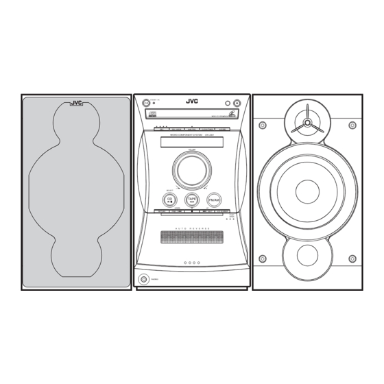
COMPACT COMPONENT SYSTEM
STANDBY/ON
1
2
3
DISPLAY
4
5
6
CLOCK
/TIMER
7
8
9
SLEEP
10
+10
BASS
TREBLE
PREV
UP
NEXT
SET
CANCEL
DOWN
CD
TAPE
FM/AM
AUX/MD
/
/SELECT
AUTO
CD
REV.MODE FM MODE
PRESET
RETURN
PRGM
RANDOM
REPEAT
ON
KARAOKE
SCREEN
SURROUND AHB PRO
VIDEO
MPX
PBC
INTRO
DIGITAL
ECHO
STILL
DIMMER
VOLUME
RM - SUXL46V REMOTE CONTROL
SP-UXL46V
Contents
Safety precautions
Preventing static electricity
Important for laser products
Disassembly method
Adjustment method
UX-L46V/UX-L36V
STANDBY / ON
REC
SURROUND
AHB PRO.
CLOCK/TIMER
AUX/MD
MICRO COMPONENT SYSTEM
UX-L46V
VOLUME
—
+
SELECT
CD
TAPE
FM/AM
DOWN
UP
RETURN
PREV
NEXT
VCD NUMBER
PUSH
OPEN
A U T O
R E V E R S E
PHONES
CA-UXL46V
SP-UXL46V
COMPACT
DIGITAL VIDEO
1-2
1-3
1-4
1-5
1-21
COPYRIGHT
2002 VICTOR COMPANY OF JAPAN, LTD.
STANDBY/ON
1
2
3
4
5
6
DISPLAY
CLOCK
7
8
9
/TIMER
10
+10
SLEEP
UP
BASS
TREBLE
PREV
NEXT
SET
DOWN
CANCEL
/
CD
TAPE
FM/AM
AUX/MD
AUTO
CD
REV.MODE FM MODE
PRESET
RETURN
PRGM
RANDOM
REPEAT
ON
KARAOKE
SCREEN
AHB PRO
VIDEO
PBC
MPX
INTRO
DIGITAL
ECHO
STILL
DIMMER
—
VOLUME
RM-SUXL36V REMOTE CONTROL
SP-UXL36V
UX-L46V/UX-L36V
US ------------------ Singapore
UN ----------------------- Asean
UX ---------------- Saudi Arabia
UF ------------------------- China
Flow of functional operation
until TOC read (CD)
Maintenance of laser pickup
Replacement of laser pickup
Description of major ICs
UX-L46V/UX-L36V
UX-L46V/UX-L36V
STANDBY / ON
REC
REV. MODE
AHB PRO.
CLOCK/TIMER
AUX/MD
MICRO COMPONENT SYSTEM
UX-L36V
VOLUME
—
+
SELECT
CD
TAPE
FM/AM
DOWN
UP
RETURN
PREV
NEXT
VCD NUMBER
PUSH
OPEN
A U T O
R E V E R S E
PHONES
CA-UXL36V
SP-UXL36V
Area Suffix
1-25
1-26
1-26
1-27~46
No.21143
Sep. 2002
1-1
Advertisement
Table of Contents

Related Manuals for JVC UX-L46V


Summary of Contents for JVC UX-L46V
- Page 1 UX-L46V/UX-L36V UX-L46V/UX-L36V SERVICE MANUAL COMPACT COMPONENT SYSTEM UX-L46V/UX-L36V STANDBY / ON STANDBY / ON REV. MODE AHB PRO. CLOCK/TIMER AUX/MD MICRO COMPONENT SYSTEM UX-L36V SURROUND AHB PRO. CLOCK/TIMER AUX/MD MICRO COMPONENT SYSTEM UX-L46V VOLUME VOLUME — SELECT — SELECT TAPE...
- Page 2 UX-L46V/UX-L36V 1. This design of this product contains special hardware and many circuits and components specially for safety purposes. For continued protection, no changes should be made to the original design unless authorized in writing by the manufacturer. Replacement parts must be identical to those used in the original circuits. Services should be performed by qualified personnel only.
-
Page 3: Preventing Static Electricity
UX-L46V/UX-L36V Preventing static electricity 1.Grounding to prevent damage by static electricity Electrostatic discharge (ESD), which occurs when static electricity stored in the body, fabric, etc. is discharged, can destroy the laser diode in the traverse unit (optical pickup). Take care to prevent this when performing repairs. -
Page 4: Important For Laser Products
UX-L46V/UX-L36V Important for laser products 5.CAUTION : If safety switches malfunction, the laser is able 1.CLASS 1 LASER PRODUCT to function. 2.DANGER : Invisible laser radiation when open and inter 6.CAUTION : Use of controls, adjustments or performance of lock failed or defeated. Avoid direct exposure to beam. -
Page 5: Disassembly Method
UX-L46V/UX-L36V Disassembly method <Main body> Removing the Metal cover (See Fig.1~4) Pull out the microphone volume knob on the rear top of the body. Remove the six screws A on the back of the main body. Remove the screw B on each side and remove the cover in the direction of the arrow. - Page 6 UX-L46V/UX-L36V Removing the Rear cover (See Fig.5) Remove the metal cover. Remove the two screws C retaining the rear cover. Fig.5 Removing the Rear panel (See Fig.6,7) Remove the metal cover and the rear cover. Remove the twelve screws D retaining the rear panel.
- Page 7 UX-L46V/UX-L36V Removing the Tuner board (See Fig.8) Remove the metal cover. Disconnect the card wire from connector CN1 on the tuner board. Remove the two screws F on the rear side and the screw G on the side. Tuner board Fig.8...
- Page 8 UX-L46V/UX-L36V Removing the Main board/ the Heat sink CD-R/RW mechanism assembly Optical digital board board (See Fig.11~13) CN905 CN902 CN904 CN903 Remove the metal cover, the rear cover and the rear panel. Disconnect the card wire from connector CN902, CN903, CN904 and CN905 on the main board and remove the CD-R/RW mechanism assembly.
- Page 9 UX-L46V/UX-L36V Removing Power transformer assembly (See Fig.15) Remove the metal cover, the rear cover, the rear panel, the CD-R/RW mechanism assembly and the main board. Disconnect the power cord from connector J1000 on the power transformer assembly. Remove the four screws K.
- Page 10 UX-L46V/UX-L36V Removing the Front panel assembly Front panel (See Fig.16~19) assembly Remove the metal cover. Remove the screw L on each side. Pull the joint h on both sides and lift the front panel assembly to release the joint g .
- Page 11 UX-L46V/UX-L36V Removing the Phones board (See Fig.20) Prior to performing the following procedure, remove the metal cover and the front panel assembly. Disconnect connector CN913 on the main board. CN913 Main board Phones board Fig.20 Removing the Cassette mechanism assembly (See Fig.21)
-
Page 12: Cassette Mechanism Section
UX-L46V/UX-L36V <Cassette Mechanism Section> Cassette mechanism Removing the Recording, Playback / Erasing Head (Refer to Figs. 1 to 3.) 1. Shifting the trigger arm seen in the right side of the head mount in the arrow-marked direction, turn the flywheel (R) counterclockwise until the head mount clicks while moving frontwards. - Page 13 UX-L46V/UX-L36V Head amp. & mechanism Removing the Head Amplifier & Mechanism control P.C. board Control P.C. Board (Refer to Figs. 4 and 5.) Belt 1. Disconnect the flexible wire from the connector CN31 on the head amplifier & mechanism control CN32 P.C.
- Page 14 UX-L46V/UX-L36V Removing the Flywheel (Refer to Figs. 8 Flywheel (R) Flywheel (L) and 9.) Remove the head amplifier & mechanism control P.C. board. Remove the main motor assembly. 1. Remove the slit washers c and d that fasten the Capstan...
- Page 15 UX-L46V/UX-L36V <CD mechanism assembly section> Video board CN101 Removing the video board (See Fig.1, 2) Remove the four screws A attaching the video board cover on the bottom of the CD mechanism assembly. Disconnect the card wire from connector CN101 on the video board.
- Page 16 UX-L46V/UX-L36V Removing the CD servo board (See Fig.3~5) Video board assembly CAUTION: Solder the shorting round before disconnecting the card wire extending from the pickup. If you do not follow this instruction, the pickup Joint a may be damaged. CN101...
- Page 17 UX-L46V/UX-L36V Removing the clamper base / tray Joint b Fitting Joint b (See Fig.6~8) Bring up the fitting in the direction of the arrow to release the three joints b. On the front side of the body, move the cam plate lever to the center.
- Page 18 UX-L46V/UX-L36V Removing the CD mechanism assembly (See Fig.9,10) CD mechanism assembly Prior to performing the following procedure, remove damper damper the clamper base / tray and the CD servo board. Remove the screw E attaching the CD mechanism assembly. Move the CD mechanism assembly backward to release the two joints c of the CD base on the front side.
- Page 19 UX-L46V/UX-L36V Removing the loading motor / loading motor board (See Fig.11, 12) Loading motor Prior to performing the following procedure, remove the clamper base / tray and the CD servo board. From upside of the loading base, remove the belt from the motor pulley.
- Page 20 UX-L46V/UX-L36V Removing the C.D. gear (1), (2) and (3) CD base (See Fig.13~16) Prior to performing the following procedure, remove the CD servo board. Remove the two screws G attaching the CD base on the bottom of the loading base.
-
Page 21: Adjustment Method
UX-L46V/UX-L36V Adjustment method Measurement Instruments Required for Tuner section Adjustment FM tuning range: 87.5MHz 108.00MHz 1. Low frequency oscillator AM tuning range: This oscillator should have a capacity to output At 9kHz intervals: 531kHz 1,710kHz 0dBs to 600 at an oscillation frequency of... - Page 22 UX-L46V/UX-L36V << >> Arrangement of Adjusting Position Cassette mechanism section Cassette mechanism section (Back side) Head azimuth Head azimuth adjusting screw adjusting screw (Forward side) (Reverse side) Head azimuth Head azimuth Playback/Recording & adjusting screw adjusting screw eraser head (Forward side)
- Page 23 UX-L46V/UX-L36V Tape Recorder Section Measurement Adjusting Standard Items Measurement method conditions positions Values Adjust the head Confirmation Test tape 1 Playback the test tape VT703L (8kHz) Maximum azimuth screw of head angle : VT703L (8kHz) 2 With the recording & playback mechanism,...
- Page 24 UX-L46V/UX-L36V Electrical Performance Adjusting Measurement Standard Items Measurement method positions conditions Values VR31 AC-225 Adjustment of Mode: Forward or 1 With the recording and playback : 4.20 recording bias reverse mode mechanism, load the test tapes (AC-514 to AC-514 current...
- Page 25 UX-L46V/UX-L36V Flow of functional operation until TOC read (CD) Check Point Slider turns REST Power Key Power ON Check that the voltage at the pin4 SW ON. of CN601 is 0V (a moment)? Automatic tuning of TE offset Check that the voltage at the...
-
Page 26: Maintenance Of Laser Pickup
UX-L46V/UX-L36V Maintenance of laser pickup Replacement of laser pickup (1) Cleaning the pick up lens Befor you replace the pick up, please try to Turn off the power switch and,disconnect the clean the lens with a alcohol soaked cotton power cord from the ac outlet. -
Page 27: Description Of Major Ics
UX-L46V/UX-L36V Description of major ICs LC75345M-X (IC901) : E.volume 1. Pin layout 36 35 34 33 32 31 30 29 28 27 26 25 24 23 22 21 20 19 2. Block diagram LINP LINM LVref LOPOUT CONTROL CIRCUIT LOGIC... - Page 28 UX-L46V/UX-L36V ES3883F (IC104) : VCD companion chip 1.Pin function 2.Blockdiagram CD-ROM Controller Remote Interrupt Remote CD ROM Control Control receiver Audio DAC Speakers Vista ES3880 (Video CD) Television NTSC/PAL Video Echo/Surround/Vocal Assist Preamp Mic 1 Volume Control Preamp DRAM Mic 2...
- Page 29 UX-L46V/UX-L36V ES3883F(2/2) Name Function Number Transmit audio data input. TBCK Transmit audio bit clock. Dual-purpose pin RWS is the audio frame sync. SEL_PLL1 Pins SEL_PLL[1.0] select the PLL clock frequency for the DCLK output. SEL_PLL1 SEL_PLL0 DCLK Bypass PLL(input mode) 27 MHz(output mode) 32.4 MHz(output mode)
- Page 30 UX-L46V/UX-L36V LA6541-X (IC801) : Servo driver 1. Pin Layout & block diagram Vref Vin4 Vin3 Level B T L B T L Level RESET shift driver driver shift Level B T L B T L Level Regulator shift driver driver...
- Page 31 UX-L46V/UX-L36V LB1641 (IC802) : DC motor driver 1. Pin layout GND OUT1 P1 IN2 VCC1 VCC2 P2 OUT2 2. Pin function Input Output Mode OUT1 OUT2 Brake CLOCKWISE COUNTER-CLOCKWISE Brake AT27C020-70JCU3 (IC102) : OTP EPROM 2MBIT 1.Terminal layout 2.Pin function Pin No.
- Page 32 UX-L46V/UX-L36V AN7317 (IC32) : ALC & Pre amplifier Pre-in Pre-NF Pre-out Rec-in Rec-out Rec-Mute R.R. 112k Mute R.R. AN7317 A L C 112k Pre-in Pre-NF Pre-out Rec-in Rec-out Low-cut Time Pin No. Pin Descriptions Channel 1 Playback Amplifier Input Channel 1 Playback Amplifier Negative Freedback...
- Page 33 UX-L46V/UX-L36V AN22000A-W (IC601) : RF head amp. 1. Pin layout 9 10 11 12 13 14 15 16 2. Block diagram 3TOUT NRFDET FEOUT TEOUT TEBPF VDET VREF 3. Pin function Pin No. Function Pin No. Function APC amp input terminal.
- Page 34 UX-L46V/UX-L36V TDA7294 (IC940, IC941) : Audio amp. 1. Pin layout -Us (POWER) +Us (POWER) N.C. N.C. MUTE STAND-BY -Us (SIGNAL) +Us (SIGNAL) BOOTSTRAP N.C. NON INUERTING INPUT INVERTING INPUT STAND-BY GND 2. Block diagram BOOTSTRAP BOOTSTRAP OUTPUT BIPOLAR MOS GHAIN &...
- Page 35 UX-L46V/UX-L36V MN662748RPMFA (IC651) : DSP 1. Terminal layout 80~61 21~40 2. Pin function Symbol Function Symbol Function 1 BCLK Not use 41 PLLF2 Not use 2 LRCK Not use 42 TOFS Not use 3 SRDATA Not use 43 WVEL Not use...
- Page 36 UX-L46V/UX-L36V MN101C30AEF (IC851) : CD micon 1. Pin layout 2. Pin Function Pin No. Symbol Function Pin No. Symbol I/O Function CONNECT TO GND DSADAT CONNECT TO GND DSAACK CONNECT TO GND CONNECT TO GND CONNECT TO GND CONNECT TO GND...
- Page 37 UX-L46V/UX-L36V MN101C38CER (IC931) : Micro controller 1. Pin layout 51 ~ 75 25 ~ 1 2. Pin Function Pin No. Symbol Function Pin No. Symbol I/O Function /CDMRST LCD BIAS GROUND CD micon reset COM3 /KARAOKE LCD BIAS GROUND Karaoke Function...
- Page 38 UX-L46V/UX-L36V BA3837 (IC902) : MIC mixer 1. Block diagram ROUT LOGIC LOUT BIAS 2. Pin function Symbol Description Pin No. Power supply Microphone mixing input MIC IN Channel L output LOUT Non connect Non connect Channel L input Signal bias...
- Page 39 UX-L46V/UX-L36V BU9253AS (IC602) : LPF & Echo mix. 1. Pin layout & block diagram MUTE ECHO VR BIAS ADINT IN DAINT IN ADINT OUT DAINT OUT ADLPF OUT DALPF IN ADLPF IN DALPF OUT MIX IN MIX OUT 2. Pin function Descriptions Pin No.
- Page 40 UX-L46V/UX-L36V GLT44016-35J4-X (IC103) : Dram 1. Pin layout 3. Pin function Pin Name Function Address inpits Row address strobe UCAS Columu address strobe / upperbyte control LCAS Columu address strobe / lower byte control Write enable Output enable LCAS Dara inputs / outputs...
-
Page 41: Block Diagram
UX-L46V/UX-L36V ES3880FL (IC101) : MPEG decoder 1. Terminal layout 2. Block diagram 80 ~ 51 Processor RAS# Interface DA[9:0] LA[17:0] DRAM Interface DBUS[15:0] LD[7:0] DRAM Huffman DOE# LCS3#, LCS#[1:0] Decoder DWE# LWR# 2Kx32 ROM RISC CAS# LOE# Processor 512x32 SRAM... - Page 42 UX-L46V/UX-L36V LA1838 (IC1) : FM AM IF amp & detector, FM MPX decoder 1. Block Diagram DECODER RF.AMP ANIT-BIRDIE MUTE BUFF STEREO P-DET AM IF PILOT 384KHz COMP S-METER AM/FM S-CLRVE S-METER IF-BUFF TUNING STEREO DRIVE DRIVE FM IF 2. Pin Function...
- Page 43 UX-L46V/UX-L36V LC72136N (IC2) : PLL frequency synthesizer 1. Pin layout FM/AM LPFOUT LPFIN CLOCK FM/ST/VCO FMIN AM/FM AMIN IFCONT SDIN IFIN 2. Block diagram Phase Reference Detector Driver Charge Pump Swallow Counter Swallow Counter 1/16,1/17 4bit 1/16,1/17 4bit Unlock Detector...
- Page 44 UX-L46V/UX-L36V L4909 (IC942) : Regulator 1. Pin layout 9 10 11 12 13 14 15 2. Block diagram VINA THERMAL REFERENCE VINB 3,13 REF+20% SHUTDOWN GENERATOR REG1 REG1 ENABLE REG2 CONTROL REG3 REG2 OVER CURRENT CHECK TRIG REG3 3. Pin functions Pin No.
- Page 45 UX-L46V/UX-L36V RT9161 / A-27CG-X (IC105) : Regulator 1. Pin layout 2. Block diagram VOUT Error Amp 1.2V VOUT Reference (TAB) 3. Pin function Pin Name Function VOUT Output Voltage Ground Power Input BU4094BCF-X (IC33) : Shift / Store registor 1. Pin layout 2.
- Page 46 UX-L46V/UX-L36V GP1UM261XK (IC750) : Detecting unit for remote control 1.Block diagram Comp- Integrator arator Demodulator Limiter B.P.F Vout TC7S08F-W (IC106) : Buffer 1. Pin layout 2. Block diagram IN B IN A OUT X TC7W08FU-X (IC107) : Nand gate 1. Pin layout & Block diagram 2.
- Page 47 UX-L46V/UX-L36V < M E M O > 1-47...
- Page 48 UX-L46V/UX-L36V UX-L46V/UX-L36V VICTOR COMPANY OF JAPAN, LIMITED AUDIO & COMUNICATION BUSINESS DIVISION PERSONAL & MOBILE NETWORK BUSINESS UNIT. 10-1,1chome,Ohwatari-machi,Maebashi-city,371-8543,Japan Printed in Japan 1-48 (No.21143) 200209...
-
Page 49: Schematic Diagrams
UX-L46V/UX-L36V SCHEMATIC DIAGRAMS COMPACT COMPONENT SYSTEM UX-L46V/UX-L36V CD-ROM No.SML200209 STANDBY / ON STANDBY / ON REV. MODE AHB PRO. CLOCK/TIMER AUX/MD MICRO COMPONENT SYSTEM UX-L36V SURROUND AHB PRO. CLOCK/TIMER AUX/MD MICRO COMPONENT SYSTEM UX-L46V VOLUME VOLUME — SELECT — SELECT... - Page 50 In regard with component parts appearing on the silk-screen printed side (parts side) of the PWB diagrams, the parts that are printed over with black such as the resistor ( diode ( ) and ICP ( ) or identified by the " " mark nearby are critical for safety. (This regulation does not correspond to J and C version.)
- Page 51 UX-L46V/UX-L36V Block diagram FMA-006 IFOUT FMC-033-1 FMH-036-4 FMH-036-3 IC901 OSCOUT MUTE/IFOUT LOUT MATRIX REMOCON FM RF MATRIX TUL,TUR FM/AM ROUT FM/AM FMDET SQIN KEY1 FMH-036-1 KEYD COM0-3, ST/MONO AM DET ONLY FOR S0-S34 AMOSC AMRF TUDATA B/E/EN/EV FW750 CN731 CN732...
- Page 52 UX-L46V/UX-L36V UX-L46V/UX-L36V Standard schematic diagrams LCD / System control / Users key control section QGF1016F3-19 CN903 QQR0621-001Z K2550 R7511 R7503 R7504 R7505 R7506 R7507 R7508 R7509 1.2K 1.8K 2.2K 2.7K 3.9K C2561 0.01 0.001 C7145 C2562 C7506 2SC2785/FE/-T QUM026-11DGZ4 Q7031 FW750 0.01...
- Page 53 UX-L46V/UX-L36V Audio / Source selector section QGA2501C1-02 CN908 CN915 CN916 CN917 QGB2510J1-10 QGB2510J1-11 QGD2504C1-03Z R2880 D2810 W2000 R2301 C2119 R2300 R2881 D2811 0.27 W2000 R2802 22/16 Q3000 C2117 QSK0109-001 KTA1267/YG/-T KTC3199/GL/-T C2215 RY901 22/16 Q2800 1K( 1/4W) 150K R2147 L2800 R2801 0.012...
- Page 54 UX-L46V/UX-L36V UX-L46V/UX-L36V Power board section IC940 IC941 TDA7294 TDA7294 D4219 R4000 C4004 R4001 C4005 DZ6.8BSB-T2 22/50 22/50 C4204 C4002 C4203 10/50 100/16 D4221 R4012 R4010 R4011 R4013 C4018 C4013 DZ11BSB-T2 10/50 1.2K 10/50 1.2K C4202 C4010 C4011 R4203 R4204 1.2K 5.1K...
- Page 55 UX-L46V/UX-L36V CD servo section R862 R863 R856 REST DSASTB DRMUTE 2.2K R864 R865 CloseSW OpenSW R867 R866 OPEN R868 P.ON R869 CLOSE BLKCK R857 R858 uDSAACK IC851 STAT R859 uDSADAT MN101C30A MDATA R860 uDSASTB MCLK /P.ON R861 CDMRST J902 R885...
- Page 56 UX-L46V/UX-L36V UX-L46V/UX-L36V Tape control section 1SR139-400-T2 SG-105F3-BB,C C211 R212 2.2K 0.0015 C208 R208 R211 C204 R203 R202 5.6K 4.7/25 0.033 2.4K 1.8K R204 1.2K MSI-5U2LWA QGB2011L1-10 IC31 BA3126N R304 FW31 CN32 QGB2011M1-10 VWS304-06A13K R301 IC32 AN7317 LV42902-001A R207 R371 R107 R104 1.2K...
- Page 57 UX-L46V/UX-L36V Tuner section 0.0039 0.47/50 0.0022 470P 0.047 22/16 0.27 1/50 0.047 22/16 0.001 10/16 10/16 100/10 1000P 0.0015 0.0015 3.3K VCF2L3B-105Z LC72136N LA1838 QNB0014-001 VCF2L3B-105Z 5.6K DTA114YKA-X 150P QQR0793-001 150P 150P 1/50 1.2K 0.022 QQR0796-002 0.047 QAX0610-001Z 100/10 3.3k 4.7K...
- Page 58 UX-L46V/UX-L36V UX-L46V/UX-L36V Primary section FW950 CN951 QUM153-16DGZ4 QGD2504C1-03Z FW950 CN951 QUM153-16DGZ4 QGD2504C1-03Z T1000 QQT0375-003 S1000 QSW0812-001 T1000 QQT0375-003 F1002 R1004 D1012 R1003 4.7K 1SS119-041-T2 R1004 D1012 R1003 4.7K 1SS119-041-T2 Q1002 C1012 F1000 KTC3199/GL/-T 4.7/25 F1000 Q1002 C1012 KTC3199/GL/-T 4.7/25 J1000...
- Page 59 UX-L46V/UX-L36V Video control section LA17 IC102 LA16 LA15 LA12 R118 D102 R119 L101 3.3U DGND C113 Q101 D101 X101 C111 C112 C115 R120 QAX0700-001Z 470p 470p C114 L102 R121 3.3u 100k 1000p K101 C131 C130 0.1/16 100/10 K102 VGND VDD3...
- Page 60 UX-L46V/UX-L36V UX-L46V/UX-L36V Mic section R6020 C6016 4.7/50 1.5K C6015 0.01 R6022 QQR0779-001Z R6019 K6003 K6002 QQR0779-001Z IC611 BA15218 C6010 C6012 100P IC612 BU9253AS R6007 C6002 1/50 R6032 C6003 0.1/50 R6017 C6023 7.5K 2.2/50 C6008 C6020 C6004 1/50 3300P R6010 C6009 2.2/50...
- Page 61 UX-L46V/UX-L36V Printed circuit boards Main board J900 C2755 [B2083] K2500 C2564 C2000 C2705 CN902 CN904 CN903 C2556 C2563 R7062 R2222 J901 [B2090] K2550 C2565 L2900 R2224 D7012 C2555 C2561 K2551 Q6003 R7127 [B2089] R3221 R7064 C2562 [B2082] K7001 R6034 R3220...
- Page 62 UX-L46V/UX-L36V UX-L46V/UX-L36V Front board D7503 D4002 S7506 S7500 R4001 C4005 D7502 IC750 R4003 R4013 C4035 R4027 C4011 C7507 C4041 R4011 R4027 C7502 R4023 C4019 D4004 C4009 C7501 R4016 R4044 B7501 C4034 R7511 S7502 D4003 S7505 S7504 S7503 S7501 C4021 B7502...
- Page 63 UX-L46V/UX-L36V CD board (Forward side) (Reverse side) [B683] CN651 C683 CN652 C682 CN606 CN801 C690 R820 R690 W605 R819 C832 B717 B726 B825 C831 B611 R831 B752 C673 D831 C679 B727 B655 C815 R806 B821 IC802 B719 R805 IC601 R808...
- Page 64 UX-L46V/UX-L36V UX-L46V/UX-L36V Video board Tuner board (Forward side) CN102 IC105 C112 CN101 SIDE.A L101 R105 C111 K101 C115 C113 C131 C104 D101 IC101 X101 C117 R101 C105 C103 C114 R128 D102 R121 R132 R130 R135 C118 R136 C129 C121 IC104...
- Page 65 UX-L46V/UX-L36V Head amplifier board Cassette switch board 2-15...
- Page 66 UX-L46V/UX-L36V VICTOR COMPANY OF JAPAN, LIMITED AUDIO & COMUNICATION BISINESS DIVISION PERSONAL & MOBILE NETWORK BUSINESS UNIT. 10-1,1Chome,Ohwatari-machi,maebashi-city,371-8543,Japan Printed in Japan No.21143SCH 200209...
-
Page 67: Table Of Contents
UX-L46V/UX-L36V PARTS LIST [ UX-L46V/UX-L36V ] * All printed circuit boards and its assemblies are not available as service parts. Area suffix US ---------------------- Singapore UN --------------------------- Asean UX ------------------ Saudi Arabia UF ---------------------------- China - Contents - 3- 3 Exploded view of general assembly and parts list (Block No.M1) - Page 68 UX-L46V/UX-L36V < M E M O >...
- Page 69 UX-L46V/UX-L36V Exploded view of general assembly and parts list Block No. Input board Tuner board board Volume board Video board Power trans board Heat sink board Control board 26 34...
- Page 70 1 TUNER/C.BASE QYSDSF2610Z QYSDSF2610Z TAPPING SCREW 7 F.PANEL/PWB GV40122-003A SPACER GV30264-002A FUNC.BTTN.ASSY GV30270-001A LCD HOLDER GV30265-002A CONTROL BTN.A 1 UX-L46V GV40280-001A LCD LENS(A) GV30265-001A CONTROL BTN.A 1 UX-L36V GV40281-002A LCD LENS (B) GV30266-003A CONTROL BTN.B 1 UX-L36V GV40282-001A LCD SHEET GV30266-004A CONTROL BTN.B...
- Page 71 1 FC732 QUQ110-1609AJ FFC WIRE 1 FC601 QJJ010-060801 SIN CR C-C WIRE 1 W 801 POWER TRANSF 1 T1000 QQT0375-003 GV30349-001A SPACER 1 UX-L46V GV40170-003A SPACER 1 FOR C2200 GV40322-001A PROTECT SHEET A US,UN,UX QYSBSF3012E SPECIAL SCREW 2 R.PNL/VOL.SEL US,UN,UX VYSA1R3-003...
-
Page 72: Cd Loading Base Assembly And Parts List (Block No.md)
UX-L46V/UX-L36V CD loading base assembly and parts list Block No. LOAD-JEM-2M Grease = G-474C = EBS0006-009B FIG A Apply grease to groove and support convex. FIG A Dimension gap for motor pulley... - Page 73 UX-L46V/UX-L36V Parts list (CD loading base) Block No. MDMM Item Description Parts number Parts name Q'ty Area VYH1238-001 LODING BASE MMN-6F1LB8K MOTOR QGF1201F3-05 CONNECTOR 1 CN505 QSW0472-001 SWITCH 1 S851 QYSPSPT2640Z MINI SCREW E75984-221SS C.D M.PULLEY E75950-002 BELT E75985-221SS C.D GEAR (1) C.D GEAR (2)
-
Page 74: Cassette Mechanism Assembly And Parts List (Block No.mp)
UX-L46V/UX-L36V Cassette mechanism assembly and parts list Block No. SLC-S102M Grease = EM-30L =UD-24 =UD-24H2 =LEN-320M =JC-888B =MOBIL-1 The lower side Switch board Head amplifier board... - Page 75 UX-L46V/UX-L36V Parts list (Cassette machanism) Block No. MPMM Item Parts number Parts name Q'ty Description Area VKS1165-00J CHASSIS B.ASS'Y VKS2274-002 REEL GEAR VKW5286-002 B.T. SPRING VKS5559-001 PLAY IDLE GEAR VKS5595-002 BLIND VKS5560-003 FR IDLE GEAR LV42013-001A EARTH SPRING SLC-RP3SVM HEAD MOUNT ASSY VKY3149-002 CASSETTE SP.
- Page 76 UX-L46V/UX-L36V Electrical parts list (Input board) Block No. 01 Item Parts number Parts name Remarks Area Item Parts number Parts name Remarks Area CN270 QGB2510K2-10 CONNECTOR VOCAL BRD C2554 QDGB1HK-102Y C CAPACITOR CN900 QGF1201C3-10 CONNECTOR C2555 QDGB1HK-102Y C CAPACITOR CN901...
- Page 77 UX-L46V/UX-L36V Electrical parts list (Input board) Block No. 01 Item Parts number Parts name Remarks Area Item Parts number Parts name Remarks Area C7005 QDYB1CM-103Y C CAPACITOR K6002 QQR0621-001Z FERRITE BEADS C7008 QETN0JM-228Z E CAPACITOR 2200MF 20% 6.3V K6003 QQR0621-001Z...
- Page 78 UX-L46V/UX-L36V Electrical parts list (Input board) Block No. 01 Item Parts number Parts name Remarks Area Item Parts number Parts name Remarks Area R2039 QRE141J-103Y C RESISTOR 10K 5% 1/4W R2924 QRJ146J-101X UNF C RESISTOR 100 5% 1/4W R2040 QRE141J-471Y...
- Page 79 UX-L46V/UX-L36V Electrical parts list (Input board) Block No. 01 Item Remarks Parts number Parts name Area R7110 QRE141J-103Y C RESISTOR 10K 5% 1/4W R7111 QRE141J-222Y C RESISTOR 2.2K 5% 1/4W R7112 QRE141J-222Y C RESISTOR 2.2K 5% 1/4W R7113 QRE141J-103Y C RESISTOR...
- Page 80 UX-L46V/UX-L36V Electrical parts list (Main board) Block No. 02 Item Parts number Parts name Remarks Area Item Parts number Parts name Remarks Area CN731 QGF1201F3-23 CONNECTOR D1000 1N4003S-T5 SI DIODE CN732 QGF1201F3-23 CONNECTOR D1001 1N4003S-T5 SI DIODE CN905 QGA2501F1-03 CONNECTOR...
- Page 81 UX-L46V/UX-L36V Electrical parts list (Main board) Block No. 02 Item Parts number Parts name Remarks Area Item Parts number Parts name Remarks Area R4001 QRE141J-102Y C RESISTOR 1.0K 5% 1/4W R7506 QRE141J-182Y C RESISTOR 1.8K 5% 1/4W R4002 QRE141J-472Y C RESISTOR 4.7K 5% 1/4W...
-
Page 82: Electrical Parts List (Block No.01~07)
UX-L46V/UX-L36V Electrical parts list (CD board) Block No. 03 Item Parts number Parts name Remarks Area Item Parts number Parts name Remarks Area C 600 NCB31EK-104X C CAPACITOR D 601 1SS355-X DIODE C 601 NCB31HK-222X C CAPACITOR D 602 1SS355-X... - Page 83 UX-L46V/UX-L36V Electrical parts list (CD board) Block No. 03 Item Remarks Parts number Parts name Area R 819 QRE141J-2R2Y C RESISTOR 2.2 5% 1/4W R 820 QRE141J-2R2Y C RESISTOR 2.2 5% 1/4W R 822 NRSA63J-473X MG RESISTOR R 831 QRE141J-100Y...
- Page 84 UX-L46V/UX-L36V Electrical parts list (Tuner board) Block No. 04 Item Parts number Parts name Remarks Area Item Parts number Parts name Remarks Area NCB21HK-223X C CAPACITOR 2SC2814/4-5/-X TRANSISTOR NCB21HK-103X C CAPACITOR KRA107S-X TRANSISTOR EETC1CM-106ZJC E CAPACITOR QRE141J-560Y C RESISTOR 56 5% 1/4W...
- Page 85 UX-L46V/UX-L36V Electrical parts list (Head amplifier board) Block No. 05 Item Parts number Parts name Remarks Area Item Parts number Parts name Remarks Area C 101 NCS21HJ-821X C CAPACITOR R 106 NRSA63J-332X MG RESISTOR C 102 NCS21HJ-221X C CAPACITOR R 107...
- Page 86 UX-L46V/UX-L36V Electrical parts list (Video board) Block No. 07 Item Remarks Parts number Parts name Area Item Parts number Parts name Remarks Area C 101 NCF31CZ-104X C CAPACITOR R 120 NRSA63J-750X MG RESISTOR C 102 NCF31CZ-104X C CAPACITOR R 121...
- Page 87 UX-L46V/UX-L36V < M E M O > 3-21...
-
Page 88: Packing Materials And Accessories Parts List (Block No.m3,M5)
UX-L46V/UX-L36V Packing materials and accessories parts list Block No. Block No. A1~A8, A11~A13 A9, A10 A9, A10 3-22... - Page 89 1 UX-L46V GV20187-001A CARTON ASSY 1 UX-L36V US,UN,UX GV20187-002A CARTON ASSY 1 UX-L36V GV10116-001A TOP CUSHION 1 UPPER SIDE UX-L46V GV10107-001A TOP CUSHION 1 UPPER SIDE UX-L36V GV10117-001A BOTTOM CUSHION 1 BOTTOM SIDE UX-L46V GV10108-001A BOTTOM CUSHION 1 BOTTOM SIDE UX-L36V...