
Related Manuals for Notifier AFP-200


Summary of Contents for Notifier AFP-200
- Page 1 Analog Fire Panel AFP-200 Installation Manual Document 15511 10/14/2002 Rev: 15511:H2 ECN 02-436 Technical Manuals Online! - http://www.tech-man.com...
- Page 2 (especially in bedrooms), smoking in bed, and violent explosions (caused by escaping gas, improper storage of flammable materials, etc.). Precau-L-4-2002.fm AFP-200 PN 15511:H2 10/14/2002 Technical Manuals Online! - http://www.tech-man.com...
-
Page 3: Installation Precautions
Acclimate Plus™, HARSH™, NOTI•FIRE•NET™, ONYX™, and VeriFire™ are trademarks, and FlashScan® and VIEW® are registered trademarks of NOTIFIER. NION™ and UniNet™ are trademarks of NIS. NIS™ and Notifier Integrated Systems™ are trademarks and NOTIFIER® is a registered trademark of Fire•Lite Alarms, Inc. Echelon® is a registered trademark and LonWorks™ is a trademark of Echelon Corporation. ARCNET® is a registered trademark of Datapoint Corporation. -
Page 4: Table Of Contents
1.11.4 Notification Appliance and Releasing Circuits (TB2) ...................27 1.11.5 Relays (TB3) ..............................28 1.11.6 24 VDC Power (TB1) ............................28 1.12 Cabinet Dimensions ..........................28 1.12.1 Surface Mount with a BB-17 Battery Box .....................28 AFP-200 PN 15511:H2 10/14/2002 Technical Manuals Online! - http://www.tech-man.com... - Page 5 3.2.6 Key Programming Terms ..........................68 3.2.7 How to Avoid Programming Errors .........................69 3.3 Program Change Options........................70 3.3.1 Overview ................................70 3.4 How to Enter Program Change ......................71 3.4.1 Program Change Map ............................72 AFP-200 PN 15511:H2 10/14/2002 Technical Manuals Online! - http://www.tech-man.com...
-
Page 6: Technical Manuals Online! - Http://Www.tech-Man.com
4.8.7 Style 6 Operation ............................118 4.9 Read Status ............................118 4.9.1 Overview ................................118 4.9.2 How to Enter Read Status ..........................119 4.9.3 Read Status Options ............................119 4.9.4 Read Point ..............................119 4.9.5 Using the History Buffer ..........................124 AFP-200 PN 15511:H2 10/14/2002 Technical Manuals Online! - http://www.tech-man.com... - Page 7 Specific Requirements ............................132 Additional Requirements ............................132 B.2 Central Station Fire Alarm Systems (Protected Premises) ............133 Installing a Notifier 911AC ............................133 Installing a UDACT ..............................134 B.3 NFPA 72 Auxiliary Fire Alarm System.................... 135 B.4 Wiring a Remote Station Fire Alarm System .................. 136 Overview .................................136...
- Page 8 Clear the Verification Counter ..........................175 Clear the Entire History Buffer ..........................175 Set the Pre-Alarm for Alert or Action Level ......................176 CRT-2 Configuration ..............................176 Appendix J Expansion Power Supplies............177 J.1 Overview .............................. 177 AFP-200 PN 15511:H2 10/14/2002 Technical Manuals Online! - http://www.tech-man.com...
- Page 9 N.3 Mounting the CHG-120 ........................191 Mounting the Charger into a CAB-X3 Series Cabinet ...................191 Mounting the Charger into a Battery Box ......................192 N.4 Connecting the CHG-120 ........................194 Connecting a CHG-120 to the AFP-200 .........................194 AFP-200 PN 15511:H2 10/14/2002 Technical Manuals Online! - http://www.tech-man.com...
-
Page 10: About This Manual
Appendix L “U.S. Coast Guard & Lloyd’s Register” provides a list of equipment suitable for use in marine and shipyard applications as compatible with this control panel. AFP-200 PN 15511:H2 10/14/2002 Technical Manuals Online! - http://www.tech-man.com... - Page 11 Auxiliary Power Supply APS-6R AVPS-24 AVPS-24/AVPS-24E Control module FCM-1 AFP-200 circuit board CRT-2 LCD display 80-character LCD (liquid crystal display) Monitor Module FMM-1 or FMM-101 PRN-5 Relay module FRM-1 Table 2 General Terms AFP-200 PN 15511:H2 10/14/2002 Technical Manuals Online! - http://www.tech-man.com...
- Page 12 DN-3783 System Connections AFP-200 Basic System Drawing 51265 Compatible Devices Device Compatibility Document 15378 Off-line programming and installation Veri•Fire Medium Systems CD: AFP-200 Upload/Download Utility Verifire-CD Networking applications NAM-232 Network Adaptor Module Manual 50038 Networking applications Noti•Fire•Net Manual 50257 Noti•Fire•Net Manual, Network Version 4.0 & Higher...
- Page 13 NEC Article 760 Fire Alarm Systems • Applicable Local and State Building Codes • Requirements of the Local Authority Having Jurisdiction • Notifier Device Compatibility Document • ADA Americans with Disabilities Act AFP-200 PN 15511:H2 10/14/2002 Technical Manuals Online! - http://www.tech-man.com...
-
Page 14: Section 1 System Overview
Section 1 System Overview 1.1 General Description The AFP-200 is a compact, cost-effective, intelligent fire alarm control panel with an extensive list of powerful features. The power supply and all electronics are contained on a single circuit board, providing a complete fire control system for most applications. -
Page 15: Components
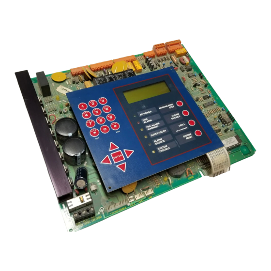
EIA-232 terminal PRN printer CRT terminal To other FACP Figure 1 AFP-200 System Features 1.3 Components 1.3.1 Membrane Switch Panel Figure 2 shows the membrane switch panel which includes the following: • Windows for the Liquid Crystal Display (LCD) and six system status indicator LEDs. -
Page 16: Panel Sounder
The control panel includes three dry contact relays for system alarm, system trouble, and supervisory. Contacts are rated 2 A at 30 VDC and 0.5 A at 30 VAC (resistive). For installation instructions, “Standard Relays (TB3)” on page 36. AFP-200 PN 15511:H2 10/14/2002 Technical Manuals Online! - http://www.tech-man.com... -
Page 17: Main Assemblies
System Overview Main Assemblies 1.4 Main Assemblies The AFP-200 main assemblies include the CPU board, the cabinet for enclosing the control panel, the transformer assembly, and the batteries. 1.4.1 CPU Board The control panel circuit board contains the system’s central processing unit (CPU), power supply, and other primary components. -
Page 18: Cabinet
1.4.6 Batteries The cabinet provides space for 7 AH or 12 AH batteries (for 18 AH batteries use the BB-17 battery box). Batteries must be ordered separately. AFP-200 PN 15511:H2 10/14/2002 Technical Manuals Online! - http://www.tech-man.com... -
Page 19: Optional Devices & Option Modules
FACP can contain as many as 96 input/output points, or SIZE SWITCH SETTINGS NO OF POINTS TENS as few as eight points. Refer to the NIB-96 Network ONES Interface Board manual for further information and installation instructions. AFP-200 PN 15511:H2 10/14/2002 Technical Manuals Online! - http://www.tech-man.com... -
Page 20: Field Charger/Power Supply - Fcps-24
A single assembly containing both meters mounts in the lower-left corner of the AFP-200 cabinet as shown in Figure 3 on page 17. AFP-200 PN 15511:H2 10/14/2002... -
Page 21: Trim Ring
FSP-751. Same as FSI-751, but uses a FSI-751, FSP-751 photoelectric sensing chamber. The FSP-751T adds thermal sensors that will alarm at a fixed temperature of 135° F. Designed to provide open area protection. AFP-200 PN 15511:H2 10/14/2002 Technical Manuals Online! - http://www.tech-man.com... -
Page 22: Addressable Modules
NFPA Style Y or Style Z. Comes with a TENS TENS thermoplastic cover for mounting to a 4-inch (10.16 cm) square ONES ONES LOOP LOOP ADDRESS ADDRESS mounting box. FCM-1 AFP-200 PN 15511:H2 10/14/2002 Technical Manuals Online! - http://www.tech-man.com... - Page 23 LOOP ADDRESS FRM-1 XP5-C Modules. XP5-C Modules allow the AFP-200 to control a maximum of five individual circuits. These modules can be configured as NACs/telephone or relay circuits. Their function is similar to that of the control or relay modules described above.
-
Page 24: End-Of-Line Devices
System Overview End-of-Line Devices 1.8 End-of-Line Devices 1.8.1 Overview Table 4 contains a list of the end-of-line devices that you can install in an AFP-200 system: Option Description Notes A2143-00 A 47K End-Of-Line Resistor (ELR) Assembly Supplied with monitor, control... -
Page 25: Annunciator Control System (Acs)
AFM-32A – The AFM-32A contains 32 red alarm LEDs, a system trouble LED, an ON LINE/POWER LED, and a local panel sounder with a silence/acknowledge switch. The AFM-32A is fixed at address 1, and will not accept expander modules. AFP-200 PN 15511:H2 10/14/2002 Technical Manuals Online! - http://www.tech-man.com... -
Page 26: Peripheral Devices (Tb4)
(alarm, trouble) and status changes within the system. • Time-stamps the printout with the current time-of-day and date. Note: Time stamping is a function of the AFP-200 panel. 1.10.3 Keltron Remote Printer (Model VS4095) The VS4095 is a two-color (red and black), 40-column, 24 VDC printer that can print up to 50 messages in 90 seconds. -
Page 27: Specifications
1.11 Specifications This section contains electrical specifications for the control panel. 1.11.1 Primary AC Power (TB7) Primary AC connections are made through TB7 on the AFP-200. Wire size: minimum 14 AWG with 600 VAC insulation. • AFP-200. 120 VAC, 50/60 Hz, 3.0 A •... -
Page 28: Relays (Tb3)
(40.64 cm) Depth = 4.75" (12.065 cm) Battery Box = 8.25" (20.955 cm) (Optional BB-17) Battery Box = 14.5" (36.83 cm) (Optional BB-17) Figure 6 AFP-200 Cabinet and BB-17 Battery Box Dimensions AFP-200 PN 15511:H2 10/14/2002 Technical Manuals Online! - http://www.tech-man.com... -
Page 29: Semi-Flush Mount
System Overview Cabinet Dimensions 1.12.2 Semi-flush Mount Figure 7 shows dimensions for semi-flush mounting of the AFP-200 cabinet using a TR-4XG Trim Ring. Trim Ring = 17.62" 1.5" (3.8 cm) typical (44.7548 cm) for 4" (10.16 cm) wall Trim Ring = 19.12"... -
Page 30: Section 2 Installation
In addition, installers should be familiar with the following standards: • NEC Article 300 Wiring Methods. • NEC Article 760 Fire Protective Signaling Systems. • Applicable Local and State Building Codes. • Requirements of the Local Authority Having Jurisdiction. AFP-200 PN 15511:H2 10/14/2002 Technical Manuals Online! - http://www.tech-man.com... -
Page 31: Installation Checklist
CAUTION: Make sure to install system components in the precise order in the checklist. Failure to do so can damage the control panel and other system components Table 6 contains an installation checklist for installing, wiring, and testing an AFP-200 system: Task Refer to Mount the cabinet backbox to the wall. -
Page 32: Backbox Mounting
Using upper keyholes, mount the backbox over the two screws. Tighten the screws. Install and tighten the lower two screws. When location is dry and free of construction dust, reinstall the CPU board. AFP-200 PN 15511:H2 10/14/2002 Technical Manuals Online! - http://www.tech-man.com... -
Page 33: Ac And Dc Power Connections
2.4.1 AC Power Connections (TB7) Primary power required for the AFP-200 is 120 VAC, 50/60 Hz, 3 A and primary power required for the AFP-200E is 220/240 VAC, 50/60 Hz, 1.5 A. Overcurrent protection for this circuit must comply with Article 760 of the National Electrical Code (NEC) and/or local codes. -
Page 34: Battery Power Connection (J3)
• the Audio/Visual Power Supply (AVPS-24); or • the Auxiliary Power Supply (APS-6R). For detailed information, including installation instructions, refer to Appendix J “Expansion Power Supplies”. AFP-200 PN 15511:H2 10/14/2002 Technical Manuals Online! - http://www.tech-man.com... -
Page 35: Dc Output Power Connections (Tb1)
5.0 A. An additional 3.0 A are available when using an expansion power supply (AVPS-24/AVPS-24E or APS-6R). For details on expansion power supplies, refer to Appendix J “Expansion Power Supplies”. AFP-200 PN 15511:H2 10/14/2002 Technical Manuals Online! - http://www.tech-man.com... -
Page 36: Standard Relays (Tb3)
2.0 A @ 30 VDC (resistive). The control panel also provides a Form-A supervisory contact rated for 2.0 A @ 30 VDC (resistive). Form-C contacts Form-A contact Figure 13 Relay Connections (TB3) AFP-200 PN 15511:H2 10/14/2002 Technical Manuals Online! - http://www.tech-man.com... -
Page 37: Devices - Remote Printers And Crts (Tb4)
Remote printers require 120 VAC, 50/60 Hz primary power. A secondary power source (battery backup) is not provided. The use of a separate uninterruptable power supply (UPS), UL-listed for Fire Protective Signaling is recommended. AFP-200 PN 15511:H2 10/14/2002 Technical Manuals Online! - http://www.tech-man.com... -
Page 38: Keltron Printer
DC IN - 24VDC (14 AWG) Figure 15 Keltron Printer Connections Notes on Figure 15: Outputs are power-limited, but are not supervised. Connections must be made with overall foil/braided-shield twisted paired cable AFP-200 PN 15511:H2 10/14/2002 Technical Manuals Online! - http://www.tech-man.com... -
Page 39: Crt Connections
OUT OUT IN Connect TX (Pin 3) to TB4 terminal 1 Connect REF (Pin 7) to TB4 terminal 2 Connect RX (Pin 2) to TB4 terminal 3 Figure 16 CRT Connections AFP-200 PN 15511:H2 10/14/2002 Technical Manuals Online! - http://www.tech-man.com... - Page 40 To AUX Port of CRT To EIA Port of CRT with keyboard 3 2 1 To EIA Port of next CRT or PRN Figure 17 Connections For Multiple CRTs or Combined CRTs and Printers AFP-200 PN 15511:H2 10/14/2002 Technical Manuals Online! - http://www.tech-man.com...
-
Page 41: Wiring A Signaling Line Circuit (Slc)
“SLC Wiring with an Intelligent Detector” on page 59 Detector Wiring an Addressable “SLC Wiring with an NBG-12LX Addressable Manual Pull Station” Manual Pull Station on page 60 Table 9 SLC Wiring Topics AFP-200 PN 15511:H2 10/14/2002 Technical Manuals Online! - http://www.tech-man.com... -
Page 42: Slc Devices
• Style 6, 7. 10,000 ft. (3048 m) (12 AWG) total twisted-pair. 2.9.3 Control Panel Capacity AFP-200 capacity includes up to 99 intelligent detectors and an additional combination Refer to the installation drawings supplied with each of up to 99 addressable pull stations, and monitor, control and relay modules. In... -
Page 43: Slc Performance
Do not let the shield drain wire or the shield SLC + foil touch the system cabinet. SLC - Figure 20 Shield Termination – Full Conduit AFP-200 PN 15511:H2 10/14/2002 Technical Manuals Online! - http://www.tech-man.com... -
Page 44: Setting An Slc Address For A Module
Breakaway Tab - Devices come with a raised breakaway tab on the TENS rotary switch. This tab must be left intact for this system. ONES Figure 22 Setting SLC Address on Module AFP-200 PN 15511:H2 10/14/2002 Technical Manuals Online! - http://www.tech-man.com... -
Page 45: Wire Requirements For A Two-Wire Slc
+ (Branch E) =10,000 feet (3048 m) or less (12 AWG) Branch D Loop Out Branch A no connection Figure 24 Measuring the Total Length of Wire in a Two-wire SLC AFP-200 PN 15511:H2 10/14/2002 Technical Manuals Online! - http://www.tech-man.com... -
Page 46: Wire Requirements For A Four-Wire Slc
Figure 26 identifies the output and return loops from SLC terminal TB5 on the CPU: SLC A (loop return) T-Tapping is not allowed on a four-wire SLC. SLC B (output loop) no connection Figure 26 Measuring the Wire Length – Four-wire SLC AFP-200 PN 15511:H2 10/14/2002 Technical Manuals Online! - http://www.tech-man.com... - Page 47 Loop Isolator Module Loop Isolator Module no connection Connect (+) to TB 6-3 Connect (–) to TB 6-5 TX REF RX REF OUT OUT IN Figure 27 Two-wire SLC (Style 4) AFP-200 PN 15511:H2 10/14/2002 Technical Manuals Online! - http://www.tech-man.com...
- Page 48 Connect SLC Out to TB 6-3 (+) and TB 6-5 (–). TX REF RX REF OUT OUT IN Connect SLC Return to TB 6-4 (+) and 6-6 (–). Figure 28 Typical Four-wire SLC Circuit (Style 6) AFP-200 PN 15511:H2 10/14/2002 Technical Manuals Online! - http://www.tech-man.com...
-
Page 49: Four-Wire Slc Overview
SLC segment or branch. Refer to 2.9.6 “Setting an SLC Address for a Module” for instructions on addressing the modules. AFP-200 PN 15511:H2 10/14/2002 Technical Manuals Online! - http://www.tech-man.com... -
Page 50: Wiring An Idc With Monitor Modules
FZM-1. The FZM-1 Monitor Module is an addressable module used to monitor a single Initiating Device Circuit of smoke detectors. Use FZM-1 modules to monitor conventional, two-wire smoke detectors. The FZM-1 requires an AFP-200 PN 15511:H2 10/14/2002 Technical Manuals Online! - http://www.tech-man.com... - Page 51 • Security Service. Maximum IDC wiring resistance is 20 ohms. Note: Refer to Installation Document shipped with each two-wire detector monitor module for specific installation notes for this variety of module. AFP-200 PN 15511:H2 10/14/2002 Technical Manuals Online! - http://www.tech-man.com...
- Page 52 24 VDC four-wire detector resettable power: SLC (+) TB6-3 24 VDC (+) TB1-5 SLC (–) TB6-5 24 VDC (–) TB1-6 Figure 34 Typical Style B (Class B) IDC Wiring with FMM-1 Modules AFP-200 PN 15511:H2 10/14/2002 Technical Manuals Online! - http://www.tech-man.com...
- Page 53 24 VDC filtered, regulated and resettable power: SLC out 24 VDC (+) TB1-5 SLC (+) TB 6-3 24 VDC (–) TB1-6 SLC (–) TB 6-5 Figure 35 Typical Style B (Class B) IDC Wiring with FZM-1 AFP-200 PN 15511:H2 10/14/2002 Technical Manuals Online! - http://www.tech-man.com...
- Page 54 24 VDC filtered, low-noise and resettable power: SLC (+) to TB6-3 24 VDC (+) to TB1-5 SLC (–) to TB6-5 24 VDC (–) to TB1-6 Figure 36 Typical Style D (Class A) IDC Wiring with FMM-1 AFP-200 PN 15511:H2 10/14/2002 Technical Manuals Online! - http://www.tech-man.com...
- Page 55 SLC out: 24 VDC (+) to TB1-5 SLC (+) to TB6-3 24 VDC (–) to TB1-6 SLC (–) to TB6-5 Figure 37 Typical Style D (Class A) IDC Wiring with FZM-1 Modules AFP-200 PN 15511:H2 10/14/2002 Technical Manuals Online! - http://www.tech-man.com...
-
Page 56: Wiring A Notification Appliance Circuit (Nac) Or Control Circuit
Ratings for the dry contacts on a Form-C relay module are: Resistive: 3.0 A @ 30 VDC max Non-coded application Further rating information is available in the module document and data sheet. AFP-200 PN 15511:H2 10/14/2002 Technical Manuals Online! - http://www.tech-man.com... -
Page 57: Slc Wiring With Control Modules
Connect 24 VDC power (Figure 40). Set the control module rotary switches to the required SLC address. (The control module takes one module address on the SLC.) Refer to 2.9.6 “Setting an SLC AFP-200 PN 15511:H2 10/14/2002 Technical Manuals Online! - http://www.tech-man.com... - Page 58 24 VDC filtered, regulated, nonresettable SLC out 24 VDC (+) to TB1-1 SLC (+) to TB6-3 24 VDC (–) to TB1-2 SLC (–) to TB6-5 Figure 40 Typical Wiring for an NFPA Style Y NAC AFP-200 PN 15511:H2 10/14/2002 Technical Manuals Online! - http://www.tech-man.com...
-
Page 59: Slc Wiring With An Intelligent Detector
If using an RA400Z Remote LED Annunciator: (a) connect the RA400Z positive terminal to base terminal 3; and (b) connect the RA400Z negative terminal to base terminal 1. AFP-200 PN 15511:H2 10/14/2002 Technical Manuals Online! - http://www.tech-man.com... -
Page 60: Slc Wiring With An Nbg-12Lx Addressable Manual Pull Station
44). Factory preset is address 00. Record the device address and SLC number on the label inside the pull station. Note: In the sample shown below, the switches are set to address 12. AFP-200 PN 15511:H2 10/14/2002 Technical Manuals Online! - http://www.tech-man.com... -
Page 61: Option Module Installation
Transmitter Module and the RTM-8 Relay Module. To enable module supervision, you must cut jumper JP5 before installing an option module. Figure 44 shows the location of the connectors and jumper J5. Jumper JP5 Afp2incab Figure 44 Optional Module Location AFP-200 PN 15511:H2 10/14/2002 Technical Manuals Online! - http://www.tech-man.com... -
Page 62: Installing A 4Xtm Module
TBL jumper (shown in Figure 45) Figure 45 shows 4XTM module components with polarities shown in activated positions. Polarities are shown in activated positions. Figure 45 4XTM Module Connections and Components AFP-200 PN 15511:H2 10/14/2002 Technical Manuals Online! - http://www.tech-man.com... -
Page 63: Installing An Rtm-8 Module
6. Secure the upper right corner of the RTM-8 with the (remaining) long metal standoff. 7. Using the screw removed from the AFP-200 CPU and the screw supplied with the RTM-8, secure the module to the CPU at the points indicated. - Page 64 Zone Relay Contact Ratings – 6 A @ 30 VDC or 300 VAC. Material: Silver Nickel. Refer to the power-limited label located on the AFP-200 cabinet door. Make a notation on the label for each circuit used as a nonpower-limited circuit. (Refer to the example on the label).
-
Page 65: Section 3 Programming
Overview Section 3 Programming 3.1 Overview The AFP-200 is an intelligent, field-programmable Fire Alarm Control Panel. Field-programming the control panel lets you customize the fire alarm system by selecting and setting program options for addressable SLC devices (intelligent detectors, monitor modules, relay modules, and control modules), NACs, and Panel Circuits. -
Page 66: Getting Started
Figure 50 Sample Incorrect Password Screen From the Incorrect Password screen (Figure 50), press the key and enter the BACKSPACE correct Program Change or Status Change password or contact the manufacturer for assistance. AFP-200 PN 15511:H2 10/14/2002 Technical Manuals Online! - http://www.tech-man.com... -
Page 67: How To Use The Programming Keypad
4. Press three times, then press 5. Press three times, then press 6. Press two times, then press 7. Press , then press then press Table 13 Entering Alphanumeric Characters AFP-200 PN 15511:H2 10/14/2002 Technical Manuals Online! - http://www.tech-man.com... -
Page 68: Programming Shortcuts
A missing device is a detector or module removed from the SLC (TB6) that exists in the current program. Monitor module An addressable monitor module that monitors conventional alarm-initiating devices. AFP-200 PN 15511:H2 10/14/2002 Technical Manuals Online! - http://www.tech-man.com... -
Page 69: How To Avoid Programming Errors
Time Control (Z95, Z96) • Do not program a time control function (Z95, Z96) as a releasing function. • Do not program a heat detector to a time control zone (Z95, Z96). AFP-200 PN 15511:H2 10/14/2002 Technical Manuals Online! - http://www.tech-man.com... -
Page 70: Program Change Options
Change system “How to Edit System Functions (7=sys)” on page 89 functions Check the program for “How to Check the Program (8=check)” on page 92 errors Table 15 Program Change Topics AFP-200 PN 15511:H2 10/14/2002 Technical Manuals Online! - http://www.tech-man.com... -
Page 71: How To Enter Program Change
Select a Program Change option by pressing the numeric key (0-8) that matches The System Trouble LED remains flashing throughout the option. To exit Program Change and return to the Program Entry screen, press all Program Change key. BACKSPACE operations. AFP-200 PN 15511:H2 10/14/2002 Technical Manuals Online! - http://www.tech-man.com... -
Page 72: Program Change Map
For details, refer to “How to Check Check the new or PROGRAM CHECK OK. the Program (8=check)” on page 92 current program for RE-TEST PANEL NOW errors 05:31P MON 11/03/97 Figure 54 Map of Program Change Options AFP-200 PN 15511:H2 10/14/2002 Technical Manuals Online! - http://www.tech-man.com... -
Page 73: How To Clear A Program From Memory (0=Clr)
A program exists in memory and “How to Change Autoprogram you want to view system System Defaults” on page 77 settings assigned during autoprogram, such as custom labels, passwords, and so on. Table 16 Autoprogram Functions AFP-200 PN 15511:H2 10/14/2002 Technical Manuals Online! - http://www.tech-man.com... - Page 74 To edit this information, refer to “How to Edit or (detector at SLC Delete a Point (2=point)” on page 78 for address 01 shown) instructions. Figure 57 Sample New Device Screen AFP-200 PN 15511:H2 10/14/2002 Technical Manuals Online! - http://www.tech-man.com...
- Page 75 SLC. When finished identifying SLC devices, the control panel displays information for the new detector at SLC address 04 on the LCD display as shown in Figure 59. AFP-200 PN 15511:H2 10/14/2002 Technical Manuals Online! - http://www.tech-man.com...
- Page 76 SLC. Figure 61 Sample Missing Device Screen Press the key to delete detector 04 from the program and return to the ENTER Program Change screen (Figure 53 on page 71). AFP-200 PN 15511:H2 10/14/2002 Technical Manuals Online! - http://www.tech-man.com...
- Page 77 (3=passwd)” on page 85 All Systems Normal Custom Custom message label = 40 blanks “How to Change a System Message Message (4=message)” on page 86 Table 18 Default Parameters for System Functions AFP-200 PN 15511:H2 10/14/2002 Technical Manuals Online! - http://www.tech-man.com...
-
Page 78: How To Edit Or Delete A Point (2=Point)
From the Program Change screen (Figure 53 on page 71), press the 2 key (Point) to display the Point Programming Entry screen (Figure 64). POINT@PROG.ENTER: 1 = MODIFY POINT 2 = DELETE POINT Figure 63 Point Programming Screen AFP-200 PN 15511:H2 10/14/2002 Technical Manuals Online! - http://www.tech-man.com... - Page 79 • Press the Up arrow key to display the point at the previous address or press the Down arrow key to select the point at the next address. • You cannot delete a panel circuit. Table 20 How to Display a Point AFP-200 PN 15511:H2 10/14/2002 Technical Manuals Online! - http://www.tech-man.com...
- Page 80 A Type Code defines the function of the detector. Table 21 contains a list of detector Type Codes: Type Code Detector Type SMOKE (ION) Ionization smoke detector (FSI-751) SMOKE (PHOTO) Intelligent smoke detector (FSP-751) HEAT (ANALOG) Intelligent thermal detector (FST-751) Table 21 Detector Type Codes AFP-200 PN 15511:H2 10/14/2002 Technical Manuals Online! - http://www.tech-man.com...
- Page 81 01 through 19 20 through 39 40 through 59 60 through 79 80 through 99 Table 22 Monitor Module Default Zone Selection AFP-200 PN 15511:H2 10/14/2002 Technical Manuals Online! - http://www.tech-man.com...
- Page 82 Short = Trouble (Refer to Section 3 latching TROUBLE “Programming” & Section 4 “Operation”). Causes Security Alarm on open or short latching BURGLAR ALA (Refer to Appendix E “Combination Fire/Burglary Applications.”) Table 23 Monitor Module Type Codes AFP-200 PN 15511:H2 10/14/2002 Technical Manuals Online! - http://www.tech-man.com...
- Page 83 Short = Trouble (supervised and power-limited, see Appendix D) REL CKT ULC Contacts operated upon release RELEASE FORM Note: A releasing circuit is always non-silenceable. Table 24 Control or Relay Module Type Codes AFP-200 PN 15511:H2 10/14/2002 Technical Manuals Online! - http://www.tech-man.com...
- Page 84 Selecting option 2 from the Point Programming screen (Figure 63) lets you choose a detector or module point to delete. Figure 69 shows the Delete Point Selection screen and contains instructions for accessing a point. AFP-200 PN 15511:H2 10/14/2002 Technical Manuals Online! - http://www.tech-man.com...
-
Page 85: How To Change A Programming Password (3=Passwd)
Follow the instructions in Figure 71. To return to the Program Change screen without changing the password, press the left cursor (backspace) key. When finished changing the password, press the key to return to the Program ENTER Change screen. AFP-200 PN 15511:H2 10/14/2002 Technical Manuals Online! - http://www.tech-man.com... -
Page 86: How To Change A System Message (4=Message)
LCD display returns to the Change Zone Label screen. If the zone is out of range, the software ignores the key. To return to the ENTER Program Change screen, press the key. BACKSPACE AFP-200 PN 15511:H2 10/14/2002 Technical Manuals Online! - http://www.tech-man.com... -
Page 87: How To Edit A Special Zone (6=Spl Zones)
F0. The System Alarm relay, the 4XTM Polarity Reversal Alarm Output, and the 4XTM Municipal Box Output delay if PAS is selected, but do not delay for Presignal operations. AFP-200 PN 15511:H2 10/14/2002 Technical Manuals Online! - http://www.tech-man.com... - Page 88 Special Zone Change screen (Figure 74), key in 97 to display the Holiday Change screen. Figure 78 shows a typical Holiday Change screen: PRG@HOLIDAY@ZONE 97 01/01@@04/10@@05/26 07/04@@09/07@@11/26 11/27@@12/24@@12/25 Figure 78 Holiday Change Screen AFP-200 PN 15511:H2 10/14/2002 Technical Manuals Online! - http://www.tech-man.com...
-
Page 89: How To Edit System Functions (7=Sys)
Silence switch function when a fire alarm occurs. You can enter a timer value between 0-300 seconds or enter 000 for no timer. The timer starts at the first alarm and restarts with each new alarm. AFP-200 PN 15511:H2 10/14/2002 Technical Manuals Online! - http://www.tech-man.com... - Page 90 EIA-232 port (TB4) on the control panel. For detailed information configuring the control panel with a computer or terminal, refer to Appendix I “Terminal Interface Protocol”. Table 28 lists the operating mode selections. AFP-200 PN 15511:H2 10/14/2002 Technical Manuals Online! - http://www.tech-man.com...
- Page 91 N, press the Up or Down key. press the Up or Down key. ST=4 To switch the value between ST=4 and ST=6, press the Up or Down key. Figure 82 Editing System Functions AFP-200 PN 15511:H2 10/14/2002 Technical Manuals Online! - http://www.tech-man.com...
-
Page 92: How To Check The Program (8=Check)
“How to Set the System Time and Date (5=time)” on page 98 Walk test the system “How to do a Walk Test (6=walk test)” on page 99 Table 29 Status Change Topics AFP-200 PN 15511:H2 10/14/2002 Technical Manuals Online! - http://www.tech-man.com... -
Page 93: Entering Status Change
Status Change operations (except for Walk Test) have a two-minute timer. (The Walk Test feature has a 1-hour timer.) If no keys are pressed for two minutes, the control panel exits Status Change and returns to normal operation. AFP-200 PN 15511:H2 10/14/2002 Technical Manuals Online! - http://www.tech-man.com... -
Page 94: Status Change Programming Map
For details, refer to “How to do a Walk test the system. Press WALK@TEST@PRESS Test (6=walk test)” on page 99 ENTER@TO@START key to BACKSPACE BACKSPACE@TO@STOP stop. Figure 85 Map of Status Change Programming Options AFP-200 PN 15511:H2 10/14/2002 Technical Manuals Online! - http://www.tech-man.com... -
Page 95: How To Disable Or Enable A Point (1=Disable)
When finished selecting Enable/Disable selections, press the key to BACKSPACE return to the Status Change screen (Figure 84 on page 93). AFP-200 PN 15511:H2 10/14/2002 Technical Manuals Online! - http://www.tech-man.com... -
Page 96: How To Set Detector Selections (2=Sens/Comp)
From the Status Change screen (Figure 84 on page 93), press the 2 key to display the Detector Sensitivity/Comp screen (Figure 88). Status Change DET.@SENS/COMP Password ENTER@POINTS:@AA,E Figure 88 Detector Sensitivity/Comp Screen AFP-200 PN 15511:H2 10/14/2002 Technical Manuals Online! - http://www.tech-man.com... -
Page 97: How To Clear Alarm Verification Counters (3=Clr Ver)
Figure 90 Verification Count Clear Screen Press the key to clear the verification counters or press the ENTER BACKSPACE to return to the Status Change screen (Figure 84) without clearing the verification AFP-200 PN 15511:H2 10/14/2002 Technical Manuals Online! - http://www.tech-man.com... -
Page 98: How To Clear The History Buffer (4=Clr Hist)
When finished entering the time and date, press the key to change the time ENTER and date in system memory and return to the Status Change screen. AFP-200 PN 15511:H2 10/14/2002 Technical Manuals Online! - http://www.tech-man.com... -
Page 99: How To Do A Walk Test (6=Walk Test)
History buffer. • Turns on the System Trouble LED and the System Trouble relay. If a new trouble occurs, all control modules programmed for Walk Test activate for 8 seconds and AFP-200 PN 15511:H2 10/14/2002 Technical Manuals Online! - http://www.tech-man.com... - Page 100 Exit Walk Test immediately and return the system to normal operation. • Notify the building owner/operator, fire department, and other persons that testing is complete and the system is operating normally. AFP-200 PN 15511:H2 10/14/2002 Technical Manuals Online! - http://www.tech-man.com...
-
Page 101: Section 4 Operation
How to Operate a Panel with a Non-Alarm Condition How to Operate the Panel with an Output Circuit Trouble Control-By-Event Control-By-Event Operation Operation Releasing Releasing Functions Functions Time Functions Time Functions Read Status Read Status Table 32 Operation Topics AFP-200 PN 15511:H2 10/14/2002 Technical Manuals Online! - http://www.tech-man.com... -
Page 102: The Membrane Panel
W X Y Keypad - / . Figure 98 Programming Keypad To learn how to enter alphanumeric characters on the Programming Keypad, “How to Use the Programming Keypad” on page 67. AFP-200 PN 15511:H2 10/14/2002 Technical Manuals Online! - http://www.tech-man.com... -
Page 103: How To Use The Enter Key And Cursor Keys
The Membrane Panel (see Figure 97 on page 102) contains four Operator Keys: , and . This section ACKNOWLEDGE STEP ALARM SILENCE DRILL SYSTEM RESET provides the purpose and operation of each operator key. AFP-200 PN 15511:H2 10/14/2002 Technical Manuals Online! - http://www.tech-man.com... - Page 104 Turns on all silenceable circuits (all control modules and NAC/Panel Circuits programmed as silenceable) • Turns off the ALARM SILENCE • Sends a “Manual Evacuate” message to the LCD display, the History buffer, installed Terminal Mode LCD-80s, and installed printers AFP-200 PN 15511:H2 10/14/2002 Technical Manuals Online! - http://www.tech-man.com...
-
Page 105: How To Read System Status Led Indicators
To turn off Press the key. SYSTEM RESET Pre-Alarm Warning Function The LED indicates that a programmed Pre-Alarm ALARM WARNING level is reached. For details on Pre-Alarm, refer to Appendix G “Pre-Alarm (AWACS™) Applications”. AFP-200 PN 15511:H2 10/14/2002 Technical Manuals Online! - http://www.tech-man.com... -
Page 106: How To Operate The Control Panel
4.3 How to Operate the Control Panel This section contains instructions for operating the control panel under the following operating conditions: • Normal Operation • Fire Alarm Operation • Trouble Operation • Supervisory Operation AFP-200 PN 15511:H2 10/14/2002 Technical Manuals Online! - http://www.tech-man.com... -
Page 107: How To Operate The Panel In Normal Operation
“All Systems Normal” message to the LCD display, LCD-80, History buffer, and printer. This trouble restore occurs even if the troubles were never acknowledged (auto restore). During a Trouble operation the control panel does the following: AFP-200 PN 15511:H2 10/14/2002 Technical Manuals Online! - http://www.tech-man.com... - Page 108 STEP the current trouble for 1 minute, then begins to automatically step through events in the following order: Alarms, in order of address. Supervisory, in order of address, or security alarms. AFP-200 PN 15511:H2 10/14/2002 Technical Manuals Online! - http://www.tech-man.com...
-
Page 109: How To Operate A Panel With A Trouble Monitor Point
Label of the first zone TROUBLE ALARM:@PULL@STATION Membrne WEST@HALLWAY@FLR@5 FLR 05 MAIN BUILDING 11:13A 12/15/97 Device activated Time and date the device activated Figure 104 Sample Display for an Fire Alarm AFP-200 PN 15511:H2 10/14/2002 Technical Manuals Online! - http://www.tech-man.com... -
Page 110: How To Operate A Panel With A Supervisory Condition
LED will operate the same as a supervisory, but the LCD display will show the security type code. Refer to Appendix E for further information on security alarms. AFP-200 PN 15511:H2 10/14/2002 Technical Manuals Online! - http://www.tech-man.com... -
Page 111: How To Operate A Panel With A Non-Alarm Condition
Addresses (last three digits in LCD field) are B01, B02, B03 or B04. • The default Type Code field is BELL CIRCUIT • They may be used for March Time, California Code, Temporal, and Two Stage coded functions. AFP-200 PN 15511:H2 10/14/2002 Technical Manuals Online! - http://www.tech-man.com... -
Page 112: How The Control Panel Indicates A Panel Circuit Trouble
Input – Detector at NAC/Panel Circuit SLC address 12 B04 listing software listing Z04 in its zone Z04 in its CBE. CBE. Software Zone – Zone 04 Figure 108 CBE Example AFP-200 PN 15511:H2 10/14/2002 Technical Manuals Online! - http://www.tech-man.com... -
Page 113: Releasing Functions
(91-94) activate. At least one smoke detector and at least one heat detector, all mapped to one of the four releasing zones (91-94) activate. Table 36 Cross Zoning Types AFP-200 PN 15511:H2 10/14/2002 Technical Manuals Online! - http://www.tech-man.com... -
Page 114: Releasing Functions
A hazard is protected by assigning one of the four zones to each initiating device, abort switch, manual release switch, and release solenoid. Refer to Appendix D for detailed information about releasing applications. AFP-200 PN 15511:H2 10/14/2002 Technical Manuals Online! - http://www.tech-man.com... -
Page 115: Intelligent Detector Functions
Alert level programmed for 50% of that, or 0.50% per foot (30.48 cm) . The 50% is a real-time display and may change. Alert Pre-Alarms automatically restore. Figure 110 Typical Display for a Pre-Alarm Alert Event AFP-200 PN 15511:H2 10/14/2002 Technical Manuals Online! - http://www.tech-man.com... -
Page 116: Time Functions
When the current date matches any of 8th day in programming ZONES 95 the nine holiday dates, the control panel and 96. activates ZONE 97. Table 38 Control Time Functions AFP-200 PN 15511:H2 10/14/2002 Technical Manuals Online! - http://www.tech-man.com... -
Page 117: Coding Operation (Nac Only)
Zone 90. The System Alarm relay, the 4XTM Polarity Reversal Alarm Output, and the 4XTM Municipal Box Output delay if PAS is selected, but do not delay for Presignal operations. AFP-200 PN 15511:H2 10/14/2002 Technical Manuals Online! - http://www.tech-man.com... -
Page 118: Special System Timers
Read Status. You can enter Read Status while in Fire Alarm or Trouble mode. If a new alarm or trouble occurs during Read Status functions, the control panel automatically exits Read Status. AFP-200 PN 15511:H2 10/14/2002 Technical Manuals Online! - http://www.tech-man.com... -
Page 119: How To Enter Read Status
The sequence of points is: • Detector points 01-99 • Module points 01-99 • Panel Circuits 01-04 • System parameters • Software Zones 01-89 • Special Zones 90-99 AFP-200 PN 15511:H2 10/14/2002 Technical Manuals Online! - http://www.tech-man.com... - Page 120 Walk Test (*) is not selected by Silenceable (S) selected by default. default. (To select, change to “W”) (* = not selected). Required selection Figure 115 Module Read Status Sample Screen AFP-200 PN 15511:H2 10/14/2002 Technical Manuals Online! - http://www.tech-man.com...
- Page 121 (00 = no soak timer). programmed to this zone in alarm to activate the zone). Figure 118 Typical Display for a Releasing Control Zone AFP-200 PN 15511:H2 10/14/2002 Technical Manuals Online! - http://www.tech-man.com...
- Page 122 Figure 121 shows NAC coding of March Time. Other possible program selections are Temporal, California, and Two-stage. For more information on coding, refer to “Coding Operation (NAC only)” on page 117. AFP-200 PN 15511:H2 10/14/2002 Technical Manuals Online! - http://www.tech-man.com...
- Page 123 Style 4 or Style 6. The ST=6 setting is used for both Style 6 and Style 7 operation. • AVPS=N indicates that there is no AVPS-24/AVPS-24E or APS-6R expansion power supply installed (refer to Appendix J). AFP-200 PN 15511:H2 10/14/2002 Technical Manuals Online! - http://www.tech-man.com...
-
Page 124: Using The History Buffer
The time that the event NO DEVICES INSTALLED occurred 01:23P WED 05/22/98 PROGRAM CHANGE 1=AUTO PROGRAM 01:25P WED 05/22/98 ALL SYSTEMS NORMAL 01:27P WED 05/22/98 Figure 125 Sample Read History Display AFP-200 PN 15511:H2 10/14/2002 Technical Manuals Online! - http://www.tech-man.com... - Page 125 During all Read Status operations—except print operations—a two-minute timer starts. If no key is pressed during the two-minute timer, the LCD returns to the previous display. Each key press restarts the two-minute timer. AFP-200 PN 15511:H2 10/14/2002 Technical Manuals Online! - http://www.tech-man.com...
-
Page 126: Appendix A Power Supply Calculations
The control panel requires connection to a separate, dedicated AC branch circuit (120 VAC for AFP-200 and 220/240 VAC for AFP-200E), which must be labeled FIRE ALARM. This branch circuit must connect to the line side of the main power feed of the protected premises. -
Page 127: The Main Power Supply
Calculation Column 2 is less than 5.0 A. 5.0 A Total System 2.5 A combined 0.5 A combined 2.5 A 1.5 A Figure 127 TB1 and TB2 Alarm Current Limitations AFP-200 PN 15511:H2 10/14/2002 Technical Manuals Online! - http://www.tech-man.com... -
Page 128: Calculating The System Current Draw
Use Table 47 to calculate current draws as follows. Enter the quantity of devices in all three columns. Enter the current draw where required. Refer to the Notifier Device Compatibility Document for compatible devices and their current draw. Calculate the current draws for each in all columns. - Page 129 Calculation Column 2 and Calculation Column 3 to Table 48 on page 131. Notes for Table 47: Refer to the Notifier Device Compatibility Document for compatible devices and their current draws. For non-English language systems, the LCD-80TM (Terminal Mode) standby current is 0.100 A.
-
Page 130: Calculating The Battery Size
Alarm ampere hours. Multiply the sum by the derating factor of 1.2 to get the proper battery size (in ampere hours). Write the ampere-hour requirements on the Protected Premises label located inside AFP-200 PN 15511:H2 10/14/2002 Technical Manuals Online! - http://www.tech-man.com... -
Page 131: Selecting And Locating Batteries
If sizing battery for 4 hour standby use a derating factor of 1.5 • NFPA 12, 12A, 12B require 24 hours plus 5 minutes activation. The total ampere hours required cannot exceed 18 AH with an internal charger. AFP-200 PN 15511:H2 10/14/2002 Technical Manuals Online! - http://www.tech-man.com... -
Page 132: Appendix B Nfpa Applications
NFPA standard are listed below. • AFP-200 control panel containing the main circuit board, cabinet (backbox and door), main supply transformer and power supply. • Batteries (refer to Appendix A for standby power requirements). -
Page 133: Central Station Fire Alarm Systems (Protected Premises)
B.2 Central Station Fire Alarm Systems (Protected Premises) B.2.1 Installing a Notifier 911AC The Notifier 911AC for connection to a Central Station Receiver or Protected Premises Receiving Unit must be installed as shown in Figure 129. For additional information on the 911AC, refer to Document 74-06200-005. The 911AC communicator comes in a separate cabinet. -
Page 134: Installing A Udact
1 (+) and terminal 2 (–)] with correct polarity (Figure 130)? Is the UDACT ACS/TERM switch set to the ACS (left) position (Figure 130)? Is the UDACT Start Monitor Address set to 1 and is the Stop Monitor Address set AFP-200 PN 15511:H2 10/14/2002 Technical Manuals Online! - http://www.tech-man.com... -
Page 135: Nfpa 72 Auxiliary Fire Alarm System
Jumper JP2 must be in the LE MUNCPL BOX position for use in this application Municipal Box Circuit Polarities shown in alarm condition Figure 131 Wiring a Municipal Box Connected to a RTM-8 AFP-200 PN 15511:H2 10/14/2002 Technical Manuals Online! - http://www.tech-man.com... -
Page 136: Wiring A Remote Station Fire Alarm System
Note: For remote station fire alarm systems, cut Jumper JP5 on the control panel CPU board. For additional information on the RS-82 Remote Station Receiver Unit, refer to the Fire•Lite Alarms, Inc. RS-82 Instruction Manual. AFP-200 PN 15511:H2 10/14/2002 Technical Manuals Online! - http://www.tech-man.com... -
Page 137: Using A 4Xtm Module
Input 4 Alarm Signal Input 5 Alarm Signal Input 6 Alarm Signal Input 7 Alarm Signal Input 8 Alarm Signal Input 9 RS82to4XTM.cdr Figure 133 NFPA 72 Remote Station Fire Alarm System AFP-200 PN 15511:H2 10/14/2002 Technical Manuals Online! - http://www.tech-man.com... -
Page 138: Using An Rtm-8 Module
Up to ten AFP-200 Protected Premises Units may be monitored by one AM2020/AFP1010 Receiving Unit using ten SLC loops and ten NIB-96 modules. • Disable the ground fault circuit on the AFP-200 by cutting jumper JP9 because the AFP-200 PN 15511:H2 10/14/2002 Technical Manuals Online! - http://www.tech-man.com... - Page 139 If connecting an RPT-485W isolating repeater module between the AM2020/AFP1010 and the control panel, a common connection between the two panels is not needed. However—a system common connection must be made from the AFP-200 to RPT-485W, and the AFP-200 ground fault jumper JP9 should not be cut. •...
-
Page 140: Appendix C Annunciators
Appendix C Annunciators C.1 LCD-80 Display The LCD-80 alphanumeric display module is an AFP-200 ancillary device that provides two modes of operation: Terminal Mode, where the LCD-80 acts as a display repeater; and ACS Mode, where the LCD-80 acts as an alphanumeric annunciator. To select the operation mode, use switch SW2 on the CPU (Figure 3 on page 17). -
Page 141: Acs Annunciation Interface (Tb5 On Cpu)
Table 53 contains the data formats for annunciator address 2. Note the following: The National Standard of Canada (CAN/ULC-5527) requires a dedicated display to use yellow visual indicators to show the status of supervisory inputs. Notifier annunciators intended for Canadian Supervisory Service are: ACM-16ATCS4, ACM-16ATCS, ACM-16ATY, ACM-32ACS8, ACM-32ACS, and ACM-32AY. - Page 142 Not used Input Z55 Active Z55 Trouble Not used Input Z56 Active Z56 Trouble Not used Note: 1 System Trouble excludes AC Power Fail. Table 52 Data Formats at Annunciator Address 1 AFP-200 PN 15511:H2 10/14/2002 Technical Manuals Online! - http://www.tech-man.com...
- Page 143 Not used Input Not used Not used Not used Input Not used Not used Not used Input Not used Not used Not used Table 53 Data Formats at Annunciator Address 2 AFP-200 PN 15511:H2 10/14/2002 Technical Manuals Online! - http://www.tech-man.com...
-
Page 144: Terminal Mode Eia-485 Connections (Tb5)
Connect the EIA-485 circuit as follows: Connect each LCD-80 to 24 VDC operating power (power-limited and supervised) to the AFP-200 as shown in Figure 139 on page 146. Set SW2 on the control panel to the TERM position (left position). -
Page 145: Acs Mode Eia-485 Connections
Connect the EIA-485 circuit as follows: Connect each LCD-80 to 24 VDC operating power (power-limited and supervised) to the AFP-200 as shown in Figure 139 on page 146. Set SW2 on the control panel to the “ACS” position (right position). -
Page 146: Power Connections For Lcd And Acs Series Annunciators
EIA-232 Transmit EIA-232 Reference - System Common OUT - System Common IN +24 VDC OUT +24 VDC IN EIA-232 Receive TB1-3 (+) TB1-4 (–) Figure 139 Power Connections for LCD-80 Series Annunciators AFP-200 PN 15511:H2 10/14/2002 Technical Manuals Online! - http://www.tech-man.com... -
Page 147: Acs And Ldm Series Eia-485 Connections
Connect the EIA-485 circuit as follows: Connect each annunciator to 24 VDC operating power (power-limited and supervised) to the AFP-200 as shown in Figure 139 on page 146. Set SW2 on the control panel to the “ACS” position (right position). -
Page 148: Appendix D Releasing Applications
Status banner Abort timer selection Delay timer selection (see Table 57) PRG@SOFTWARE@ZONE RELEASE@CONTROL DELAY=XX@ABORT=XXX CROSS=N@SOAK=XX@Z91 Cross Zoning selection Releasing zone (see Table 55) Soak timer selection Figure 141 Release Control Screen AFP-200 PN 15511:H2 10/14/2002 Technical Manuals Online! - http://www.tech-man.com... -
Page 149: Releasing Zone Functions
(Z91-Z94) is alarmed. Table 55 Cross Zoning Types Note: Only the first non-special zone listed in the zone map is used to determine Cross=Z. AFP-200 PN 15511:H2 10/14/2002 Technical Manuals Online! - http://www.tech-man.com... -
Page 150: Soak Timer (Nfpa 16 Applications Only)
(00=no Soak Timer) Figure 143 Soak Timer Selection Enter a value for the Soak Timer: 00=no Soak Timer; or 10-15 minutes to select the amount of time for the Soak Timer. AFP-200 PN 15511:H2 10/14/2002 Technical Manuals Online! - http://www.tech-man.com... -
Page 151: Abort Timer
Section 2 “Installation”. You can also install multiple Man. Release modules, which provide a logical “or” function, similar to multiple conventional abort switches on a single conventional zone. AFP-200 PN 15511:H2 10/14/2002 Technical Manuals Online! - http://www.tech-man.com... -
Page 152: Rel Ckt Ulc
To activate when any of the initiating devices activate: map the control module to a separate zone (not Z91, Z92, Z93, or Z94) that is also mapped to all initiating devices of the hazard. AFP-200 PN 15511:H2 10/14/2002 Technical Manuals Online! - http://www.tech-man.com... -
Page 153: Auxiliary Control Relay Functions
Connecting a releasing device to a control panel through a control module (Figure 145 on page 154) • Connecting the control panel to an agent release abort station (Figure 146 on page 155) AFP-200 PN 15511:H2 10/14/2002 Technical Manuals Online! - http://www.tech-man.com... -
Page 154: Connecting A Releasing Device To A Control Panel Through An Slc Control Or Relay Module
D.3.2 Connecting an NBG-12LRA Agent Releasing Abort Station Figure 146 shows typical connections for wiring an NBG-12LRA Agent Releasing Abort Station to the AFP-200. All wiring for releasing circuits is supervised against opens and shorts. When connecting this type of circuit, follow these instructions: For releasing applications, use an end-of-line device (part number REL-47K) with the control module. - Page 155 Releasing Applications Connecting Releasing Devices SLC loop to AFP-200 NBG-12LRA Manual Abort Yellow Black TB6-5 (-) See Document 51369 FMM-101 for installation details. Violet TB6-3 (+) Manual Release Yellow Black – – FMM-101 Violet Normal AFP-200 TB1-1 +24 VDC Release...
- Page 156 Relay Contact Push-Button Switch set for NAC AFP-200 Power Supervision 24 VDC Relay A77-716B TB1-2 (-) AFP-200 24 VDC TB1-1 (+) Figure 147 Employing NBG-12LRA Agent Release-Abort Station with XP5 Modules AFP-200 PN 15511:H2 10/14/2002 Technical Manuals Online! - http://www.tech-man.com...
-
Page 157: Appendix E Combination Fire/Burglary Applications
Wire the control panel with the STS-200 security tamper switch kit. To do so, follow these instructions: Mount the STS-200 to the cabinet (Figure 148). Run the wiring behind the CPU board (Figure 148). Cut Jumper JP3. AFP-200 PN 15511:H2 10/14/2002 Technical Manuals Online! - http://www.tech-man.com... -
Page 158: Wiring For Proprietary Security Alarm Applications
Notification Appliance Circuit. Note the following: The control module is configured as a Notification Appliance Circuit and programmed in the Protected Premises Unit. Supplementary use only applies to UL-listed systems. AFP-200 PN 15511:H2 10/14/2002 Technical Manuals Online! - http://www.tech-man.com... -
Page 159: Connecting To An Am2020/Afp1010 Receiving Unit
(refer to Section 3 “Programming”). To program a point used for security, follow these instructions: Select the address of a monitor module used for security. Set the monitor module type code to BURGLAR ALA AFP-200 PN 15511:H2 10/14/2002 Technical Manuals Online! - http://www.tech-man.com... -
Page 160: Operation
When the system is reset a 30-second exit timer starts. During this time, the tamper switch and all burglar alarm type alarms are ignored. There is no entrance delay timer. AFP-200 PN 15511:H2 10/14/2002 Technical Manuals Online! - http://www.tech-man.com... -
Page 161: Appendix F Wire Requirements
NR45-24 Remote 12 AWG in conduit • 20 ft. • 12 AWG secondary power (6.096 m) source (max) Table 59 Wiring Requirements AFP-200 PN 15511:H2 10/14/2002 Technical Manuals Online! - http://www.tech-man.com... -
Page 162: Appendix G Pre-Alarm (Awacs™) Applications
0.80 is a real-time display, updated every few seconds, to show the current reading of this detector. In this example, the reading equals 40% of alarm, which puts the control panel into Alert condition. AFP-200 PN 15511:H2 10/14/2002 Technical Manuals Online! - http://www.tech-man.com... -
Page 163: Action Level Pre-Alarm Function
You can adjust the setting of the two Action and Alert levels (from 00% to 99%) to suit your application. From the Special Zone Change screen (Figure 74 on page 87), select AFP-200 PN 15511:H2 10/14/2002 Technical Manuals Online! - http://www.tech-man.com... -
Page 164: Selecting Pre-Alarm Application Levels
Detector D13 – Set to alarm at 2.00%, D13 so it will Pre-Alarm at 1.00% per foot (30.48 cm) obscuration. • Detector D14 – Set to alarm at 1.00%, so it will Pre-Alarm at 0.50% per foot (30.48 cm) obscuration. AFP-200 PN 15511:H2 10/14/2002 Technical Manuals Online! - http://www.tech-man.com... -
Page 165: Self-Optimizing Pre-Alarm Function
Set Pre-Alarm settings: ALERT=00 and ACTION=01 as shown in Figure 156. Program each detector for which Pre-Alarm is desired. Figure 157 shows a sample screen for a detector selected for Pre-Alarm. For detailed information on point AFP-200 PN 15511:H2 10/14/2002 Technical Manuals Online! - http://www.tech-man.com... -
Page 166: Audible Warning Applications For Awacs
Alert Pre-Alarm operation. If all sounder-bases are to activate on alarm, wire the power for these bases through two relay-module relay contacts that will reverse the polarity to the sounder bases on alarm. AFP-200 PN 15511:H2 10/14/2002 Technical Manuals Online! - http://www.tech-man.com... -
Page 167: Appendix H Special Zones
Z90, the control panel delays the following outputs: • the System Alarm relay; • the 4XTM Polarity Reversal Alarm output; and • the 4XTM Municipal Box output. Note: PAS will not delay RTM-8 relay outputs. AFP-200 PN 15511:H2 10/14/2002 Technical Manuals Online! - http://www.tech-man.com... -
Page 168: Time Control
Two-stage Canada functions like standard Two-Stage except only the Manual Evacuate will cause NAC to go to second stage. If acknowledge is pressed on first stage, timer will not time out. Subsequent alarm will restart timer. AFP-200 PN 15511:H2 10/14/2002 Technical Manuals Online! - http://www.tech-man.com... -
Page 169: Appendix I Terminal Interface Protocol
Passwords: User-defined password for Alter Status functions. Requirements: The terminal must be mounted in a UL-864 listed enclosure, a Notifier Rack-51, Rack-67, or positioned to provide equivalent protection against unauthorized use. AFP-200 PN 15511:H2 10/14/2002 Technical Manuals Online! - http://www.tech-man.com... -
Page 170: Local Monitor Mode (Locm)
*Requires the user defined password for access. Table 63 LocM Functions I.2.3 Remote Terminal Mode (RemT) Functions, passwords, and special requirements of Remote Terminal Mode (RemT) are: Functions: Read Status only. See Table 64. AFP-200 PN 15511:H2 10/14/2002 Technical Manuals Online! - http://www.tech-man.com... -
Page 171: Using The Crt-2 For Read Status
Use with UL EDP-listed terminals, including personal computers with Veri•Fire™ Upload/Download software or terminal emulation software. Intended for terminals connected through modems, including Notifier TPI modems connected through a public switched telephone network. Table 64 summarizes the functions available with the RemT mode: Functions Lets you... -
Page 172: Read Point
NORMAL HEAT(ANALOG) DETECTOR ADDRESS 32 Z32 Z Z 08:10A 08/20/97 D06 NORMAL MONITOR MODULE ADDRESS 02 Z01 Z Z Z Z 08:10A 08/20/97 M02 BELL CIRCUIT PANEL CIRCUIT NO.3 Z00 Z Z Z Z 08:10A 08/20/97 M02 AFP-200 PN 15511:H2 10/14/2002 Technical Manuals Online! - http://www.tech-man.com... -
Page 173: View The History Buffer
Clear the verification counter for all the addressable detectors in the system. Clear History Clear the contents of the history buffer. Set Action/Alert Set the Pre-Alarm for the Alert or Action level. Table 66 Alter Status Functions AFP-200 PN 15511:H2 10/14/2002 Technical Manuals Online! - http://www.tech-man.com... -
Page 174: Accessing Alter Status Options
Enter the first letter to read one of the following: • Detector • Module • Bell Circuit (NAC) Enter the address or number of the device. Press <Enter> and a display similar to the following will appear. AFP-200 PN 15511:H2 10/14/2002 Technical Manuals Online! - http://www.tech-man.com... -
Page 175: Change Detector Sensitivity Levels
Press Enter to Clear Verification Counts or Esc. to Abort I.4.6 Clear the Entire History Buffer Clear History, option 4, lets you clear the entire history buffer: Press Press Enter to Clear History or Esc. to Abort AFP-200 PN 15511:H2 10/14/2002 Technical Manuals Online! - http://www.tech-man.com... -
Page 176: Set The Pre-Alarm For Alert Or Action Level
Each of these thirteen groups is reached by pressing the corresponding function key (F1 - F13). Use the arrow key to move through each setup group and use the space bar to view the options for each parameter. AFP-200 PN 15511:H2 10/14/2002 Technical Manuals Online! - http://www.tech-man.com... -
Page 177: Appendix J Expansion Power Supplies
The AVPS-24 mounts in the bottom of the AFP-200 cabinet. AC power required for the AVPS-24 is 120 VAC, 50/60 Hz, 1.0 A and AC power required for the AVPS-24E is 220/240 VAC, 50/60 Hz, 0.5 A. - Page 178 Expansion Power Supplies Overview continuous). The APS-6R mounts in the bottom of the AFP-200 cabinet. Figure 159 shows an APS-6R and the supplied Power Cable: Power Cable (71093) Figure 159 APS-6R Auxiliary Power Supply Electrical Specifications AC primary input power (TB1) Wire Size: #14 AWG with 600 VAC insulation 120 VAC, 60 Hz, 2.5 A...
-
Page 179: Programming
All circuits on TB1 combined with TB2 terminals 1, 2, 3, and 4 = 5.0 A • TB2, terminals 5, 6, 7 and 8 combined (NACs 3 and 4) = 3.0 A • TB2, any one circuit = 2.5 A AFP-200 PN 15511:H2 10/14/2002 Technical Manuals Online! - http://www.tech-man.com... -
Page 180: Aps-6R Calculations
AVPS-24/AVPS-24E Mounting screws Figure 161 Mounting the AVPS-24/AVPS-24E Wiring the AVPS-24/AVPS-24E Wire the AVPS-24/AVPS-24E to the control panel according to the steps in Table 68 and the drawing in Figure 162. AFP-200 PN 15511:H2 10/14/2002 Technical Manuals Online! - http://www.tech-man.com... - Page 181 Plug J11 is located in the bottom right center of the control panel circuit board. • Plug the other end of the Supervisory Cable into P1 on the AVPS-24 with the wires exiting from the bottom (Figure 162). Table 68 AVPS-24/AVPS-24E Wiring Instructions AFP-200 PN 15511:H2 10/14/2002 Technical Manuals Online! - http://www.tech-man.com...
- Page 182 Figure 162 shows wiring connections between the AVPS-24/AVPS-24E and the control panel: Power Cable PN 71093 Supervisory Cable PN 71033 AVPS-24/AVPS-24E Battery Battery BB-17 Battery Box Figure 162 Wiring the AVPS-24 to the Control Panel AFP-200 PN 15511:H2 10/14/2002 Technical Manuals Online! - http://www.tech-man.com...
-
Page 183: Installing The Aps-6R
Turn off and remove all power sources. To reduce the risk of electric shock—make sure to properly ground the AVPS-4R or APS-6R. Before connecting AC and DC power, install the APS-6R cover. AFP-200 PN 15511:H2 10/14/2002 Technical Manuals Online! - http://www.tech-man.com... - Page 184 • Plug the gray Supervisory Cable (PN 71033) into J11 on the CPU board (Figure 164) with the wires exiting the connector on top. • Plug the other end of the Supervisory Cable into J3 on the APS-6R (Figure 164). Table 69 APS-6R Wiring Instructions AFP-200 PN 15511:H2 10/14/2002 Technical Manuals Online! - http://www.tech-man.com...
- Page 185 Figure 162 shows wiring connections between the APS-6R and the control panel: Power Cable PN 71093 Supervisory Cable PN 71033 APS-6R Battery BB-17 Battery Box Battery Figure 164 Wiring the APS-6R to the Control Panel AFP-200 PN 15511:H2 10/14/2002 Technical Manuals Online! - http://www.tech-man.com...
-
Page 186: Appendix K Ul Power-Limited Wiring Requirements
K.2 Typical Circuit with Nonpower-limited and Power-limited Wiring Note: For complete information on wiring an RTM-8 module, refer to “Installing an RTM-8 Module” on page 63. Figure 165 shows the RTM-8 module installed in the AFP-200 cabinet. Observe the following: •... -
Page 187: Appendix L U.s. Coast Guard & Lloyd's Register
Typical Circuit with Nonpower-limited and Power-limited Wiring Appendix L U.S. Coast Guard & Lloyd’s Register USCG. Table 70 contains a list of equipment suitable for use in marine and shipyard applications as compatible with the AFP-200. Notifier Equipment MMX-1 Addressable Monitor Module... - Page 188 WBB Weatherproof Backbox Rate of Rise Sensor proof Red only FZM-1 Addressable Zone Monitor Module P2415 (W) 24VDC 15cd Horn / Strobe Red Table 71 Equipment Suitable for Marine Applications: Lloyd’s Register AFP-200 PN 15511:H2 10/14/2002 Technical Manuals Online! - http://www.tech-man.com...
-
Page 189: Appendix M Cbe Programming
M.3.1 CBE Example 1 Program a photoelectric detector (D01), to activate a control module (M08), when detector D01 goes into alarm. Edit the detector and module so they both list zone Z05, AFP-200 PN 15511:H2 10/14/2002 Technical Manuals Online! - http://www.tech-man.com... -
Page 190: Cbe Example 2
PRG@SOFTWARE@ZONE PROGRM BELL CIRCUIT CODE@TYPE: PANEL CIRCUIT NO. 4 MARCH@TIME Z00@Z98@Z@@Z@@Z SW B04 B04 programmed with Z98 programmed for Z98 in its CBE list March Time Figure 168 CBE Example 2 AFP-200 PN 15511:H2 10/14/2002 Technical Manuals Online! - http://www.tech-man.com... -
Page 191: Appendix N External Battery Charger
3.0 A of current when no fire alarm signal is present. To use the CHG-120 with the AFP-200, you must cut jumper JP2 on the main CPU board (see Figure 3 on page 17). -
Page 192: Mounting The Charger Into A Battery Box
You can also mount a charger into a BB-55 or NFS-LBB battery box, as long as the box is within 20 feet (6.096 m) of the load. Note that a charger takes up half the space of the AFP-200 PN 15511:H2 10/14/2002 Technical Manuals Online! - http://www.tech-man.com... - Page 193 Place the charger chassis mounting slots in line with the mounting holes in the BB-55 or NFS-LBB. Insert the self-tapping screws through the charger chassis mounting slots and into the mounting holes in the battery box. Chassis mounting slot Self-tapping screw Tighten the self-tapping screws. AFP-200 PN 15511:H2 10/14/2002 Technical Manuals Online! - http://www.tech-man.com...
-
Page 194: Connecting The Chg-120
Figure 171 Connecting the CHG-120 to the AFP-200 N.4.1 Connecting a CHG-120 to the AFP-200 Connect CHG-120 (tied to four batteries) to the AFP-200 as follows: Remove all power sources to the charger. Tie the batteries in pairs by connecting the battery negative terminals and the battery positive terminals as shown in Figure 171. -
Page 195: Limited Warranty
Limited Warranty NOTIFIER® warrants its products to be free from defects in materials and workmanship for eighteen (18) months from the date of manufac- ture, under normal use and service. Products are date stamped at time of manufacture. The sole and exclusive obligation of NOTIFIER®... - Page 196 World Headquarters NOTIFIER is a company. 12 Clintonville Road Northford, CT 06472-1653 USA 203-484-7161 fax 203-484-7118 www.notifier.com Technical Manuals Online! - http://www.tech-man.com...
Need help?
Do you have a question about the AFP-200 and is the answer not in the manual?
Questions and answers