Table of Contents
Advertisement
Quick Links
Advertisement
Table of Contents

Related Manuals for Detcon 240


Summary of Contents for Detcon 240
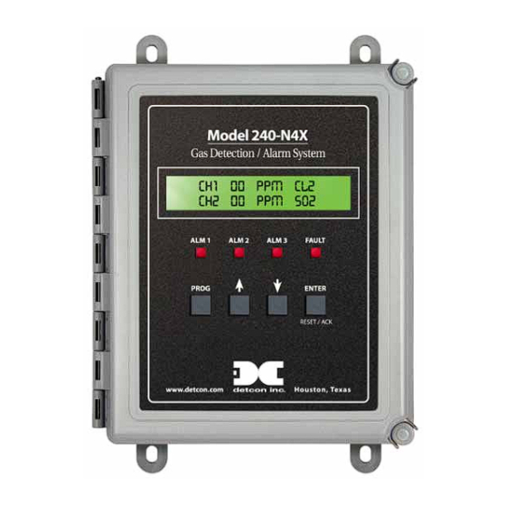
- Page 1 Model 240 Gas Detection/Alarm System Operator’s Installation and Instruction Manual DETCON, Inc. 3200 Research Forest Dr., The Woodlands, Texas 77387 Ph.281.367.4100 / Fax 281.298.2868 www.detcon.com November 1, 2010 • Document #2923 • Revision 1.8...
- Page 2 This page left intentionally blank Shipping Address: 3200 A-1 Research Forest Dr., The Woodlands Texas 77381 Mailing Address: P.O. Box 8067, The Woodlands Texas 77387-8067 Phone: 888.367.4286, 281.367.4100 • Fax: 281.292.2860 • www.detcon.com • sales@detcon.com Model 240 Operator Manual Rev. 1.8...
-
Page 3: Table Of Contents
Option for Battery Back-up Operation ......................26 Option for 4-20mA Output(s)........................26 Optional Interface PCB for Remote Display ....................26 Optional Remote Alarm Reset/Acknowledge Switch .................. 27 Optional Type Z Enclosure Purge Assembly ....................27 Model 240 Operator Manual Rev. 1.8... - Page 4 Figure 19 Optional Plug-in Module for 4-20mA Output and Remote Display ..............26 Shipping Address: 3200 A-1 Research Forest Dr., The Woodlands Texas 77381 Mailing Address: P.O. Box 8067, The Woodlands Texas 77387-8067 Phone: 888.367.4286, 281.367.4100 • Fax: 281.292.2860 • www.detcon.com • sales@detcon.com Model 240 Operator Manual Rev. 1.8...
-
Page 5: Description
Alarm Reset and Alarm Silence (Acknowledge) functions. The Model 240-N4X has a built-in power supply, giving the user a multitude of power options. It can be powered by either 115/230VAC or 11.5 to 30VDC, and has an optional one-hour battery backup in the event of temporary power loss. -
Page 6: System Operation
240 Operators Manual System Operation The Model 240-N4X can be configured for either two 4-20mA sensor inputs or two RS-485 serial sensor inputs via a dipswitch selection. The system displays current status information on its LCD display. The information displayed during normal operation includes the gas channel #, current reading and gas type. -
Page 7: Specifications
& type of gas sensor connected) Display 1”x5” Backlit LCD Electrical Classification NEMA 4X Dimensions 10”W x 12”H x 6”D -40F to +167F Operating Temperature Range -40C to +75C One year Warranty Model 240 Operator Manual Rev. 1.8 Page 3 of 29... -
Page 8: Installation
Installation 4.1 Mounting and Cable Penetrations Securely mount the Model 240 N4X enclosure per the mounting dimensions provided in Figure 2. Provide for suitable conduit/cable entries in the bottom of the enclosure. Keep AC power separate from DC signals in conduit connections and runs. -
Page 9: Dc Power
Operators Manual for the gas sensor that is being connected. Note: Analog sensor polling requires switch SW1-1 on the Control PCB to be set in the “OFF” position. (See Figure 5) Model 240 Operator Manual Rev. 1.8 Page 5 of 29... -
Page 10: Figure 4 Mother Board Layout
240 Operators Manual VOLTAGE SELECT POWER SWITCH BATTERY ON/OFF POWER SWITCH Battery Restore Switch Jumper for RS-485 Shield to Earth Grnd. Figure 4 Mother Board Layout Model 240 Operator Manual Rev. 1.8 Page 6 of 29... -
Page 11: Serial Input Gas Sensors
SW1-2 must be in the “ON” position (See Figure 5). NOTE: If VDC power for the Detcon Series 600 sensor is not available at the sensor location, then it can be provided via the + and – pins of channels 1 and 2 on the motherboard. The RS-485 wiring should be a 2 conductor, shielded twisted pair (Belden P/N 9841 is recommended). -
Page 12: Serial Polling Of The Model 140 Controller
4.2.6 Relay Outputs The standard Model 240 Controller provides four relays. Each relay has 2 Form C contacts. They can be used to fire annunciating devices or as signal inputs to other control devices. Connect to the relay contact terminals of the Motherboard PCB. There are two sets of terminals labeled FAULT, ALARM 1, ALARM 2, and ALARM 3 (Figure 4 –... -
Page 13: Start-Up
0 (zero) after a short warm-up period of 1-2 minutes. NOTE: All alarm relays will be disengaged for the first 1-minute after power-up to provide for an adequate sensor warm-up time. Model 240 Operator Manual Rev. 1.8 Page 9 of 29... -
Page 14: System Configuration
On the Controller PCB, switch SW1 position 1 is used to select between Analog and Serial sensor inputs for the 240 Controller. Switch SW1-1 must be placed in the “ON” position for the unit to accept Serial RS- 485 Modbus™ sensors, and SW1-1 must be placed in the “OFF” position if the sensors are 4-20mA type sensors (Figure 7). -
Page 15: Up Arrow" Key
Figure 8 Front Panel User Interface NOTE: The controller automatically times out of Menu Mode and returns to the Main Display after 1 minute of inactivity. Model 240 Operator Manual Rev. 1.8 Page 11 of 29... -
Page 16: Main Display Functions
6.5 User-Interface Menu Functions The User-Interface is conducted via the Model 240-N4X Front Plate shown above in Figure 8. The Menu Flow Chart (Figure 9) is navigated using the function keys described in Figure 8. User-Interface menu activity is conducted via the 1”x5”... -
Page 17: Menu Flow Chart
1200 - 1300 VIEW TWA / PEAK DATA TWA #### PK #### MAIN MENU 05/06/07 10:00:00 VIEW ALARM RECORDS REC# MESSAGE MAIN MENU DOWNLOAD HISTORY Figure 9 Menu Flow Chart Model 240 Operator Manual Rev. 1.8 Page 13 of 29... -
Page 18: Calibration Mode
This menu entry allows the selection of the Channel Range for each gas channel input. This is a scrolling list from 1.00 up to 10,000 and covers all of the Detcon gas sensor range possibilities. This menu appears SET CHANNEL RANGE: CH1 = XX.X... -
Page 19: Set Channel Alarms
The Main Display will show FAULT for any channel that is in FAULT. 6.5.8 Set Date and Time This menu entry allows for the correct entry of the current date and time. The menu appears as: SET DATE AND TIME: 01/26/04_14:56:07 Model 240 Operator Manual Rev. 1.8 Page 15 of 29... -
Page 20: Set Modbus Address
The duration of the recorded storage is 1 month for the TWA readings, Peak readings, and Event Records. Refer to Section 7.2 for complete procedure. DOWNLOAD HISTORY Model 240 Operator Manual Rev. 1.8 Page 16 of 29... -
Page 21: Alarm Test Mode
‘roll’ back to the maximum limit and start the cycle over. When the correct contrast level is obtained stop pressing the “up-arrow” key and the contrast will remain at that level. Model 240 Operator Manual Rev. 1.8... -
Page 22: System Features
System Features 7.1 Modbus Communications The model 240 controller features a Modbus compatible communications protocol and is addressable by a PLC, PC/HMI, DCS, or other Modbus RTU master polling device. Communications is accomplished by two wire half duplex RS-485, 9600 baud, 8 data bits, 1 stop bit, no parity, through the controllers secondary port. - Page 23 1 = Channel 1 Alarm 3 0 = Channel 1 no Alarm 3 40006 Cal Status Bits High Byte Bit 7 Not Used Bit 6 Not Used Bit 5 Not Used Model 240 Operator Manual Rev. 1.8 Page 19 of 29...
-
Page 24: Download Procedure
0 = Channel 1 no Cal 7.2 Download Procedure The Model 240-N4X Gas Detection Alarm System has very capable features in the area of data logging and event reporting. Continuous data for TWA and Peak readings are stored at 1-hour increments in permanent memory for retrieval. -
Page 25: Figure 10 Serial Connection And Jumper Locations
From the Start menu, select Programs> Accessories> Communications> Hyper Terminal. Figure 11 Invoking Hyper Terminal Hyper Terminal will open with the following Connection Description Dialog box. Type “X40 Download” as the name for the connection and click ‘OK’. Model 240 Operator Manual Rev. 1.8 Page 21 of 29... -
Page 26: Figure 12 Connection Description
Figure 13 Connect to Configuration The COM1 Properties Dialog box will appear. Insure the settings are: Bits per second: 9600 Data bits: 8 Parity: None Stop bits: 1 Flow control: None Click OK. Model 240 Operator Manual Rev. 1.8 Page 22 of 29... -
Page 27: Figure 14 Communications Port Properties
Select a Name and location where the downloaded data is to be saved, and click “Start”. The file will be saved as a text file and the file extension of *.txt should be used. Model 240 Operator Manual Rev. 1.8... -
Page 28: Figure 16 Naming Capture File
If the download was successful the display should look similar to figure 7 on the PC. Figure 17 Downloading information Once the data stream from the controller has been verified as stopped, select: Transfer> Capture Text> Stop from the main menu. Model 240 Operator Manual Rev. 1.8 Page 24 of 29... -
Page 29: Figure 18 Saving File
Disconnect the controller from the PC. The raw data from the controller is now stored in the file and location selected, and available for the user to use as desired. Model 240 Operator Manual Rev. 1.8 Page 25 of 29... -
Page 30: Options
An optional PCB that plugs into the controller board is available for 4-20mA outputs. This PCB has four channels of 4-20mA output. Only the first two channels are used with the 240 Control Unit. See Figure 19 for the correct installation and wire terminations for this feature. -
Page 31: Optional Remote Alarm Reset/Acknowledge Switch
This purge assembly achieves a Class 1, Division 2, Group CD area classification. The Type Z-Purge assembly is installed on the X40 Controller at the Detcon factory. The Z-Purge option is factory wired to automatically removed AC power from the controller if there is a loss of pressure. -
Page 32: Troubleshooting Guide
Date/Time Clock NICAD Battery Warranty Detcon, Inc., as the manufacturer, warrants under intended normal use each new Model 240-N4X controller to be free from defects in material and workmanship for a period of one year from the date of shipment to the original purchaser. -
Page 33: Revision Log
Revision Log Revision Date Changes made Approval 01/12/2009 Correction to Password Protection switch direction Section 6.2 11/1/2010 Correction to Note regarding use of Calibration Mode when sensors in calibration, Section 6.5.2 Model 240 Operator Manual Rev. 1.8 Page 29 of 29...
Need help?
Do you have a question about the 240 and is the answer not in the manual?
Questions and answers