Table of Contents
Advertisement
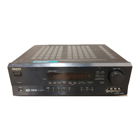
AV RECEIVER
MODEL
STANDBY/ON
STANDBY
A
SPEAKERS
B
DISPLAY
DIMMER
PHONES
AUDIO
SELECTOR
DVD
BMDD
SAFETY-RELATED COMPONENT
WARNING!!
COMPONENTS IDENTIFIED BY MARK
SCHEMATIC DIAGRAM AND IN THE PARTS LIST ARE
CRITICAL FOR RISK OF FIRE AND ELECTRIC SHOCK.
REPLACE THESE COMPONENTS WITH ONKYO
PARTS WHOSE PART NUMBERS APPEAR AS SHOWN
IN THIS MANUAL.
MAKE LEAKAGE-CURRENT OR RESISTANCE
MEASUREMENTS TO DETERMINE THAT EXPOSED
PARTS ARE ACCEPTABLY INSULATED FROM THE
SUPPLY CIRCUIT BEFORE RETURNING THE
APPLIANCE TO THE CUSTOMER.
SERVICE MANUAL
SERVICE MANUAL
HT-R510
SUBWOOFER
DIGITAL INPUT
MODE
MEMORY
FM MODE
TUNING
SPEAKER ADJUST
CLEAR
VIDEO
1
VIDEO
2
VIDEO
3
TAPE
TUNER
C D
VCR
Black models
120V AC, 60Hz
Ref. No. 3778
MASTER VOLUME
DIRECT
STEREO
SURROUND
DSP
PRESET/ADJUST
AUDIO ADJUST
VIDEO
3
INPUT
S VIDEO
VIDEO
L
AUDIO
R
ON THE
HT-R510
062003
Advertisement
Table of Contents

Related Manuals for Onkyo HT-R510


Summary of Contents for Onkyo HT-R510
- Page 1 COMPONENTS IDENTIFIED BY MARK ON THE SCHEMATIC DIAGRAM AND IN THE PARTS LIST ARE CRITICAL FOR RISK OF FIRE AND ELECTRIC SHOCK. REPLACE THESE COMPONENTS WITH ONKYO PARTS WHOSE PART NUMBERS APPEAR AS SHOWN IN THIS MANUAL. MAKE LEAKAGE-CURRENT OR RESISTANCE...
-
Page 2: Specifications
HT-R510 Specifications AMPLIFIER SECTION TUNER SECTION Continuous Average Power output (FTC) All channels: 100 watts per channel min. RMS at Tuning Range: 87.50-108.00 MHz (100 kHz steps) 8 Ω, 2 channels driven from 20 Hz Usable Sensitivity 11.2 dBf, 1.0 µV (75 Ω, IHF) Mono: to 20 kHz with no more than 0.08%... -
Page 3: Service Procedures
HT-R510 SERVICE PROCEDURES 1. Replacing the fuses This symbol located near the fuses indicates that the fuse used is fast operating type. For continued protection against fire hazard, replace with same type fuse. For fuse rating refer to the marking adjacent to the symbol. -
Page 4: Controls And Connectors
These buttons are used to turn speaker sets A and B on and off. STANDBY/ON button PHONES jack This button is used to set the HT-R510 to On or Standby. For models with a POWER switch, this button has no effect unless This 1/4-inch phone jack is for connecting a standard pair of the POWER switch is set to ON. - Page 5 These indicators display information about the currently selected source and listening mode. Tuning indicators TUNED: This indicator lights up when the HT-R510 is tuned into a radio station. AUTO: This indicator lights up when the Auto Tuning function is on.
-
Page 6: Rear Panel
These RCA/phono connectors can be used to connect a TV, example, a CD player, DVD player, or cassette recorder. The DVD player, or other AV component with component video HT-R510’s remote controller can then be used to control that inputs and outputs. component. To use... - Page 7 Press this to select STANDBY/ON button RCVR mode This button is used to set the HT-R510 to On or Standby. Listening mode buttons These buttons are used to select the listening modes. CINE FLTR button This button is used to set the Cinema Filter function.
-
Page 8: Supplied Accessories
Indoor FM antenna Speaker cable labels two batteries (AA/R6) * In catalogs and on packaging, the letter added to the end of the product name indicates the color of the HT-R510. Specifications and operation are the same regardless of color. Features FM/AM Tuner •... -
Page 9: Exploded View
HT-R510 EXPLODED VIEW P901 P101 P7502 F6901 P7503 F6902 Q6050 Q6060 Q6055 Q6065 T901... -
Page 10: Block Diagram
HT-R510 BLOCK DIAGRAM To Main microprocessor BD3811K1 FM/AM TUNER PACK VIDEO3 INPUT GAIN 0/6dB INPUT GAIN TAPE OUT 0/6dB INPUT GAIN TAPE IN 0/6dB INPUT GAIN VIDEO3 0/6dB VIDEO-2 IN INPUT GAIN 0/6dB VIDEO-1 OUT INPUT GAIN 0/6dB VIDEO-1 IN... - Page 11 HT-R510 BLOCK DIAGRAM MASTER HEADPHONE VOLUME Power Amplifier 0~103dB BASSBOOST OUTPUT GAIN +27dB BASS/TREBLE 0~18dB OPAMP OUTPUT +27dB BASS/TREBLE GAIN 0~18dB OPAMP SPBL OUTPUT GAIN SPBR +27dB 0~18dB OPAMP OUTPUT GAIN +27dB 0~18dB OPAMP OUTPUT GAIN +27dB 0~18dB OPAMP OUTPUT GAIN...
-
Page 12: Schematic Diagram
HT-R510 SCHEMATIC DIAGRAM 1-1 Display and video sections NADIS-7403 Q7501 HNA-16MM39T P46/FIP38 P47/FIP39 FIP18 62 61:FIP19 P50/FIP40 FIP17 63 P51/FIP41 FIP16 64 P52/FIP42 FIP15 65 P53/FIP43 FIP14 66 P54/FIP44 FIP13 67 Q7502 P55/FIP45 FIP12 68 P56/FIP46 FIP11 69 P57/FIP47 FIP10 70... - Page 13 HT-R510 SCHEMATIC DIAGRAM 1-2 Display and video sections NAETC-7838 NAVD-7847 +12V C227 223Z CNPT VIDEO-2 C201 VIN4 2.2/50 P201 VIN3 VMUT2 VMUT1 R205 C203 OPT2 470/16 VIDEO-1 C220 DGND VIN2 223Z OPT1 C202 2.2/50 R208 COAX P202 R202 680K VIN1...
- Page 14 HT-R510 SCHEMATIC DIAGRAM 2-1 Digital and main microprocessor sections 78L07 Q321 R300 R6402 Q6402 Q322 +12VAF 79L07 C6403 1/2W Q9501 C6404 223Z 78M12 2SA1015-G 10/16 R6403 R301 Q6403 KTA1266- R302 -22V -12VAF C6406 C6405 1/2W TAPE-1 OUT 10/16 223Z C9512...
- Page 15 HT-R510 SCHEMATIC DIAGRAM 2-2 Digital and main microprocessor sections +22V SEC1-1 SEC1-2 SEC3-1 P101 TO TUNER PACK P801 SEC3-2 Q9501 5.6S 2SA1015-GR D9502-9505: R9506 KTA1266-GR 1SR154-400 PROTHERM -22V C9507 1/2W D9507 RL1N4003 C9512 220/35 R9507 223Z R9508 C103 3.3/50 C9505...
- Page 16 HT-R510 SCHEMATIC DIAGRAM 3-1 Driver circuit section NAAF-7830 P406 R5163 120(1/4W) 58.0V R5113 R5183 56.6V 57.2V R5093 (1/4W) Q5033 100K 1.1V C5053 Q5003 Q5013 C5103 47/50 C5013 R5003 040D -0.1V 10/100 22/16 -0.7V R5013 R5023 R5033 C5003 R5053 101K 4.7K C5043 -52.5V...
- Page 17 HT-R510 SCHEMATIC DIAGRAM 3-2 Driver circuit section TO NADG-7821 (PART-2) P406A P306A R5160 120(1/4W) 58.0V R5110 R5180 56.6V 57.2V R5090 (1/4W) Q5030 100K 1.1V C5050 Q5000 Q5010 C5100 47/50 C5080 C5010 10/63 R5000 040D -0.1V 22/16 10/100 -0.7V R5010 R5020...
-
Page 18: Power Amplifier Section
HT-R510 SCHEMATIC DIAGRAM 4-1 Power amplifier section NAAF-7842 [58.2V] Q6033 [1.1V] R6033 R6163 R6083 [0.5V] Q6053 [1V] (1/4W) [0.5V] Q6073 R6143 P6083 R6003 [0V] R6073 5.6K [0.2V] R6103 R6013 0.22 X2 (1/4W) (2W) 3.9K Q6013 R6153 [-0.3V] [0V] Q6023 R6093... - Page 19 HT-R510 SCHEMATIC DIAGRAM 4-2 Power amplifier section [58.2V] Q6030 [1.1V] R6030 R6080 R6160 [0.5V] Q6050 (1/4W) [1V] [0.5V] R6140 Q6070 P6080 [0V] R6070 [0.2V] R6100 0.22 X2 (1/4W) (2W) Q6010 R6150 [-0.3V] [0V] R6190 Q6020 R6090 R6040 Q6060 330K [-0.5V] [-0.5V]...
- Page 20 HT-R510 SCHEMATIC DIAGRAM 5-1 Power supply and Speaker terminal sections NAETC-7835 C6600 103J SPEAKER-B D6600 RL6600 LSSP RL6601 RSSP SBSP FRONT SPEAKER D6601 103Z C6601 P6802 SURROUND SPEAKER CENTER D6604 C6604 103J BRLD FRLD CSRLD +24V LSPE RSPE CSPE LSSPE...
- Page 21 HT-R510 SCHEMATIC DIAGRAM 5-2 Power supply and Speaker terminal sections NAETC-7833 FLAC1 FLAC2 MPUGND MPUGND AGND 5.6V +5.6V C6933 Q6931 10/16 NJM78M56FA +24V S3GND S3GND 17.8V C6932 103Z D6933 C6931 R6935 1000/25 +5.6V D6932 PROTHERM (2W) D6932,6933: GP104003E OR POWER...
-
Page 22: Video Section
HT-R510 SCHEMATIC DIAGRAM 6 Video section NAVD-7831 COMPONENT OUT CR(PR) COMPONENT CB(PB) RL242 RL241 P241 P241 D241 C241 103Z CR(PR) COMPONENT Q241 CB(PB) R249 IN 2 2SC1740 P241 P243B TO NAETC-7838... -
Page 23: Wiring View
HT-R510 WIRING VIEW NAETC-7835,Speaker terminal PC board ass'y P6801 P6800 P6802 JL6804B JL6805B NCETC-7835 JL6803B NAPS-7845,Primary circuit PC board ass'y S902 P902 P925 P926 P6801 P6802 E921 220V P911 120V JL6803A P922A JL6805A P921A P917 P918 P913 P912 T902 P922... - Page 24 HT-R510 WIRING VIEW NAETC-7849, Thermal detector PC board ass'y NAETC-7406, Front video P305 P304 P302 P301 P351 P261B P253B PC board ass'y NAETC-7838, Connector PC NADG-7821, board ass'y DSP circuit PC board ass'y P253A NAVD-7847,Video circuit PC board ass'y P281...
-
Page 25: Printed Circuit Board View
HT-R510 PRINTED CIRCUIT BOARD VIEW 1 NADIS-7403,Display circuit PC board P7503A P7502A R7580 Q7501 J7548 J7544 STEREO DIRECT C7502 J7549 J7524 U7501 S7641 S7501 S7642 J7525 C7521 SURROUND J7512 J7538 S7501 S7643 S7644 J7528 J7537 C7514 J7539 J7526 PRESET ADJUST... - Page 26 HT-R510 PRINTED CIRCUIT BOARD VIEW 1 NAETC-7405,Headphone terminal PC board R7581 R7582 7501 E7501 J7551 J7573 Q7501 J7574 J7572 J7571 P7501 JL7502B D7505 P7501 NCETC-7405 25137405 X7501 J7506 Component side J7507 J7541 J7533 S7611 S7612 S7627 J7535 HPDET S7613 S7621...
- Page 27 HT-R510 PRINTED CIRCUIT BOARD VIEW 2 NADG-7821, DSP circuit PC board L7002 C7015 P802 C722 Q705 L703 D9506 C714 R705 Q705 C702 D9510 R748 D9507 D9512 Q704 C9507 R751 R752 R753 D9509 C9507 C9510 R754 C9510 Q704 R755 R756 D9511...
- Page 28 HT-R510 PRINTED CIRCUIT BOARD VIEW 2 NADG-7821, DSP circuit PC board R321 C321 R343 C320 R342 R320 R319 C319 R341 R340 C318 R318 C326 R317 C317 R339 R338 C818 C821 C316 C822 R316 R725 L806 R724 R723 R826 R315 R722...
- Page 29 HT-R510 PRINTED CIRCUIT BOARD VIEW 4 Q6015 Q6014 Q6013 Q6012 Q6055 Q6054 Q6053 Q6065 Q6064 Q6063 Q6062 R6094 R6093 R6092 J6184 J6165 J6132 R6095 J6185 J6177 J6166 J6153 J6141 J6123 J6178 J6175 J6159 J6150 J6130 J6128 J6179 J6176 J6160 J6151...
- Page 30 HT-R510 PRINTED CIRCUIT BOARD VIEW 4 Q6013 Q6012 Q6011 Q6010 Q6053 Q6052 Q6051 Q6050 Q6062 Q6061 Q6060 R6090 R6092 R6091 J6132 J6099 J6059 J6141 J6123 J6122 J6080 J6060 J6033 J6014 J6130 J6128 J6094 J6092 J6053 J6031 J011A J010A J6131 J6129...
- Page 31 HT-R510 PRINTED CIRCUIT BOARD VIEW 5 P6801 P6800 P6802 P6801 C6846 J5326 C6853 J5304 P6802 L6800 P6800 C6855 C6852 C6851 J5314 RL6604 C6854 C6841 RL6601 R6810 RL6603 R6815 L6801 L6805 L6800 RL6604 RL6600 RL6603 J5305 J5320 R6805 R6800 R6814 L6804...
- Page 32 HT-R510 PRINTED CIRCUIT BOARD VIEW 5 NCPS-7845 25137845 P901A AC-G AC-H J6310 P909 P908 AC-H AC-G J6302 T2.5AL250V F903 J6305 J6312 F903B J6304 J6311 F903A 6.3A/125V J6315 J6316 F901 F901B C901 C901 F901A J6313 F902B RL901 F902A F902 RL901 J6308...
- Page 33 HT-R510 PRINTED CIRCUIT BOARD VIEW 3 R5170 Video section R5070 R5080 Q5050 D5000 J5003 R5100 C5040 C5090 J5002 R5020 R5130 R5010 C5110 R5180 P206B Q5030 C5010 J237 R5000 J230 R5190 C5000 J5005 Q281 J238 J5014 J5007 J5006 J5008 P5001 Q205...
-
Page 34: Ic Block Diagrams And Descriptions
HT-R510 IC BLOCK DIAGRAMS AND DESCRIPTIONS AK4384(106dB 192kHz 24-Bit 2ch DAC ) MCLK MCLK DZFL Clock De-emphasis SMUTE/CSN µP BICK DZFR Control Divider VCOM ACKS/CCLK Interface SDTI DIF0/CDTI DZFL LRCK DZFR View VCOM AOUTL Modulator Interpolator LRCK Audio SMUTE/CSN AOUTL... - Page 35 HT-R510 IC BLOCK DIAGRAMS AND DESCRIPTIONS AK4586VQ(96kHz 6ch CODEC) No. Name Description Crystal oscillator output pin Crystal oscillator input pin EXTCLK Master clock input pin XTI/EXTCLK TVDD Power supply pin for output buffer. 2.7V to 5.5V DVSS Digital ground pin...
- Page 36 HT-R510 IC BLOCK DIAGRAMS AND DESCRIPTIONS BD3811K1(6ch Volume with 8ch input selector) No. Terminal Description INDSPSL DSP surround Lch input terminal INDSPC DSP center input terminal INDSPSW DSP sub woofer input terminal I N 3 1 T N F 2...
- Page 37 HT-R510 IC BLOCK DIAGRAMS AND DESCRIPTIONS BD3812F(Audio Sound Processor) OUT1 1ch input 1ch output AGND1 OUT2 Analog ground 2ch output 2ch input Serial data select AGND2 DGND Analog ground Comparator ground MUTE (-)Power supply Mute AGND3 LOGIC Analog ground Serial data...
- Page 38 HT-R510 IC BLOCK DIAGRAMS AND DESCRIPTIONS CS493264(DSP IC) SCDIO, DATA7:0, R/W, SCDOUT, EMAD7:0, EMOE, EMWR, PSEL, ABOOT, EXTMEM, GPIO7:0 SCCLK SCDIN INTREQ GPIO8 RESET GPIO11 GPIO10 GPIO9 CMPDAT, SDATAN2 PARALLEL or SERIAL HOST INTERFACE COMPRESSED CMPCLK, DATA INPUT SCLKN2 INTERFACE...
- Page 39 HT-R510 IC BLOCK DIAGRAMS AND DESCRIPTIONS TC74VHC541FT(Octal bus buffer) TC7HTC7007AF(Hex buffer) INPUTS OUTPUT X :Don't care Z :High impedance 74HCU04F(Hex Inverter) TC7WU04FU(Triple inverter) Truth table (TOP VIEW) TC74VHC574FT(Octal D-FF with 3-state output) INPUTS OUTPUT CK Q CK Q CK Q...
- Page 40 HT-R510 RL241,2 MAIN MICROPROCESSOR-CONNECTION DIAGRAM RL901 Q241 Q921 COMPONENT VIDEO POWER Q7006,Q205 Q201,Q207,Q208 VIDEO 2 VIDEO 1 RELAY RELAY SW MUTE DRIVE MUTE SW CIRCUIT Q7007,Q206 Q202,Q210,Q211 RL6600 VIDEO 1 VIDEO 2 MUTE DRIVE MUTE SW RL6603, CIRCUIT Q6601 RL6604...
-
Page 41: Connection Diagram
HT-R510 SUB-MICROPROCESSOR CONNECTION DIAGRAM Q7501 FL TUBE HNA-16MM39T FIP19 P46/FIP38 40 FIP18 P47/FIP39 39 P50/FIP40 38 FIP17 FIP16 P51/FIP41 37 FIP15 P52/FIP42 36 FIP14 P53/FIP43 35 FIP13 P54/FIP44 34 FIP12 P55/FIP45 33 FIP11 P56/FIP46 32 Q7502 P57/FIP47 31 FIP10 FIP9... - Page 42 HT-R510 TERMINAL DESCRIPTION MAIN MICROPROCESSOR No. Terminal I/O Description PROTECT Protection circuit detection input terminal VOLH Power amplifier voltage detection terminal. BAND Region setting input terminal. 11 232TXD Not used. 15 MCRDY Data ready detection input terminal from the sub microprocessor.
- Page 43 HT-R510 TERMINAL DESCRIPTION SUB MICROPROCESSOR Pin No. Symbol I/O Description Pin No. Symbol I/O Description Power supply terminal. Connect to 5V. Segment output terminal of P22. Ground terminal. Segment output terminal of P21. Ceramic oscillator connection terminals for main system.
-
Page 44: Adjustment And Confirmation Procedures
HT-R510 ADJUSTMENT AND CONFIRMATION PROCEDURES 1 Idling current adjustment Before Idling adjustment, turn the trimming resistors R6040,R6041,R6042,R6043 and R6044 to counter clockwise. Connect the DC voltmeter to sockets P6080,P6081,P6082,P6083,P6084 and P6085. After turn POWER to ON, adjust the trimming resistors R6040,R6041 and R6042 so that the reading of voltmeter becomes 2.5 mV. -
Page 45: Test Mode
HT-R510 ADJUSTMENT AND CONFIRMATION PROCEDURES 2 3. Confirmation of Current detection circuit Set the unit to "TEST-1-00". Connect the differentiating circuit and apply the 200Hz square signal to DVD INPUT terminal of each channel. Adjust the attenuator or Volume so that the output level becomes 35V p-p. -
Page 46: Packing Procedures
HT-R510 PACKING PROCEDURES Bottom Accessary bag Put the label 81 between page 2 and page 3 of instruction manual E. Speaker Cable... -
Page 47: Exploded View Parts List
EXPLODED VIEW-PARTS LIST REF. NO. PART NO. DESCRIPTION 27111268 Front bracket 838130088 3TTB+8B,Self-tapping screw 27100416A Chassis 27190503A KGLS-8RT,Holder 27190813 KGPS-10RF,Holder 27190428A KGLS-10RT,Holder 830440089 4TTC+8C(BC),Self-tapping screw 880009 NRP-345,Plastic rivet 27300750 ! Cord, bushing 27160527 Heatsink 801606 3SMH10W.SW+15B(CU),Special screw 28184831 Top cover 838430088 3TTB+8B(BC),Self-tapping screw 29363194... - Page 48 Q6050,Q6051 2202843, * 2SC5242-O, 2202842, * 2SC5242-R 2203684, * MN150S-Y, 2203686 or * MN150S-P or 2203683 * MN150S-O, Q6052~Q6055 2203563, * KTC5242-O, 2203562, * KTC5242-R, 2203664, * MN130S-Y, 2203666, * MN130S-P, 2203663, * MN130S-O, 2202843 or * 2SC5242-O or 2202842 * 2SC5242-R Q6060,Q6061 2202833 or * 2SA1962-O or...
- Page 49 1A970533-1D NAETC-7833-1D,Const. Voltage circuit PC board ass'y 1A970534-1D NAPS-7834-1D,Secondary circuit PC board ass'y 1A970535-1D NAETC-7835-1D,Speaker terminal PC board ass'y 1A970536-1D NAETC-7836-1D,Ground terminal PC board ass'y 1A970538-1D NAETC-7838-1D,Connector PC board ass'y 1A970542-1H NAAF-7842-1H,Power amplifier PC board ass'y 1A970544-1H NAPS-7844-1H,Transformer terminal PC board ass'y 1A970545-1H NAPS-7845-1H,Primary circuit PC board ass'y 1A970546-1H...
-
Page 50: Packing Parts List
PACKING-PARTS LIST REF. NO. PART NO. DESCRIPTION 29092044 29100034-1A 850*650,Polybag 29110149 Tape, cellophane 29110148 PP tape 29100201 350*200*W250,Polybag 29054020 Carton box <B> 29054115 Carton box <S> 29363326 Label UPC <B> 29363547 Label UPC <S> 29363059A Label,cable 29343479A Instruction manual E 29343480 Instruction manual, digest 24140518... -
Page 51: Printed Circuit Board-Parts List
PRINTED CIRCUIT BOARD-PARTS LIST Display circuit PC board (NADIS-7403-2C) CIRCUIT NO. PART NO. DESCRIPTION FL tube Q7501 212229 HNA-16MM39T Sensor U7501 241341 SPS-444-1-E1,Remote control Q7502 22241571R3 MPD780232GC-030-8BT Transistors Q7503 2216175R2 or KTC3875-GR or 2213145R2 2SC2712-GR Q7504 2216230R2 or KRA103S or 2214540R2 RN2403 Q7506... - Page 52 25035699 or NPS-111-S662 or 25035714 NPS-111-S677 Sockets JL7501A 25051107 NSCT-3P894 JL7502A 25051109 NSCT-5P896 P7502A 25051892 or NSCT-10P1679 or 25052477 NSCT-10P2374 P7503A 25052054 or NSCT-8P1841 or 25051852 NSCT-8P1639 Holder Q7501A 27190989A (FL) Standby switch PC board (NASW-7404-2C) CIRCUIT NO. PART NO. DESCRIPTION Push switches S7614~S7616...
- Page 53 Q6402,Q6405 222780125 78M12HF Q6403 222790125 79M12HF Q6406 222780055 78M05HF Q7002 22274541ER2TO or TC74VHC541FT or 22274541IR2TI SN74AHC541PWR Q7003 222740077R2TO TC74HCT7007AF Q7004 22241778R2 BA33C25FP Q7008 22242167R3 MPD784225GC-253-8BT-A(MASK) Q701 22241788R2 CS493292-CLR(6.1ch) 22241795R3 Q702 MX27L2000(TX-SR600) DISCON Q704,Q705 22274574ER2TO or TC74VHC574FT or 22274574IR2TI SN74AHC574PWR Q707 22240935R2 TC7WU04FU Q801...
- Page 54 CIRCUIT NO. PART NO. DESCRIPTION Choke coils L7001,L703 231237K470R2 or NCH-1479 or 233533K470R2 NCH-1587-470K L7002,L701 231237M022R2 or NCH-1471 or L702,L704 233533K022R2 NCH-1587-022K L705,L706 230958R1 BK1608LM182-T L801~L804 231237M022R2 or NCH-1471 or L806 233533K022R2 NCH-1587-022K L805 230958R1 BK1608LM182-T Oscillators X7001 3010361R2 CSTCE12M5G52-R0,Ceramic X701 3010324R2 CSTCV12.2MTJ0C4,Ceramic...
- Page 55 394644707 CE04W16V-47M(VR),Elect. C806 394724717 or CE04W6.3V470M(SC) or 394624717 CE04W6.3V-470M(VR),Elect. C809,C820 394741007 or CE04W16V10M(SC) or 394641007 CE04W16V-10M(VR),Elect. C822 394722217 or CE04W6.3V220M(SC) or 394622217 CE04W6.3V-220M(VR),Elect. C832~C837 393341007 CE04W16V-10M(VX),Elect. C841 373048224R2 ECHU16V-822J,Chip film C849 373041534R2 ECHU16V-153J,Chip film C852,C853 374721524 ECQ-B50V-152J,Plastic film C854 393341007 CE04W16V-10M(VX),Elect.
- Page 56 Plugs P261A 25055133 NPLG-3P117 P410B 25055707 NPLG-11P663 P411B 25055706 NPLG-10P662 P412B 25055704 NPLG-8P660 P801 25055711 NPLG-15P667 Heat sink Q6402B 27160526 RAD-183 Screws Q6402A,Q6405A 82143010 3P+10FN(BC),Pan head Q6406A 82143010 3P+10FN(BC),Pan head Driver circuit PC board (NAAF-7830-1D) CIRCUIT NO. PART NO. DESCRIPTION Transistors Q5000~Q5005 2215896,...
- Page 57 C5110~C5115 394691007 CE04W100V-10M(VR),Elect. CIRCUIT NO. PART NO. DESCRIPTION Resistors R5160~R5165 415471214 R25J-120,NF carbon R5170~R5175 415471214 R25J-120,NF carbon R5180~R5185 415471004 R25J-10,NF carbon R5190~R5195 415471004 R25J-10,NF carbon Sockets P6000A~P6005A 25052288 NSCT-5P2185 P6011A 25052293 NSCT-10P2190 Plug P306A 25055376 NPLG-12P359 Bus bar P5001 27141867 BBL40 Component video PC board (NAVD-7831-1D) CIRCUIT NO.
- Page 58 C6933 394641007 or CE04W16V-10M(VR) or 394741007 CE04W16V10M(SC),Elect. Resistor R6935 441721214 RS2WBJ-120,Metal oxide Sockets JL9501A 25051111 NSCT-7P898 P410A 25051236 NSCT-11P1026 P411A 25051235 NSCT-10P1025 P6931A 25051527 NSCT-16P1314 P7503B 25052241, NSCT-8P2138, 25051312, NSCT-8P1101, 25051852 or NSCT-8P1639 or 25052054 NSCT-8P1841 Secondary circuit PC board (NAPS-7834-1D) CIRCUIT NO.
- Page 59 CIRCUIT NO. PART NO. DESCRIPTION P206A 25055711 NPLG-15P667,Plug P243A 25055804 NPLG-4P760,Plug P801B 25051240 NSCT-15P1030,Socket Power amplifier PC board (NAAF-7842-1H) DESCRIPTION CIRCUIT NO. PART NO. Transistors Q6010~Q6015 2213284 or 2SC1740S-R or 2213285 2SC1740S-S Q6020~Q6025 2213284 or 2SC1740S-R or 2213285 2SC1740S-S Q6030~Q6035 2203434 or KTD2061-Y or 2203010...
- Page 60 CIRCUIT NO. PART NO. DESCRIPTION Diodes D6000~D6005 223163, 1SS133, D6010~D6015 223205 or 1SS270A or D6306,D6307 223222 WG713A D6701,D6702 223163, 1SS133, D6906 223205 or 1SS270A or 223222 WG713A D6703,D6704 224470512 MTZJ5.1B D6903,D6904 22380130, D5SBA20, 22380038 or RBV602 or 22380274 RS603M-B42 Capacitors C6040~C6045 394684707 CE04W50V-47M(VR),Elect.
- Page 61 25065515 or NRL-1P5A-DC12-096 or 25065526 NRL-1P5A-DC12-102 Fuse holders F6901A,F6901B 25052133 NSCT-1P2031 F6902A,F6902B 25052133 NSCT-1P2031 Sockets JL6402A 25051087 NSCT-3P874 JL6803A,JL6804A 25051110 NSCT-6P897 JL6805A 25051108 NSCT-4P895 JL6951A,JL6952A 25051109 NSCT-5P896 Plugs P6000~P6005 25056010 NPLG-5P0960 P6011 25056015 NPLG-10P0965 P6080~P6085 25055038 NPLG-2P29 P6301 25055042 NPLG-3P32 P6931 25055805 NPLG-16P761...
- Page 62 25065508, ! NRL-1P10A-DC12-093, 25065515 or ! NRL-1P5A-DC12-096 or 25065526 ! NRL-1P5A-DC12-102 Fuse holders F901A,F901B 25052133 NSCT-1P2031 Sockets P902 25051571 ! NSCT-2P1358 P931A 25051230 NSCT-5P1020 Plug P901A 25055675 or ! NPLG-2P631 or 25056028 ! NPLG-2P0978 Label F901C 29360842 Fuse Secondary terminal PC board (NAPS-7846-1H) CIRCUIT NO.
- Page 63 Video circuit PC board (NAVD-7847-1H) CIRCUIT NO. PART NO. DESCRIPTION Q203 22241759 LA7956 Q212,Q213 22241759 LA7956 Q281 222740046R2 74HCU04F Photo couplers U281,U282 24120101 TORX179L Transistors Q201,Q202 2213631 or RN1241-A or Q207,Q208 2213632 RN1241-B Q204,Q209 2215995 or KTA1267-GR or 2213354 2SA933S-R Q205,Q206 2215770 or KRA102M or...
- Page 64 Plug P253A 25055236 NPLG-5P220 Thermal detector PC board (NAETC-7849-1H) CIRCUIT NO. PART NO. DESCRIPTION R6380 4000153 PTH9M04BF222TS2F333,Thermistor JL6402B 25051087 NSCT-3P874,Socket...
- Page 65 Sales & Product Planning Div. : 2-1, Nisshin-cho, Neyagawa-shi, OSAKA 572-8540, JAPAN Tel: 072-831-8111 Fax: 072-833-5222 ONKYO U.S.A. CORPORATION 18 Park Way, Upper Saddle River, N.J. 07458, U.S.A. Tel: 201-785-2600 Fax: 201-785-2650 E-mail: onkyo@onkyousa.com ONKYO EUROPE ELECTRONICS GmbH Liegnitzerstrasse 6, 82194 Groebenzell, GERMANY Tel: +49-8142-4401-0 Fax: +49-8142-4401-555 E-mail: info@onkyo.de...
Need help?
Do you have a question about the HT-R510 and is the answer not in the manual?
Questions and answers