Table of Contents
Advertisement
Quick Links
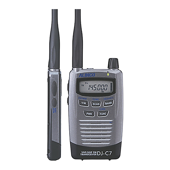
DJ - C7 T/E
Service Manual
CONTENT
S
S
General.....................................................
Transmitter................................................
Receiver...................................................
1)
Receiver System......................................
2)
Transmitter System...................................
3)
M38268MCL069GP (XA1023)....................
1)
NJM2070M (XA0210)..............................
2)
TC4W53FU (XA0348) .............................
3)
XC62HR3302MR (XA0519).......................
4)
BA4510FV (XA0537)...............................
5)
NJM2904V (XA0573)...............................
6)
TK10931V (XA0666)................................
7)
BU9831F (XA0882).................................
8)
uPC2771TB (XA0953)..............................
9)
uPC2757TB (XA0976)...............................
10) BR24L32FV (XA1008)..............................
11) BD4930FVE (XA1009)..............................
12) MB15A01PFV1 (XA1010).........................
13) XC6383A701MR (XA1012)........................
14) MM1438BW (XA1013).............................
15) TC75S51FU (XA1014)..............................
17)
LCD Connection (A48A002X).....................
1)
Front View.............................................
2)
Rear View..............................................
2
MAIN Unit................................................
2
KEY Unit..................................................
2
BATTERY Unit...........................................
PTT Unit..................................................
ROTARY ENCODER Unit.............................
Mechanical Parts.........................................
3-5
Packing Parts.............................................
6
7-9
1)
Required Test Equipment.............................
2)
10
10
10
10
11
11
11
12
12
12
12
13
13
14
14
15
16
17
18
ALINCO, INC.
................................
.....................
..............................
www.ALINCO.ru
19-22
22-23
23
23
23
23
23
24
25-28
29-33
34-35
36
Advertisement
Table of Contents

Related Manuals for Alinco DJ - C7 T


Summary of Contents for Alinco DJ - C7 T
-
Page 1: Table Of Contents
(XA0953)………………………… uPC2757TB (XA0976).….……………….……. 10) BR24L32FV (XA1008)………………………... 11) BD4930FVE (XA1009)…..……………………. 12) MB15A01PFV1 (XA1010)……………….…… 13) XC6383A701MR (XA1012).………………….. 14) MM1438BW (XA1013).………………….…… 15) TC75S51FU (XA1014)………………………... 16) Transistor, Diode and LED Outline Drawing….. LCD Connection (A48A002X)…………….….. EXPLODED VIEW Front View…………….……………………….. Rear View……………………….………….….. ALINCO, INC. www.ALINCO.ru... -
Page 2: Specifications
SPECIFICATIONS General Type DJ – C7T DJ-C7E 144.000 – 147.995MHz 144.000 – 145.995MHz Transmitter Range 420.000 – 449.995MHz 430.000 – 439.995MHz 88.100 – 1.7.995MHz 87.500 – 107.995MHz Receiving Range 108.000 – 173.995MHz 144.000 – 145.995MHz 380.000 – 511.995MHz 430.000 – 439.995MHz Modulation Operating temperature -10 °C ~ 60°C (+14°F ~ +140°F) -
Page 3: Circuit Description
CIRCUIT DESCRIPTION 1) Reception 1. RX Method [FM/AM] Double Super Heterodyne Method 1st IF: 50.85MHz 2nd IF: 450kHz [WFM] Single Super Heterodyne Method 1st IF: 10.7MHz 2. Front End [WFM BAND] The signal input from antenna passes through the low pass filter, and then it is amplified at RF amplifier Q13. - Page 4 4. IF [FM/AM] The signal amplified at the 1st IF amplifier Q15 is supplied to pin 24 of IC7 for demodulation. Also the signal of 12.6 MHz from the reference buffer output of IC2 is multiplied by 3 at Q12, and then it is led to pin 1 of IC7. 2 input signals are mixed in the mixer circuit inside IC7 and converted into the 2nd IF signal of 450kHz.The converted 2nd IF signal is output from pin 3 of IC7.
- Page 5 7. VCO [VHF] VCO in VHF band consists of the Colpitts oscillator. D3, D4 and L11 determine the oscillating frequency, and the signal is oscillated at the transistor Q2. The oscillated signal is supplied to pin 8 of PLL-IC2 passing through the buffer amplifier Q5 and Q4.
-
Page 6: Transmitter System
2) Transmitter 1. Microphone Amplifier The microphone amplifier IC301 has 2 operational amplifiers. The voice is converted into the electric signal through the microphone, and then supplied to IC301. The input signal is amplified and pre-emphasized to be output. [VHF] The signal output from microphone amplifier is adjusted the maximum frequency deviation at VR2. -
Page 7: M38268Mcl069Gp (Xa1023)
3) M38268MCL069GP (XA1023) Terminal Connection (TOP VIEW) - Page 8 Terminal Signal Description P67/AN7 Band plan 1 P66/AN6 BCHK Battery detection input P65/AN5 PCNT Battery detection SW output P64/AN4 S-meter input P63/SCLK22/AN3 Noise level input for squelch P62/SCLK21/AN2 CTCSS Tone input P61/SOUT2/AN1 TX LED SW output P60/SIN2/AN0 Battery charge voltage input P57/ADT/DA2 TUNC/TONE RX Tuning/Tone out...
- Page 9 Terminal Signal Description P13/SEG37 W/NC Wide / Narrow SW output P12/SEG36 FM SW output P11/SEG35 T3V power ON/OFF SW output P10/SEG34 TSWC Tone power ON/OFF SW output P07/SEG33 UHF-TX power ON/OFF SW output P06/SEG32 VHF-power ON/OFF SW output P05/SEG31 BD3C BND3 power SW output P04/SEG30 BD4C...
-
Page 10: Semiconductor Data 1) Njm2070M (Xa0210)
www.ALINCO.ru... -
Page 15: Transistor, Diode And Led Outline Drawing
16) Transistor, Diode and LED Outline Drawings Top View... -
Page 16: Lcd Connection (A48A002X)
17) LCD Connection (EL0056 A48A002X) SEGMENT COMMON... -
Page 17: Exploded View
EXPLODED VIEW 1) Front View... -
Page 18: Rear View
2) Rear View... -
Page 19: Parts List
PARTS LIST MAIN Unit Ref. Ref. Parts No. Description Parts Name Version Parts No. Description Parts Name Version FG0374 LCD RUBBER CU3515 Chip C. GRM36CH220J50PT FM0232 LCD FRAME CU3547 Chip C. GRM36B103K16PT ST0082 LCD HOLDER DJC7 CU3523 Chip C. GRM36CH101J50PT TS0174 VCO CASE DJC7 CU3531... - Page 20 Ref. Ref. Parts No. Description Parts Name Version Parts No. Description Parts Name Version C141 CU3531 Chip C. GRM36B471K50PT XD0381 Chip Diode MA27077 C142 CU3531 Chip C. GRM36B471K50PT XD0364 Chip Diode 1SV279-TPH3 C143 CU3506 Chip C. GRM36CH050C50PT XD0364 Chip Diode 1SV279-TPH3 C144 CU3513...
- Page 21 Ref. Ref. Parts No. Description Parts Name Version Parts No. Description Parts Name Version QC0592 Chip Inductor LQW1608A47NJ00T1 RK3530 Chip R. 1005 1/16W 220 OHM J QC0718 Chip Inductor LQW1608AR33J00T1 RK3550 Chip R. 1005 1/16W 10K OHM J QC0597 Chip Inductor LQW1608AR12J00T1 RK3536 Chip R.
-
Page 22: Key Unit
Ref. Ref. Parts No. Description Parts Name Version Parts No. Description Parts Name Version RK3574 Chip R. 1005 1/16W 1.0M OHMJ R167 RK3550 Chip R. 1005 1/16W 10K OHM J RK3574 Chip R. 1005 1/16W 1.0M OHMJ R168 RK3542 Chip R. 1005 1/16W 2.2K OHMJ RK3574 Chip R. -
Page 23: Battery Unit
Ref. Parts No. Description Parts Name Version Mechanical Unit R324 RK3538 Chip R. 1005 1/16W 1.0K OHMJ Ref. R325 RK3538 Chip R. 1005 1/16W 1.0K OHMJ Parts No. Description Parts Name Version R326 RK3559 Chip R. 1005 1/16W 56K OHM J R327 RK3538 Chip R. -
Page 24: Adjustment
ADJUSTMENT 1) Required Test Equipment The following items are required to adjust radio parameters. 1. Regulated Power Supply Supply voltage: 6.0VDC Current: 1A or more 2. Digital Multimeter Voltage range: FS = Approx. 20V Current: 10A or more Input resistance: High impedance 3. -
Page 25: Entering And Releasing The Adjustment Mode
2) Entering and Releasing the Adjustment Mode The DJ-C7 does not require a serviceperson to manipulate the components on the printed-circuit board, except the trimmer when adjusting reference frequency and deviation. Most of the adjustments for the transceiver are mode by using the keys on it while the unit is in the adjustment mode. Because the adjustment mode temporarily uses the channels, frequency must be set on each channel before adjustments can be mode. - Page 26 Set power supply voltage to 6.0V. 1. Reference frequency adjustment Display: FrEq, Adjust point: TC1 Adjust the TC1 to 435.03MHz (C7E). Adjust the TC1 to 445.03MHz (C7T). 2. UHF-Power adjustment Display: U Pow, Adjust point: RE (Rotary Encoder) Adjust the UHF-Power to 480mW at the TX condition. Frequency: 435.03MHz (C7E) Frequency: 445.03MHz (C7T) 3.
- Page 27 10. VHF-SQL adjustment SQL MIN level Adjustment Display: SqL vL Adjust point: [V/M] key Input the 145.07MHz of -11dBu which modulation is 3.5kHz, and press the [V/M] key. Check the BEEP sound. SQL MAX level Adjustment Display: SqL vH Adjust point: [V/M] key Input the 145.07MHz of -3dBu which modulation is 3.5kHz, and press the [V/M] key.
- Page 28 Input 20dBu which modulation is 22.5kHz, and press the [V/M] key. Check the BEEP sound. 16. Low Battery Display Setting Display: bAtt Adjust point: [V/M] key Set power supply voltage to 3.7V. After that, press the [V/M] key. Check the BEEP sound. www.ALINCO.ru...
-
Page 29: Pc Board View
PC Board View MAIN Side A... - Page 30 MAIN Side B...
- Page 31 PC Board View KEY Side A...
- Page 32 Side B...
- Page 33 Side A BATTERY Side B BATTERY PTT Side A & B Side A & B ROTARY ENCODER...
-
Page 34: Schematic Diagram
SCHEMATIC DIAGRAM KEY UNIT BATTERY UNIT... - Page 35 MAIN UNIT...
-
Page 36: Block Diagram
BLOCK DIAGRAM... - Page 37 ALINCO, INC. Head Office: Shin-Dai Building 9th Floor 2-6, 1-Chome, Dojimahama, Kitaku, Osaka 530-0004, Japan Phone: +81-6-4797-2136 Fax: +81-6-4797-2157 E-mail: export@alinco.co.jp Dealer/Distributor Copyright 2004 Alinco, Inc. Osaka Japan Printed in Japan PM0080...
Need help?
Do you have a question about the DJ - C7 T and is the answer not in the manual?
Questions and answers