Table of Contents
Advertisement
INSTALLATION AND MAINTENANCE MANUAL
CERAMIC HOBS
ANLEITUNG FÜR EINBAU UND INSTANDHALTUNG
GLASKERAMIK-KOCHFELDER
MANUEL D'INSTALLATION ET D'ENTRETIEN
CERAMIC HOBS
IINSTRUKCJA OBS£UGI I MONTA¯U
P£YTY CERAMICZNE
VTN DC – VT CM – VT DUAL.1 – VTC B – VTC DC
TR 640 – TR 620 – VT TC 60.3 – VR 622 – TT 620
VT CM INOX HALOGEN – TT 600 – TT 630 – TC 620
TB 600 – TT 640 – TR 600 – TR 735 AB – TM 620
TR 641 – TM 601
Advertisement
Table of Contents

Related Manuals for Teka VTN DC


Summary of Contents for Teka VTN DC
- Page 1 IINSTRUKCJA OBS£UGI I MONTA¯U P£YTY CERAMICZNE VTN DC – VT CM – VT DUAL.1 – VTC B – VTC DC TR 640 – TR 620 – VT TC 60.3 – VR 622 – TT 620 VT CM INOX HALOGEN – TT 600 – TT 630 – TC 620 TB 600 –...
-
Page 2: Table Of Contents
Contents / Inhalt / Table des Matières / Spis treœci Page 4 EINFÜHRUNG Seite 4 INTRODUCTION Hinweise zum Gebrauch User Guide EINBAU INSTALLATION Einbauort für die Kochfelder Positioning the hobs Verankerung des Kochfelds Fixing the hob Elektrischer Anschluss Connecting the electricity Einbauort für den Ofen Positioning the oven Glasmeramik-kochfelder mit... - Page 3 Page 4 OPIS URZ¥DZENIA PRÉSENTATION Strona 4 Przed pierwszym u¿yciem Guide d’utilisation INSTALACJA INSTALLATION Monta¿ Logement des tables de cuisson Monta¿ p³yty Fixation des tables de cuisson Po³¹czenie elektryczne Branchement électrique Monta¿ piekarnika Logement du four Pod³¹czenie p³yty do piekarnika Vitroceramique a commande: Model VT DUAL.
-
Page 4: Introduction
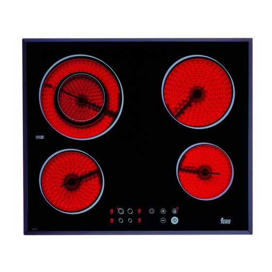
Introduction / Einführung / Présentation / Opis urz¹dzenia Model VTN DC Model VT CM 1 1,200 watt hotplate. 1 1,200 watt hotplate. 2 1,800 watt hotplate. 2 1,800 watt hotplate. 3 700/2,100 watt double circuit hotplate. 3 1,800 watt hotplate. - Page 5 Model VT DUAL.1 Model VT CM INOX HALOGEN 1 700/2,100 watt double circuit hotplate. 1 1,200 watt hotplate. 2 Semi-rapid burner 1,500 Kcal/h -1.75 kW. 2 1,800 watt halogen hotplate. 3 1200 watt hotplate. 3 1,800 watt hotplate. 4 Rapid burner 2,580 Kcal/h -3 kW. 4 1,200 watt hotplate.
- Page 6 Model VTC DC Model VTC B 1 1,200 watt hotplate. 1 1,200 watt hotplate. 2 1,800 watt hotplate. 2 1,800 watt hotplate. 3 700/2,100 watt double circuit hotplate. 3 2,100 watt hotplate. 4 1,800 watt hotplate. 4 1,200 watt hotplate. 5 Residual heat indicator lights.
- Page 7 Model VR 622 Model TT 620 1 1,500 watt hotplate. 1 1,400/2,000 watt double circuit hotplate. 2 1,400/2,000 watt double circuit hotplate. 2 1,800 watt hotplate. 3 700/2,100 watt double circuit hotplate. 3 1,200 watt hotplate. 4 1,500 watt hotplate. 4 1,500 watt hotplate.
- Page 8 Model VT TC 60.3 Model TR 620 1 1,200 watt hotplate. 1 700/2,100 watt double circuit hotplate. 2 700/1,700 watt double circuit hotplate. 2 1,800 watt hotplate. 3 1,400/2,000 watt double circuit hotplate. 3 1,500 watt hotplate. 4 1,200 watt hotplate. 4 1,200 watt hotplate.
- Page 9 Model TT 630 Models TR 640 and TT 640 1 1,800 watt hotplate. 1 700/1,700 watt double circuit hotplate. 2 1,500/2,400 watt double circuit hotplate. 2 1,800/2,700 (or 1,500/2,400 Watts, according 3 1,200 watt hotplate. to the model) watt double circuit hotplate. * Residual heat indicator.
- Page 10 Model TC 620 Model TT 600, TR 600 and TB 600 1 1,400/2,000 watt double circuit hotplate. 1 2,100 watt hotplate. 2 1,800 watt hotplate. 2 1,800 watt hotplate. 3 1,200 watt hotplate. 3 1,200 watt hotplate. 4 1,500 watt hotplate. 4 1,200 watt hotplate.
- Page 11 Model TM 620 Model TR 735 AB 1 700/2,100 watt double circuit hotplate. 1 1,800 watt hotplate. 2 1,800 watt hotplate. 2 1050 / 1,950 / 2,700 watt hotplate. 3 1,500 watt hotplate. 3 1,200 watt hotplate. 4 1,200 watt hotplate. * Residual heat indicator.
- Page 12 Model TM 601 Model TR 641 1 2,100 watt hotplate. 1 1,400/2,000 watt double circuit hotplate. 2 1,800 watt hotplate. 2 1,800 watt hotplate. 3 1,200 watt hotplate. 3 1,200 watt hotplate. 4 1,200 watt hotplate. 4 1,200 watt hotplate. * Residual heat indicator.
-
Page 13: User Guide
Likewise, any internal work on the hob should only be done by TEKA’s Before installing and using it, we would technical staff, including the change of the ask that you read this Manual carefully flexible supply cable of the appliance. -
Page 14: Installation
20, 30 and 40 mm. In the packaging of the models VTN DC and TC 620, there is a template included that is for use in sizing the space for these glass ceramic hob mo- minimun 40 mm dels. -
Page 15: Fixing The Hob
GLASS IF IT SUFFERS A VIOLENT BLOW OR IF IT IS USED IMPROPERLY. Fixing the hob VTN DC and TC 620 (see figs. 3 and 4) Rest of the models The dimensions L and W are shown in the table "Dimensions and characteris- tics"... -
Page 16: Connecting The Electricity
If the flexible supply cable fitted to the VT CM hob model ever needs to be changed, it Self-tapping screw for 20 should be replaced by TEKA’s official service. and 30 mm thick worktops Sealing joint The input cable should not be in contact ei-... -
Page 17: Model Vt Dual.1
Rear view of the Control Panel: fig. 5 fig. 6 Flexible supply cable Connector Protective box for electrical assembly If the cardan telescopic shafts are too Retention clips short, extensions can be added (not provi- Pins ded, but available as an accessory). These are added by pressing, and they are fixed by the cover that is included. -
Page 18: Gas Conversion
Information for Technical Assis- tance: whenever the type of gas or the ap- TEKA INDUSTRIAL, S.A. assumes no pliance’s pressure is changed, the new re- responsibility for any hob malfunction if the gulation plate should be placed on top of... -
Page 19: Technical Information
Technical information Dimensions and Characteristics TT 600 VT TC TR 640 TR 620 VT CM TR 735 TR 600 60.3 INOX TT 640 TM 620 Models TB 600 HALO- TM 601 Hob dimensions Height (mm) Length (mm) Width (mm) Dimensions of the placement in the unit Length (mm) (L) Width (mm) (W) Depth (mm) - Page 20 Models VTC B VT CM DUAL.1 Hob dimensions Height (mm) Length (mm) Width (mm) Dimensions of the placement in the unit Length (mm) (L) Width (mm) (W) Depth (mm) Configuration Double radiant hotplate 700/2100W circuit Double radiant hotplate 700/1700W circuit Double radiant hotplate 1400/2000W circuit 2100W radiant hotplate...
-
Page 21: Technical Details
clear, a window opened, or an effective Technical details mechical ventilation system device, such as a hood, installed. CHARACTERISTICS COMMON TO ALL The intense and prolonged use MODELS of the appliance may call for comple- mentary ventilation, such as opening a The supply voltage and frequency will be window, or more efficient ventilation as shown on the rating plate. -
Page 22: Use And Maintenance
Use and Maintenance Special requirements Model VT TC 60.3 before first use fig. 7 Before connecting the hob to the electric mains, check that the voltage and fre- quency of the mains matches what is shown on the hob’s rating plate, which is located lower down, and on the guarantee or, where appropriate, the technical datas- heet supplied, which should be kept toge-... - Page 23 Models TR 640, TT 640, TR 620, TT 620 and TM 620 fig. 9 Light indicating the hotplate's double The touch control is activated and a circuit is on (only next to double circuit pears on all the power indicators (3) and hotplates).
-
Page 24: Double Or Triple Circuit Hotplate
press) and to increase the power (touch longer exists, the indicator light will go out when the hotplate is already switched on). (if the hob is disconnected), or a will show if the hob is still connected. The power sensor needs to be touched wi- thin 5 seconds after choosing the hotplate, Switch the hotplate off before you have fi- or the hotplate will switch off and will have... -
Page 25: Locking The Hob's Sensor
4 On model TR 735 AB, if once the second (12) is lit. circuit is in operation you then wish to activate the third circuit, touch the sen- If you use the on / off sensor to turn the ap- (6) once again. -
Page 26: Safety Disconnection
locking function will be reactivated and will switch it back on again. reappear the next time the touch control is Heat-up function activated. (Automatic cooking start) Cancelling the locking function This feature enables you to set the start Locking can be permanently deactivated time for cooking. -
Page 27: Timer Function
dicator will flash on and off, alternating bet- Timer Function ween , then decrease it to power using sensor . The system will keep the hotplate at power 9 (maximum) for 2.5 mi- This feature enables you to do your cooking nutes, flashing on and off alternately bet- while you yourself are not present: The ween... - Page 28 Viewing / Changing the programmed selected hotplate (11) must be on. time 2 Touch the clock sensor (7). The deci- To view on the clock indicator (8) the time mal point for the clock (13) will come on. left before the hotplate turns off, you only have to select the hotplate required, both 3 Use the sensor (4) to decrease the...
-
Page 29: The Clock As Countdown Timer
Disconnecting the clock to set, or (4) to decrease it (from 1 to 99 minutes). You can keep your finger If you wish to stop the clock before the pro- on the sensors (7/4) to make grammed time has elapsed: the minutes pass by automatically to make your selection more quickly. -
Page 30: Power Surges
Whenever the clock is not being used in this manual, you should disconnect the conjunction with a cooking area, it can be appliance and contact TEKA's technical used as a countdown timer. To do this, you service. use the clock without selecting a hotplate. -
Page 31: Ceramic Hobs With Controls Instructions
termittent beeping will sound. One of the following messages will appear intermit- tently on the hotplates' displays *. ó * On models TR 640 and TT 640 the digit will not appear, since these models only have three power indicators for the hotplates. When normal power resumes, the beeping and the display message will cease, while fig. -
Page 32: Model Vt Dual.1
To only have the inside ring turned on, turn Model VT DUAL.1 the control knob clockwise and set it to the position you require. To turn on the whole Anti-accidental turn system hotplate, set the control to position “12” on gas controls and go on turning, gently, until it goes past “0”... -
Page 33: Suggestions On Using The Burners Effectively
fig. 12 Suggestions for using the burners effectively * Rapid burners should not be used with pans that have a small diameter, becau- se part of the flame will spread away from the pan, thus reducing performan- ce significantly. (See fig. 13) fig. -
Page 34: Cleaning And Care The Burners
inspected by specialised technical service personnel at least once every 4 years. Cleaning and care the burners Note: Any alteration or adjustment nee- * The grids should be cleaned with a non- ded by the appliance should be made by abrasive scourer when they have cooled authorised technical personne down. -
Page 35: Cleaning And Care
* Pans should be made of a material CLEANING AND CARE THE GLASS which is heat-resistent so that they do not melt on the glass. The degree of soiling should be taken into * The glass will tolerate bangs from big account when cleaning, and the items and pans that do not have sharp edges. - Page 36 Take great care when using the TEKA INDUSTRIAL S.A. reserves the right glass scraper. The blade can cause in- to alter its manuals in any way it deems ne-...
-
Page 37: If Something Doesn't Work
If something doesn’t work Before calling the Technical Service, please make the following checks: Fault Possible cause Possible solution FOR ALL THE MODELS: Neither the hotplates nor the pilot lights are working The cable is not connected Connect the cable to the to the mains mains The pan is sticking to the glass... -
Page 38: Model Vt Dual.1
Fault Possible cause Possible solution MODELS TT 620, TR 620, TR 640, TT 640, VT TC 60.3 AND TM 620: Continuous beeping, disconnection of control and symbol on displays There is an object or li- Remove the object or liquid quid covering up the that is covering the touch touch control. - Page 39 2 223 45668 Korea Republic Seoul TEKA KÜCHENTECHNIK 7620 1600 7620 1626 Malaysia Kuala Lumpur (MALAYSIA) SDN.BHD. TEKA MEXICANA S.A. de C.V. 55 5133 0493 555 762 0517 Mexico Mexico City TEKA POLSKA SP. ZO.O. 22 7383270 22 7383278 Poland Pruszkow TEKA PORTUGAL, S.A.
Need help?
Do you have a question about the VTN DC and is the answer not in the manual?
Questions and answers