Table of Contents
Advertisement
Quick Links
Advertisement
Table of Contents

Related Manuals for GST GST200


Summary of Contents for GST GST200
-
Page 2: Table Of Contents
GST200 Intelligent Fire Alarm Control Panel Installation and Operation Manual The Intelligent Solution CONTENTS Installation Precautions..................... 1 Preface EN 54 Information..................2 Chapter 1 Product Introduction ................3 Chapter 2 Technical Specifications ................4 2.1 Operating Voltage ....................4 2.2 Standby Batteries....................4 2.3 Communication Loop Parameters .............. - Page 3 GST200 Intelligent Fire Alarm Control Panel Installation and Operation Manual The Intelligent Solution 4.7 Field Device Commission ................. 19 Chapter 5 Display and Disposal of System Information ........20 5.1 Normal Information ................... 20 5.2 Fire Alarm ......................20 5.2.1 Fire Alarm Screen .................
-
Page 4: Installation Precautions
Consult with the appropriate Authority Having Jurisdiction (AHJ) for confirmation of the requirements. GST200 Fire Alarm Control Panel (FACP) shall only be installed and serviced by trained specialist. Disconnect all sources of power before servicing. Control unit and associated equipment may be damaged by removing and/or inserting cards, modules, or interconnecting cables while the unit is energized. -
Page 5: Preface En 54 Information
Output to fire alarm devices Outputs Output to automatic fire protection equipment 7.10 EN 54 The power supply of GST200 FACP complies with EN 54-4 requirements. √ AC-DC 100W Power Supply Functions EN 54-4 Clause Derive Power supply from main source... -
Page 6: Chapter 1 Product Introduction
The Intelligent Solution Chapter 1 Product Introduction GST200 Intelligent Fire Alarm Control Panel (FACP) is designed by EN 54-2 standard with qualities of simple installation, operation, and easy maintenance. It is used in fire alarm system with the following features: It controls at most 30 zones. -
Page 7: Chapter 2 Technical Specifications
Maximum Charge Capacity: 2 12V/17Ah batteries Recommended manufacturer and model of battery: Yuasa NP17-12I Recommended Wiring (subject to local installation codes): GST FireCable ® 2E/1.5 2 core and Earth 1.5mm Pirelli Cable Limited FP200 FLEX 2 core and Earth 1.5mm 2.3 Communication Loop Parameters 2.3.1... -
Page 8: Detecting Loop Parameters
Output Current: 0mA~300mA Type of Loop: Class A loop Recommended Wiring (subject to local installation codes): GST FireCable ® 2E/1.0 2 core and Earth 1mm Pirelli Cable Limited FP200 FLEX 2 core and Earth 1mm Recommended Cable Length ≤1000m 2.5 Output Loop Parameters Recommended Wiring (subject to local installation codes): GST FireCable ®... -
Page 9: Chapter 3 Structure And Configuration
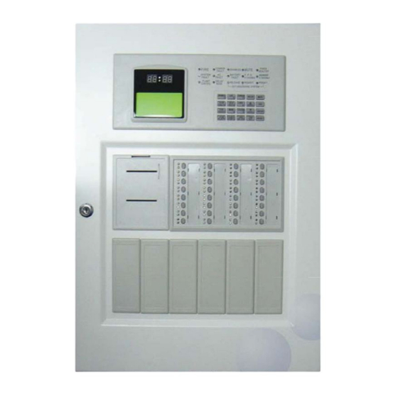
The Intelligent Solution Chapter 3 Structure and Configuration 3.1 Appearance and Internal Structure GST200 FACP is wall-mounted. Its appearance and internal structure are shown in Fig. 3-1 and 3-2. Fig. 3-1 1 Clock 2 LCD 3 Printer panel 4 Optional units... -
Page 10: Display Area
GST200 Intelligent Fire Alarm Control Panel Installation and Operation Manual The Intelligent Solution 3.1.1 Display Area The display area consists of clock, LCD, LED and keypad, which are shown in Fig. 3-3. Fig. 3-3 3.1.2 Description of LEDs FIRE: Red. It illuminates when the FACP detects an alarm condition of connected detectors. -
Page 11: Description Of Keys
GST200 Intelligent Fire Alarm Control Panel Installation and Operation Manual The Intelligent Solution PLANT CONTROL: Yellow. Action message indication. It illuminates when there are feedback signals from fire-protective plant. DELAY MODE: Yellow, it illuminates when the output is set in delay mode. -
Page 12: Zone Indication And Manual Interventional Panel (Zcp)
GST200 Intelligent Fire Alarm Control Panel Installation and Operation Manual The Intelligent Solution make the clock display change between month/day mode and hour/minute mode. VIEW PLANT: Viewing action messages. 3.1.4 Zone Indication and Manual Interventional Panel (ZCP) Appearance of zone indication and manual intervention panel is shown in Fig. 3-4. -
Page 13: Configuration
Greek letters, block symbol etc.), and 16 code characters (6×7 dot) which can be defined by the user through program, and replace any code font by commanding, so as to print characters of different language. Communication card GST200 Intelligent Fire Alarm Control Panel (FACP) provides a multi-functional Page 10... -
Page 14: Periphery Devices
5 20P data cable connecting with main board. 6 Standard RS-232 interface connecting with GMC. Note: You need to include a RS-232 card in your first order of GST200. Only with this card, device definition and C&E equations can be downloaded from PC. -
Page 15: Loop Isolator
3.3.4 Manual Call Points A series of manual call point (such as I-9202) can be connected to the loop of GST200. When fire is confirmed manually, press the glass on the MCP, alarm signal can be sent to the FACP. After receiving the alarm signal, the FACP will show the number and location of the MCP, and sound alarm. -
Page 16: Chapter 4 Installation
Power up the FACP and carry out start-up inspection. Connect field devices. Inspect circuits and register devices. Define devices and C&E equations using GST-DEF software on a PC and download them to the FACP through definition software according to engineering configuration. -
Page 17: Start-Up Check
4.4 Connections of Field Devices 4.4.1 Connection of AC Power GST200 Fire Alarm Control Panel receives power from a 230V, 50Hz supply. The current flows through a filter to the transformer. The transformer converts the input mains voltage to 27VAC. -
Page 18: Connection Of Batteries
Caution: Do not connect power to your device until you have completed all input and output connections. Failure to do so may result in injury! GST200 connects with field devices by loop interface board. Terminals of loop interface board are shown in Fig. 4-3. - Page 19 GST200 Intelligent Fire Alarm Control Panel Installation and Operation Manual The Intelligent Solution Description: CLASS CHANGE (XT3): Shorting this terminal can make Sounder Circuit Output (XT7) output. FAULT OUTPUT (XT8): Fault relay is closed in normal condition, and it’s disconnected in fault condition.
- Page 20 GST200 Intelligent Fire Alarm Control Panel Installation and Operation Manual The Intelligent Solution Diode Diode End-of-line SOUNDER CIRCUIT Resistor 4.7kΩ Sounder Sounder OUTPUT (XT7) Fig. 4-4 A 4.7kΩ resistor is connected at the SOUNDER CIRCUIT OUTPUT (XT7) as factory default. Please remove it and keep it well before connection. Connect the loop in correct polarity and add the resistor to the end of the line.
-
Page 21: Connection Inspection And Device Registration
GST200 Intelligent Fire Alarm Control Panel Installation and Operation Manual The Intelligent Solution connection. The maximum current of the circuit depends on the number of fire supervisory device. Do not overload. Connection of Class A Loop A Class A loop is shown in Fig. 4-7. -
Page 22: Device Registration
GST200 Intelligent Fire Alarm Control Panel Installation and Operation Manual The Intelligent Solution 4.5.2 Device Registration Press SYSTEM and input commission password. Then press ENTER to go to system setting menu. Then press ESC to exit system setting menu, the system enters commission state (there will be a “-“... -
Page 23: Chapter 5 Display And Disposal Of System Information
The Intelligent Solution Chapter 5 Display and Disposal of System Information GST200 can be started after installation according to description in Chapter 4. Turn on the power supply, and main and standby power switch on the FACP, the FACP executes self-test and enter normal standby state. -
Page 24: Disposal Of Fire Alarm Signal
GST200 Intelligent Fire Alarm Control Panel Installation and Operation Manual The Intelligent Solution 001 0f 003 !FIRE! 05:25 Zone:001-Z-001 Device-30 ------------------------------------- Last !Fire! Zone:003 Z-003 Device-061 Fig. 5-3 001 0f 003 !FIRE! 05:25 // There are fire alarms in three zones and this is the first. -
Page 25: Fault
GST200 Intelligent Fire Alarm Control Panel Installation and Operation Manual The Intelligent Solution Step 1: Evacuate the people in field. Step 2: Call the fire department. Step 3: Initiate extinguishers. If it is a false alarm, please take the following measures. - Page 26 GST200 Intelligent Fire Alarm Control Panel Installation and Operation Manual The Intelligent Solution Keypad fault: The panel reports keypad fault if its keypad circuit is in fault: It lights the COMMON FAULT and SYSTEM FAULT LED. The LCD displays “Key fault”.
-
Page 27: Disposal Of Fault Message
GST200 Intelligent Fire Alarm Control Panel Installation and Operation Manual The Intelligent Solution 001 0f 004 FAULT10:18 // There are four devices reporting fault, and this is the first fault message. Zone:003-011Optical // The number the zone with the fault message, the address and type of the device with the fault message. -
Page 28: Chapter 6 Description Of System Operation
GST200 Intelligent Fire Alarm Control Panel Installation and Operation Manual The Intelligent Solution Chapter 6 Description of System Operation 6.1 Keypad 6.1.1 Keypad Functions Most of the keys have double functions. Lower mark is a character and upper mark is a command that is only activated in monitoring state. -
Page 29: User Operation Instruction (No Password Requirement)
GST200 Intelligent Fire Alarm Control Panel Installation and Operation Manual The Intelligent Solution GST CO., LTD. Press ENTER confirm Fig. 6-2 6.2 User Operation Instruction (No Password Requirement) 6.2.1 Changing time display The clock is usually displayed in hour and minute. In normal monitoring state, pressing ENTER, month and date are displayed. - Page 30 GST200 Intelligent Fire Alarm Control Panel Installation and Operation Manual The Intelligent Solution GST CO., LTD. *LCD Contrast* Fig. 6-4 Input number 2, you can enter the screen for setting browse mode, as shown in Fig. 6-5. 1 is for zone mode, and 2 is for loop mode.
- Page 31 GST200 Intelligent Fire Alarm Control Panel Installation and Operation Manual The Intelligent Solution A condition is composed of the following items: G(S) 01 001 03 ice type Device add ress/Quantity of events defined in special condition Zone number of the device...
- Page 32 GST200 Intelligent Fire Alarm Control Panel Installation and Operation Manual The Intelligent Solution Browse 03 Zone (012) Zone:01 Sum:004 ENTER Zone:02 Sum:004 Zone:03 Sum:004 Browse Zone: 01 Sum: 004 ENTER NO.001 Optical NO.002 Optical NO.003 Optical Browse NO.004 Sounder Zone: 01 office1 NO.001 Optical...
- Page 33 GST200 Intelligent Fire Alarm Control Panel Installation and Operation Manual The Intelligent Solution Office1 // Description of the device position. Input number 2, you can view FACPs and repeater panels in network. Input number 3, you can view definitions to ZCP keys as in Fig. 6-10.
- Page 34 GST200 Intelligent Fire Alarm Control Panel Installation and Operation Manual The Intelligent Solution 6.2.2.7 Browsing disable messages You can view disable messages by pressing VIEW DISABLE when the screen is displaying non-disable messages. The screen of loop mode is shown in Fig. 6-12 and the screen for zone mode is shown in Fig.
-
Page 35: Silencing The Panel
GST200 Intelligent Fire Alarm Control Panel Installation and Operation Manual The Intelligent Solution 002 of 002 Disable 12:01 // There are devices from 2 zones that are disabled, and this is the second zone. Zone: 006-Z-006 // Zone number and description message of the disabled zone. -
Page 36: Enable And Disable
GST200 Intelligent Fire Alarm Control Panel Installation and Operation Manual The Intelligent Solution n fire alarm condition, the system needs to be silenced before RESET operation. 6.3.2 Enable and Disable The disabling/enabling of devices is mainly used when a trouble condition of a device cannot be removed in time. - Page 37 GST200 Intelligent Fire Alarm Control Panel Installation and Operation Manual The Intelligent Solution In order to disable all devices with type number 001~11 of Zone No.1, you need to input in sequence the zone number 001, device code *** and device type **.
-
Page 38: Operation Through Star/Stop Key
GST200 Intelligent Fire Alarm Control Panel Installation and Operation Manual The Intelligent Solution Selecting number 1 will disable all delay settings in the system. Selecting number 2 will enable system to output according to the edited delay time, and light the DISABLE and DELAY MODE LED. Pressing VIEW DISABLE, the LCD will display “immediate actioning of outputs is disabled”. -
Page 39: Operation Of The Devices By Zcp
GST200 Intelligent Fire Alarm Control Panel Installation and Operation Manual The Intelligent Solution 6.3.3.3 Viewing Devices being Started In the screen shown in Fig. 6-20, you can view the started devices by entering number “3” followed by ENTER, as shown in Fig. 6-23. -
Page 40: Setting Work Mode Of Printer
GST200 Intelligent Fire Alarm Control Panel Installation and Operation Manual The Intelligent Solution 6.3.5 Setting work mode of printer Press PRINT to enter print mode as shown in Fig. 6-25. *Print Mode* 1 Disable 2 Only Fire 3 All History Fig 6-25 Entering “1”, printing will be disabled. -
Page 41: Instructions For System Administrator (Manager Password Required)
GST200 Intelligent Fire Alarm Control Panel Installation and Operation Manual The Intelligent Solution *Burglar Mode* 1 Disable 2 Enable 3 Only Night Fig. 6-27 If “1” is input, burglar mode is disabled. The system doesn’t respond to the action of security modules. -
Page 42: Modifying System Time
GST200 Intelligent Fire Alarm Control Panel Installation and Operation Manual The Intelligent Solution 6.4.1 Modifying System Time Inputting “1” in the screen of Fig. 6-29, the system enters Time/Date setting screen. See Fig. 6-30. After inputting time on highlighted position and press TAB, then next data is highlighted. -
Page 43: Network Setup
GST200 Intelligent Fire Alarm Control Panel Installation and Operation Manual The Intelligent Solution Modify Password Confirm Password ******** Fig. 6-33 Input password again, if the two passwords are the same, the LCD will display the window shown in Fig. 6-34, meaning the modification is successful. -
Page 44: Setting Up Beginning Zone Number
GST200 Intelligent Fire Alarm Control Panel Installation and Operation Manual The Intelligent Solution You can set the panel to display network message or not by entering number 2, as shown in Fig. 6-37. *Display Mode* 1 Disable 2 Enable Fig. 6-37 6.4.4... - Page 45 GST200 Intelligent Fire Alarm Control Panel Installation and Operation Manual The Intelligent Solution * Outputs Setup * 1. Default Outputs 2. C&E Outputs Fig. 6-40 6.4.5.1.1 Default Outputs Entering number 1 in the screen in Fig. 6-40 will choose “1. Default Outputs” to set the SOUNDER CIRCUIT OUTPUT (hereinafter referred to as Sounder A) and F.P.E...
-
Page 46: Initialization Of System
GST200 Intelligent Fire Alarm Control Panel Installation and Operation Manual The Intelligent Solution sounders. Inputting number 2, the sounder will not be able to be silenced within 3 minutes after the first fire alarm. 6.4.5.3 Disabling Password Inputting number 3 will enter the screen for disabling password, as in Fig. 6-42. -
Page 47: Chapter 7 Standby Battery Calculations
GST200 Intelligent Fire Alarm Control Panel Installation and Operation Manual The Intelligent Solution Chapter 7 Standby Battery Calculations Equation for calculating the battery capacity: Battery capacity(Ah)=I ×T ) ×T Qmax Qmin Lmax Fout In which: =0.6A, which is the quiescent current when the FACP is full-loaded;... -
Page 48: Chapter 8 Maintenance
GST200 Intelligent Fire Alarm Control Panel Installation and Operation Manual The Intelligent Solution Chapter 8 Maintenance The FACP shall only be repaired by specially trained GST technical service personnel. Please disconnect the power before repair! 8.1 Replacing the Battery Type of battery: Sealed lead-acid battery Recommended period for replacing the battery: 5 years (25℃) - Page 49 GST200 Intelligent Fire Alarm Control Panel Installation and Operation Manual The Intelligent Solution Table 8-2 Problems Possible Causes Solutions No indication on a. AC input fuse blown Replace fuse. the panel or b. Power is abnormal Check and replace abnormal low-voltage switch power.
-
Page 50: Appendix 1 Internal Connection Diagram
GST200 Intelligent Fire Alarm Control Panel Installation and Operation Manual The Intelligent Solution Appendix 1 Internal Connection Diagram Connecting with the cabinet 1 Main Board 2 Switch Board 3 LCD 4 Printer 5 Speaker 6 Loop Interface Board 7 Power Board... -
Page 51: Appendix 2 Device Type List
GST200 Intelligent Fire Alarm Control Panel Installation and Operation Manual The Intelligent Solution Appendix 2 Device Type List NoDefine Undefined Ionization detector R+F.Heat' Rate of rise and fixed temperature detector Optical Photoelectrical smoke detector Fix Temp Fixed temperature detector Gas Det... - Page 52 GST200 Intelligent Fire Alarm Control Panel Installation and Operation Manual The Intelligent Solution SUPERV Supervisory Gas Dump Gas start-up GasAbort Gas stop Net Unit Net unit Repeater Repeater panel Gen I/P Gate valve DryPower Dry powder fire extinguisher FoamPump Foam pump...
-
Page 53: Appendix 3 Operation Menu
GST200 Intelligent Fire Alarm Control Panel Installation and Operation Manual The Intelligent Solution Appendix 3 Operation Menu Menu BROWSE To look through equipment Active EQ Loop equipment COM EQ Communication equipment, including repeater panels and slave FACPs Access ZCP LOG To view history record... - Page 54 GST200 Intelligent Fire Alarm Control Panel Installation and Operation Manual The Intelligent Solution Password Change Setting password Network Setup Setting network address Zone Start Number Setting beginning number of zones Customize Outputs Setup Default Outputs Automatically starting zonal sounders, SOUNDER CIRCUIT OUTPUT and F.P.E...
- Page 55 Only Night Burglar mode is only effective during night. The screen shows a request for on and off time. RESET Reset GST200 to normal monitoring state from fire alarm or fault state [password required] Page 52...
- Page 56 GST China Gulf Security Technology Co., Ltd. No. 80, Changjiang East Road, QETDZ, Qinhuangdao, Hebei, P. R. China 066004 Tel: +86 (0) 335 8502528 Fax: +86 (0) 335 8508942 Email: sales@gst.com.cn www.gst.com.cn GST UK Global System Technology PLC Lion Court, Staunton Harold Hall,...
Need help?
Do you have a question about the GST200 and is the answer not in the manual?
Questions and answers