Table of Contents
Advertisement
Quick Links
Download this manual
See also:
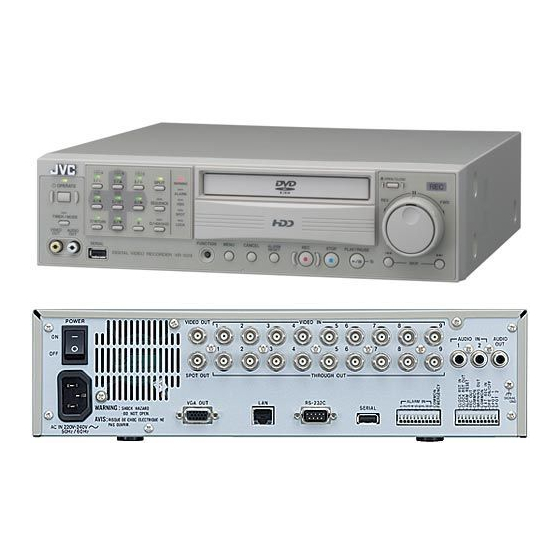
Instruction Manual
DIGITAL VIDEO RECORDER
VR-509E
OPERATE
TIMER/MODE
RETURN
VIDEO
AUDIO
OUT
OUT
SERIAL
Please read the following before getting started:
Thank you for purchasing this JVC product.
Before operating this unit, please read the instructions
carefully to ensure the best possible performance.
Set the "TIME ZONE" before operating this unit.
For the setting method, refer to 'Setting up Areas'
on page 18.
This instruction manual is made from 100% recycled paper.
SPLIT
WARNING
ALARM
SET
HDD
SEQUENCE
SPOT
LOCK
FUNCTION
INSTRUCTIONS
ALARM
MENU
CANCEL
REC/STOP
PLAY STOP
RESET
OPEN/CLOSE
REC
REW
FF
PLAY/PAUSE
SKIP
LLT0094-001A
Advertisement
Table of Contents
Troubleshooting

Related Manuals for JVC VR-509E


Summary of Contents for JVC VR-509E
-
Page 1: Digital Video Recorder
VIDEO AUDIO SERIAL Please read the following before getting started: Thank you for purchasing this JVC product. Before operating this unit, please read the instructions carefully to ensure the best possible performance. Set the “TIME ZONE” before operating this unit. -
Page 2: Safety Precautions
SAFETY PRECAUTIONS Warning Notice FOR YOUR SAFETY (Australia) 1.Insert this plug only into effectively earthed threepin power outlet. 2.If any doubt exists regarding the earthing, consult a qualified electrician. 3.Extension cord, if used, must be three-core correctly wired. IMPORTANT (In the United Kingdom) Mains Supply (AC 230 V) WARNING - THIS APPARATUS MUST BE EARTHED... - Page 3 Penalties may be applicable for incorrect disposal of this waste, in accordance with national legislation. (Business users) If you wish to dispose of this product, please visit our web page www.jvc-europe.com to obtain information about the take-back of the product.
-
Page 4: Table Of Contents
Contents SAFETY PRECAUTIONS... 2 Getting Started Main Features ... 7 How to Read this Manual ... 7 Setting/Canceling the Operation Lock ... 7 PRECAUTIONS ... 8 Part Names and Functions (Front Panel) ... 10 Part Names and Functions (Rear Panel)... 12 Part Names and Functions (Signal I/O Terminals) ... - Page 5 Useful Features Using a PC Changing the Onscreen Display Position ... 46 Setting Camera Title... 47 Setting OPERATION LOCK ... 48 Buzzer Setup ... 49 REAR TERMINAL ... 49 Hard Disk Maintenance ... 50 AUTO SCAN DISK ... 50 MANUAL SCAN DISK ... 50 DEFRAG DATABASE ...
- Page 6 Contents Changing VR-509 Settings Using a PC MONITOR OUT ... 83 INDICATION... 83 AUTO CHANGE ... 83 DIVISION PIC... 83 COVERT CHANNEL ... 84 REC DETAIL ... 84 REC PATTERN ... 84 ALARM REC ... 84 OPERATION ... 85 AUDIO OUT ... 85 ALARM TERMINAL ...
-
Page 7: Getting Started
Getting Started Main Features Built-in hard disk drive with a high capacity of 320 Simultaneous recording of 100 images / sec in 9 channels Recording up to 100 images/second. Simultaneous Playback mode Playback, jog/shuttle playback and skip play are possible during recording. -
Page 8: Precautions
Replacement is recommended after 10000 hours of use (if use in a 25°C environment). For information on maintenance planning and costs, consult your nearest JVC dealer. If a power failure occurs during formatting of hard disk, disconnection, or when configuring... - Page 9 Handling the unit • Please do not place heavy objects on the DVR, like a monitor or TV. Also, do not stack the VR-509E units on top of each other. • Please do not block the ventilation openings. • Avoid violent shocks to the unit. Do not drop the unit.
-
Page 10: Part Names And Functions (Front Panel)
Getting Started Part Names and Functions (Front Panel) OPERATE TIMER/MODE VIDEO AUDIO [OPERATE] Button and Operate LED Switches the main power on or off. The LED is illuminated when the OPERATE button is set to ON. (Page 16) [TIMER/MODE] Button When the [TIMER/MODE (REC PATTERN)] setting on the [REC DETAIL] screen is set, the following is performed. - Page 11 Part Names and Functions (Front Panel) (continued) OPERATE TIMER/MODE RETURN VIDEO AUDIO SERIAL [HDD(DVD)/0] HDD ⇔ DVD Button and LED Press this button to switch operations between DVD and HDD. The LED is illuminated when in DVD operations. [0] Button Sets the value to 0.
-
Page 12: Part Names And Functions (Rear Panel)
Getting Started Part Names and Functions (Rear Panel) WARNING: AVIS: RISQUE DE CHOC ELECTRIQUE-NE PAS OUVRIR AC IN 220V - 240V 50Hz/60Hz Power Switch Switches the power on or off. The OPERATE ON mode is automatically activated when the power is switched on. (Page 16) Make sure the system has been set in the OPERATE OFF mode before switching off the power supply. -
Page 13: Part Names And Functions (Signal I/O Terminals)
Part Names and Functions (Signal I/O Terminals) WARNING: SHOCK HAZARD -DO NOT OPEN AVIS: RISQUE DE CHOC ELECTRIQUE-NE PAS OUVRIR AC IN 220V - 240V 50Hz/60Hz [ALARM IN 1 to 9] Terminals 1 - 9 ALARM REC is activated when signals are input to these terminals. - Page 14 Getting Started Part Names and Functions (Signal I/O Terminals) (continued) Terminal [ALARM IN] Alarm Input [EMERGENCY] Emergency Input [EXT REC IN] External Record Input [CLOCK RST IN] Clock Reset Input [CLOCK RST OUT] Clock Reset Output [ALARM RESET] Alarm Reset Input [REC OUT] Record Status Output [WARNING OUT]...
-
Page 15: Installation And Preparation
Installation and Preparation System Connection (When connecting 9 Cameras) Connection with up to 9 cameras is possible with VR-509’s switcher. <Example> • Perform recording/playback by connecting to 9 cameras. • Checking recorded images at Monitor. • Execution of alarm recording upon detecting alarm signals. Camera 1 Camera 2 Camera 9... -
Page 16: Turning On/Off The Power
Installation and Preparation Turning On/Off the Power Switching the Power On 1. Connect the Power Cable. • Connect using the power cable supplied to an AC 220 V - 240 V 50Hz/60Hz outlet. 2. Switch on the power switch on the rear panel. •... -
Page 17: Menu Screen Operations
MENU Screen Operations Displaying the MENU Screen 1. Press the [MENU] button. • The MENU screen will be displayed. * Press the [MENU] once again to close the MENU screen. INTRODUCTION SET DETAIL REC DETAIL OPERATION LIVE PICTURE Button operation explanation SET UP CURSOR UPDATE/NEXT... -
Page 18: Setting Up Areas
Installation and Preparation Setting up Areas 1. Press the [MENU] button. • Opens the menus in accordance with the instructions provided in MENU Screen Operations (page 17) in the sequence of “MENU” → “DETAIL OPERATION” → “MAINTENANCE” → “AREA SELECT”. AREA SELECT LANGUAGE TIME DISPLAY FORM... -
Page 19: Setting The Date/Time
The clock reset signal is output in accordance with the following timing: • When the recorder’s internal clock reaches 00:00 or 12:00. • It is possible to align the clock with two or more VR-509E units in calibrations of seconds. MEMO •... -
Page 20: Installation Settings
Installation and Preparation Installation Settings 1. Press the [MENU] button. INTRODUCTION SET DETAIL REC DETAIL OPERATION LIVE PICTURE Button operation explanation SET UP CURSOR UPDATE/NEXT BACK FUNCTION : USER GUIDANCE • Opens the menus in accordance with the instructions provided in MENU Screen Operations (page 17) in the sequence of “MENU”... - Page 21 Installation Settings (continued) 6. Press the [SET] button. • The recording settings for the standard mode set on the “INTRODUCTION SET - 1” and “INTRODUCTION SET - 2” screens will be automatically set, and the “INTRODUCTION SET - 3” screen will be displayed. INTRODUCTION SET-3 NORMAL REC ALARM REC...
-
Page 22: Viewing Live Camera Images
Viewing Live Camera Images Switching between Display Screens The VR-509 enables images to be viewed on single screens, split screens, and sequential screens. * It is not possible to change the sequential display when the playback screen is being displayed. Automatic Single Screen Switching [SEQUENTIAL]... -
Page 23: Changing The Layout Of The Split Screens
Changing the Layout of the Split Screens 1. Press the [MENU] button. • Opens the menus in accordance with the instructions provided in MENU Screen Operations (page 17) in the sequence of “MENU” → “LIVE PICTURE”. • The layout pattern that is set is displayed at the center of the screen. -
Page 24: Setting Up Monitor Output
Viewing Live Camera Images Setting up monitor output 1. Press the [MENU] button. • The [MENU] → [DETAIL OPERATION] → [MONITOR] screens will be displayed in this sequence in accordance with the [MENU Screen Operations] explained on page 17. MONITOR BORDER COLOR LIGHTGRAY AUTO CHANGE .. -
Page 25: Split Picture
SPLIT PICTURE Sets whether or not to display each screen with automatic switching when in the split picture mode. 1. Press the [MENU] button. • The [MENU] → [DETAIL OPERATION] → [MONITOR] → [SPLIT SCREEN] screens will be displayed in this sequence in accordance with the [MENU Screen Operations] explained on page 17. -
Page 26: Viewing Live Images With Spot Output
Viewing Live Camera Images Viewing Live Images with SPOT Output It is possible to view live images with the SPOT output function. The following two methods for changing the display contents for SPOT output are available: • Changing SPOT output manually. •... -
Page 27: Covert Channel
COVERT CHANNEL Sets whether or not the screen is to be displayed in black without the camera inputs being displayed. 1. Press the [MENU] button. • The [MENU] → [DETAIL OPERATION] → [MONITOR] → [COVERT CHANNEL] screens will be displayed in this sequence in accordance with the [MENU Screen Operations] explained on page 17. -
Page 28: Recording Camera Images
Recording Camera Images Types of Recording Normal Recording The normal recording mode is operated as follows in accordance with the [TIMER/MODE (REC PATTERN)] setting made on the [DETAIL REC] screen (See page 30), and the ON/ OFF setting for the [TIMER/MODE]. Table #1: Normal Recording Mode TIMER/MODE (REC PATTERN) PROGRAM... -
Page 29: Making Normal Recordings
Making Normal Recordings STANDARD MODE 1. Set up the DETAIL REC parameters. (See page 30) 2. Set the normal recording parameters with [STANDARD MODE]. (See page 31) 3. Check to confirm that the LED for TIMER/MODE is extinguished. Press the [REC/STOP] button. •... -
Page 30: Setting Up The Detail Rec
Recording Camera Images Setting up the DETAIL REC 1. Press the [MENU] button. • Opens the menus in accordance with the instructions provided in MENU Screen Operations (page 17) in the sequence of “MENU” → “DETAIL REC”. DETAIL REC OPERATION SET .. NOMALLY AUDIO REC ALARM AUDIO REC ALARM TERMINAL .. -
Page 31: Setting The Operation Set
Setting the Operation Set 1. Press the [MENU] button. • Opens the menus in accordance with the instructions provided in MENU Screen Operations (page 17) in the sequence of “MENU” → “DETAIL OPERATION” → “OPERATION SET”. OPERATION SET STANDARD .. REC PATTERN1 .. -
Page 32: Operation Setup (Recovery Rec, Rec Indicator, Repeat Rec)
Recording Camera Images Setting the Operation Set (continued) Procedure for Changing the Number of Cameras 1. Take a note of all the [OPERATION SET] data settings (F.RATE, QLY and M.DET on NORMAL REC/ALARM REC) when [STANDARD] or [REC PATTERN 1 to 9] is in use. -
Page 33: Alarm Recording
ALARM Recording Alarm recording is started when signals are input and when motion is detected in the STOP mode, and during normal recording and timer recording. Emergency Recording 1. Connect the [EMERGENCY] terminal to the alarm device. 2. Setting the [DETAIL REC] screen. (Page 30) Set the [EMERGENCY REC] setting to anything other than “OFF”. -
Page 34: Setting Alarm Recording
Recording Camera Images Setting ALARM Recording 1. Press the [MENU] button. • The [MENU] → [REC DETAIL] → [ALARM REC] screens will be displayed in this sequence in accordance with the [MENU Screen Operations] explained on page 17. ALARM REC CAM NO DURATION 3MIN... -
Page 35: Using The Motion Detection Function
Using the Motion Detection Function There are two methods of performing motion detection: 1) with a pre-determined set of parameters, and 2) by freely setting detection sensitivity. It is also possible to set the area for which detection is to be carried out on the screen. * Motion detection is not possible when operations are being carried out on the menu. -
Page 36: Motion Detection With Freely Determined Sensitivity Levels
Recording Camera Images Motion Detection with Freely Determined Sensitivity Levels When the [Motion Detection] value on the [OPERATION SET] screen is set at [USER], it is possible to set the sensitivity for [DYNAMIC SENSITIVITY LEVEL], [TARGET AREA LEVEL] and [STOP LEVEL]. These settings have no effect if anything other than [USER] has been specified. -
Page 37: Setting Up The Motion Detect Area Set
Setting up the MOTION DETECT AREA SET Sets up the area for motion detection. This setting is applicable for when both [USER] and any other parameter has been selected for the sensitivity level. 1. Press the [MENU] button. • The [MENU] → [REC DETAIL] → [ALARM REC] screens will be displayed in this sequence in accordance with the [MENU Screen Operations] explained on page 17. -
Page 38: Weekly Timer
Recording Camera Images WEEKLY TIMER 1. Press the [MENU] button. • Opens the menus in accordance with the instructions provided in MENU Screen Operations (page 17) in the sequence of “MENU” → “DETAIL REC” → “WEEKLY TIMER”. WEEKLY TIMER START MODE EXEC SUN * * : * *... -
Page 39: Date Timer
DATE TIMER 1. Press the [MENU] button. • Opens the menus in accordance with the instructions provided in MENU Screen Operations (page 17) in the sequence of “MENU” → “DETAIL REC” → “DATE TIMER”. DATE TIMER START MODE EXEC * * : * * * * : * * * * * * 1. -
Page 40: Playing Back Recorded Images
• In order to ensure that the hard disk is kept in its optimal status, the VR-509E will periodically enter the maintenance mode automatically. When maintenance is in progress there are cases where the audio sound may break up or the images be displayed after a delay during playback. -
Page 41: Switching Between Playback Screens
Switching between Playback Screens The VR-509 is equipped with features to playback images on single screens and split screens. * Sequential display is not possible during playback. CH1 CH2 Single Screen CH3 CH4 [SPLIT] CH1-9 [SPLIT] Single Screen • The SPLIT display LED and the SEQUENCE display LED are both extinguished. -
Page 42: Searching With The Alarm List
Playing Back Recorded Images Searching with the Alarm List 1. Press the [PLAY/PAUSE] button. • The “EVENT SEARCH” screen will be displayed. EVENT SERCH CONTINUOUS PLAYBACK ALARM LIST SEARCH .. SEARCH DATE * * / * * / 2 0 * * * * : * * SKIP SET .. -
Page 43: Searching For Images According To Date/Time
Searching for Images According to Date/ Time 1. Press the [PLAY/PAUSE] button. • The “EVENT SEARCH” screen will be displayed. EVENT SERCH CONTINUOUS PLAYBACK ALARM LIST SEARCH .. SEARCH DATE * * / * * / 2 0 * * * * : * * SKIP SET .. -
Page 44: Skipping Recorded Images
Playing Back Recorded Images Skipping Recorded Images 1. Press the [PLAY/PAUSE] button. • The “EVENT SEARCH” screen will be displayed. EVENT SERCH CONTINUOUS PLAYBACK ALARM LIST SEARCH .. SEARCH DATE * * / * * / 2 0 * * * * : * * SKIP SET .. -
Page 45: Enlarging Images (Image Zoom)
Enlarging Images (Image Zoom) Images can be viewed in an enlarged mode. Only single-screen displays can be enlarged. * Enlarged displays are not possible when live images are being displayed. 1. Start playback (See page 40 “Playing Back Images”) 2. Press buttons [1] to [9] to select the camera input that is to be enlarged. -
Page 46: Useful Features Using A Pc
Useful Features Using a PC Changing the Onscreen Display Position As can be seen in the illustrations below, the VR-509’s DATE/ TIME, camera title and other elements can be displayed on the monitor screen. It is also possible to change their position on the screen. -
Page 47: Setting Camera Title
Setting Camera Title 1. Press the [MENU] button. • Opens the menus in accordance with the instructions provided in Changing MENU Settings (page 17) in the sequence of “MENU” → “DETAIL OPERATION” → “MONITOR” → “CAMERA TITLE”. CAMERA TITLE CAM1: ALPHANUMERIC * * * * * * * * * * * * * * * * * * * * * * * * * * * * * * * *... -
Page 48: Setting Operation Lock
Useful Features Using a PC Setting OPERATION LOCK 1. Press the [MENU] button. • Opens the menus in accordance with the instructions provided in Changing MENU Settings (page 17) in the sequence of “MENU” → “DETAIL OPERATION” → “ONSCREEN/OPERATION” → “OPERATION”. OPERATION RECOVERY REC REC INDICATOR... -
Page 49: Buzzer Setup
Buzzer Setup 1. Press the [MENU] button. • The [MENU] → [DETAIL OPERATION] → [Display/ Operation] → [BUZZER] screens will be displayed in this sequence in accordance with the [MENU Screen Operations] explained on page 17. BUZZER ALARM HDD FULL WARNING VIDEO LOSS HDD ERROR... -
Page 50: Hard Disk Maintenance
Useful Features Using a PC Hard Disk Maintenance When a power failure occurs while in the Recording mode or Alarm Record Standby mode, or when a failure occurs in the recorded data on the hard disk, recording/playback may not function properly. To repair the hard disk, two types of scan disk functions are available on the VR-509: AUTO SCAN DISK Scans the hard disk automatically when the power is switched... -
Page 51: Defrag Database
DEFRAG DATABASE When alarm recording is performed repeatedly with Repeat Recording set to “ALL” or “ALARM LOCK”, data in the hard disk may become fragmented. Continued use of such data may cause files to split up and be recorded into free space, thereby giving rise to fragmentation or decay of data, which subsequently slows down the speed dramatically during hard disk searches. -
Page 52: Setting Up The Hard Disk For Mirroring
Useful Features Using a PC Setting up the Hard Disk for Mirroring Mirroring refers to recording the same data in the 2 built-in hard disks. In this way, recorded data can be secured even if data on one of the hard disks is damaged. (See on page 53 for the notes on “Setting up MIRRORING”) Setting up MIRRORING 1. -
Page 53: Deleting Alarm Lists
Setting up the Hard Disk for Mirroring (continued) Precautions When Setting up Mirroring • The capacity of the hard disk will be reduced by approximately half when mirroring is set up. It is therefore necessary to take care when setting recording times. •... -
Page 54: Pass Code Setup
Useful Features Using a PC Pass Code Setup 1. Press the [MENU] button. • The [MENU] → [DETAIL OPERATION] → [MAINTENANCE] → [PASSCODE SET] screens will be displayed in this sequence in accordance with the [MENU Screen Operations] explained on page 17. PASSCODE SET PASSCODE NONE... -
Page 55: Rebooting The System
Rebooting the System 1. Press the [MENU] button. • The [MENU] → [DETAIL OPERATION] → [MAINTENANCE] → [MAINTENANCE/LOG] screens will be displayed in this sequence in accordance with the [MENU Screen Operations] explained on page 17. MAINTENANCE/LOG TOTAL TIME ********** h POWER OUTAGE TIME LIST PL - **** **/**/**... -
Page 56: Using Dvd
DVD-R/RW discs, although playback performance is not guaranteed. They cannot be played back on the VR-509. Consult with your nearest JVC dealer for details on suitable DVD players. (See Export Format on page 57) * DVD video discs available on the open market cannot be played back. -
Page 57: Exporting Data On Dvd
Exporting Data on DVD The VR-509 is equipped with a function to enable the images stored on the hard disk to be exported to DVDs. * It is possible to export images to a DVD when recording onto the hard disk. 1. - Page 58 Using DVD Exporting Data on DVD (continued) 6. Setting up the [DURATION] setup screen. Starting time Ending time DURATION 2005 / 10 / 01 10 : 01 2005 / 10 / 01 10 : 59 INPUT : 01 TYPE : ALL 2000MB [99] DEL 02 2005 / 10 / 01 10 : 01 2005 / 10 / 01 10 : 59...
- Page 59 DVD, and then execute the [CHECK] or [EXPORT] functions once again. *1: As the VR-509E exports data for which the frame rate has been converted as different alarm recorded data when frame rates are changed in accordance with the...
-
Page 60: Playing Back Exported Images On Dvd
Using DVD Playing Back Exported Images on DVD It is possible to playback the images that have been exported from the hard disk to DVDs. Set the export format to format including “SELF-PLAYING” when exporting the data. * DVD images can be played back when recording onto the HDD. -
Page 61: Dvd-Video Format Menus And Playback
DVD-Video Format Menus and Playback The following title menus and chapter menus are created for DVDs that are formatted in the DVD-Video and DVD-Video (intermittent interpolation) formats for exporting purposes. * DVDs that are created in the DVD-Video and DVD-Video (intermittent interpolation) cannot be played back on the VR- 509E. -
Page 62: Using Other External Devices
* Contact your nearest JVC dealer for details on the flash memories that can be used. on October 26th 2005 from camera 9 in the normal recording mode. -
Page 63: Storing Set Data In The Flash Memory
* Image distribution onto a network will be suspended when setup data is being downloaded or uploaded. * Contact your nearest JVC dealer for details on the flash memories that can be used. The name of the setting data file (Example) E00-12_051012040750.509. -
Page 64: External Hard Disk Drives
VR-509 and connect it to a personal computer in order to view the images. * Consult with your nearest JVC dealer for details on the external hard disks that can be used. * It is recommended that a UPS is used to ensure system safety. -
Page 65: Connecting To A Pc
AC IN 220V - 240V 50Hz/60Hz Connecting to Public Line Networks • Connect the personal computer to a line terminal device (router, etc.,) and the VR-509E to a line terminal device with a straight LAN cable. Line terminal device IP: 172.25.0.10 [LAN]terminal... -
Page 66: Setting Up A Network For Vr-509
Connecting to a PC Setting up a Network for VR-509 Perform the initial setup procedure for the VR-509 while referring to the connected monitor screen. 1. Press the [MENU] button. • Opens the menus in accordance with the instructions provided in Changing MENU Settings (page 17) in the sequence of “MENU”... -
Page 67: Setting Up A Pc Network
Setting up a PC Network The following illustrates how to set up a small LAN using VR- 509’s factory settings. 1. Click on the button. • Right-click on [My Network], and then select the “Properties”. 2. Select the network that is connected to the PC that operates the Web browser. -
Page 68: Connecting (Login) To The Network
Connecting to a PC Connecting (Login) to the Network 1. Start up the Web browser. 2. Enter http://192.168.0.10 2. Enter the VR-509 IP address (default factory setting: 191.168.0.10) in the “Go”. 3. Enter “admin” (small letter) 4. Enter “vr-509” (small letter) 5. -
Page 69: Viewing Live Images Using A Pc
• The Live Images display window will be displayed. 1. Live Image Display Area Displays live images. “REC” will be displayed when the VR-509E is recording. 2. [DIVISION PIC] Enables the selection of split screens. 1 DIVISION, 4 DIVISIONS, 6 DIVISIONS, 9 DIVISIONS 3. -
Page 70: Record Program Using A Pc
Record Program Using a PC Adding to the Weekly Timer 1. Click on [TIMER RECORDING] → [WEEKLY TIMER]. • The [WEEKLY TIMER SETUP] and program list (weekly timer settings) screen will be displayed. 2. Select the [PROGRAM] number against which recording is to be reserved. -
Page 71: Adding To The Date Timer
Adding to the Date Timer 1. Click on [TIMER RECORDING] → [DATE TIMER]. • The [DATE TIMER SETUP] and program list (date timer settings) screen will be displayed. 2. Select the [PROGRAM] number against which recording is to be reserved. 3. -
Page 72: Timer Mode
Record Program Using a PC TIMER MODE When the TIMER MODE is Deactivated 1. Click on “TIMER RECORDING” → “TIMER MODE” in that order. 2. Click the [ON] button. • The TIMER MODE will be activated. When the TIMER MODE is Activated 1. -
Page 73: Viewing Playback Image Using A Pc
Viewing Playback Image Using a PC ALARM SEARCH 1. Click on “EVENT SEARCH” → “ALARM SEARCH” in that order. 2. Select the search conditions. Settings ALARM CHANNEL All Alarm Channels: Searches for all recorded images regardless of the channel. ch1 to ch9: Searches for recorded images only on the specified channel. -
Page 74: Time/Date Search
Viewing Playback Image Using a PC TIME/DATE SEARCH 1. Click on “EVENT SEARCH” → “TIME/DATE SEARCH” in that order. 2. Enter the date and time of the search. 3. Select the channel to be searched. 4. Click on the [SEARCH] button. •... -
Page 75: Playback Image Display
Playback Image Display 1. Executes either the “ALARM SEARCH” or the “TIME/DATE SEARCH”. • The Playback image display screen will be displayed. 1. Live Image Display Area Displays live images. 2. [REC TYPE] Displays the recording mode. NORMAL, TIMER, ALARM, etc. 3. -
Page 76: Useful Functions Using A Pc
[DISPLAY] → {CAMERA TITLE} field on personal computers if it has been set at [”] on the VR-509E’s [CAMERA TITLE] setup screen. 2. Click on your desired checkbox. • It is not possible to enter camera titles unless the relevant checkbox has first been clicked. -
Page 77: Mail Notification Setting During Alarm Input
Mail Notification Setting During Alarm Input 1. Click on “NETWORK” → “E-MAIL” in that order. 2. Enter/Select the required parameter. Settings MODE None: Disables the alarm report. Alarm: Transmits an e-mail when an alarm is input. MAIL (SMTP) SERVER Enters the domain name of the mail server. INTERVAL 5 MIN, 10 MIN, 15 MIN, 30 MIN:The shortest mail transmission interval. -
Page 78: Adjusting Clocks With The Ntp Server
Useful Functions Using a PC Adjusting Clocks with the NTP Server If the times set in the system clocks of all VR-509 that are linked up to a multiple unit network are not synchronized, alarm searches cannot be performed accurately. It is therefore necessary to make sure that all system clocks are synchronized in accordance with the NTP server settings when multiple VR-509s are connected together. -
Page 79: Downloading Vr-509 Settings
Downloading VR-509 Settings 1. Click on “UTILITY” → “DOWNLOAD” in that order. 2. Click on the [EXEC] button. • The “DOWNLOAD IN PROGRESS” screen will be displayed. • A screen stating “Download data making completion” will be displayed when the download has finished. 3. -
Page 80: Uploading Vr-509 Settings
Useful Functions Using a PC Uploading VR-509 Settings 1. Click on “UTILITY” → “UPLOAD” in that order. 2. Click on the [Browse] button. • The “FILE SELECTION” screen will be displayed. 3. Click on the file that is to be uploaded. 4. -
Page 81: Maintenance
MAINTENANCE 1. Click on “UTILITY” → “MAITENANCE” in that order. • Displays the usage time and power outage time list. OPERATION LOG 1. Click on “UTILITY” → “OPERATION LOG” in that order. • Displays the OPERATION LOG. • Displayed in the sequence of date/time the operation log was saved, date/time the operation was carried out, and the contents of the operation. -
Page 82: Changing Network Settings
Changing Network Settings Setting a Network Address 1. Click on “NETWORK” → “ADDRESS” in that order. 2. Change the settings. (For more details, see page 66) • When network settings of VR-509 are changed, network settings need to be altered according at the PC. Consult the network administrator when making alterations. -
Page 83: Changing Vr-509 Settings Using A Pc
Changing VR-509 Settings Using a PC It is possible to change the VR-509 settings with the use of a personal computer. See the reference page for further details of the relevant parameters. MONITOR OUT 1. Click on “DISPLAY” → “MONITOR OUT” in that order. 2. -
Page 84: Covert Channel
Changing VR-509 Settings Using a PC COVERT CHANNEL 1. Click on “DISPLAY” → “COVERT CHANNEL” in that order. 2. Change the settings. (See page 27 for details) 3. Click on the [SAVE] button. (Click on the [RESET] button to return to the setting values on the main unit.) REC DETAIL 1. -
Page 85: Operation
OPERATION 1. Click on “FUNCTION” → “MOVEMENT SETUP” in that order. 2. Change the settings. (See page 32 for details) 3. Click on the [SAVE] button. (Click on the [RESET] button to return to the setting values on the main unit.) AUDIO OUT 1. -
Page 86: Explanations
Explanations Menu Flowchart INTRODUCTION SET DETAIL REC DETAIL OPERATION LIVE PICTURE Button operation explanation SET UP CURSOR UPDATE/NEXT BACK FUNCTION : USER GUIDANCE (Page 18) LIVE PICTURE 4DIVISION-A (Page 23) INTRDUCTION SET-1 CAM 1 CONNECT CONNECT CAM 2 CAM 3 CONNECT CONNECT CAM 4... - Page 87 Menu Flowchart (continued) 5 DAYS (Page 20) (Page 31) ALARM REC ATE(ips) (AUTO) QLY M.DET (Page 31) INTRODUCTION SET-3 NORMAL REC ALARM REC F.RATE(ips) QLY F.RATE(ips) (AUTO) QLY M.DET CAM 1 CAM 2 CAM 3 CAM 4 CAM 5 CAM 6 CAM 7 CAM 8 CAM 9...
- Page 88 Explanations Menu Flowchart (continued) INTRODUCTION SET DETAIL REC DETAIL OPERATION LIVE PICTURE Button operation explanation SET UP CURSOR UPDATE/NEXT BACK FUNCTION : USER GUIDANCE (Page 18) DETAIL OPERATION MONITOR .. AUDIO OUT .. ONSCREEN/OPERATION .. NETWORK .. MAINTENANCE .. CLOCK SET .. MONITOR BORDER COLOR LIGHTGRAY...
- Page 89 Menu Flowchart (continued) SPLIT PICTURE 4 DIVISION 1 SEC 4 DIVISION-A 1 SEC 4 DIVISION-B 1 SEC 4 DIVISION-C 1 SEC 1 SEC 1 SEC 1 SEC 1 SEC 1 SEC 1 SEC (Page 24) RECOVERY REC REC INDICATOR REPEAT REC OPELOCK RELEASE OPERATION LOCK REC STOP...
-
Page 90: Menu List
Explanations Menu List [ ] are factory settings. INTRODUCTION SET-1 (Page 20) Items CAM 1 to 9 PRIORITY INTRODUCTION SET-2 (Page 20) Items DURATION AUDIO REC REPEAT REC DETAIL REC (Page 30) Items NORMAL AUDIO REC ALARM AUDIO REC EMARGENCY REC PASSCODE ERROR REC TIMER/MODE (REC PATTERN) WATER MARK... - Page 91 Menu List (continued) [ ] are factory settings. ALARM REC (Page 34) Items CAM NO DURATION PREALARM REC MOTION DETECT SET DYNAMIC SENSITIVITY LEVEL STOP LEVEL TARGET AREA LEVEL WEEKLY TIMER (Page 38) Items START DAY START TIME END DAY END TIME MODE EXEC...
- Page 92 Explanations Menu List (continued) [ ] are factory settings. SEQUENCIAL (Page 24) Items CAMERA 1 to CAMERA 9 SPLIT PICTURE SPLIT PICTURE (Page 25) Items 4DIVISION 4DIVISION - A 4DIVISION - B 4DIVISION - C COVERT CHANNEL (Page 27) Items CAMERA 1 to CAMERA 9 SELECT COVERT PLAY PERMISSION...
- Page 93 Menu List (continued) [ ] are factory settings. ONSCREEN MODE (Page 25) Items DATE / TIME ALARM COUNT ALARM DETECT DISK CAPACITY PLAYBACK SET CAMERA TITLE WARNING REC TO STOP MESSAGE OPERATION (Page 32, 48) Items RECOVERY REC REC INDICATOR REPEAT REC OPE LOCK RELEASE OPERATION LOCK...
- Page 94 Explanations Menu List (continued) [ ] are factory settings. REAR TERMINAL (Page 49) Items EXT REC REC OUT WARNING OUT VIDEO LOSS HDD ERROR FAN MOTOR ERROR PASSCODE ERROR BLACKOUT ERROR NETWORK (Page 66) Items HOST NAME METHOD IP ADDRESS NET MASK DEFAULT GATEWAY DNS SERVER...
- Page 95 Menu List (continued) [ ] are factory settings. MIRRORING (Page 52) Items MIRRORING (When in MIRRORING OFF) (When in MIRRORING ON) PASSCODE (Page 54) Items PASSCODE MIS-INPUT OF PASSCODE MAINTENANCE / LOG (Page 54, 55) Items REBOOT OPERATION LOG RECORD LOG CLOCK SET (Page 19) Items Settings...
-
Page 96: Troubleshooting
→ If this error keeps occurring due to alteration of a menu setting or during operation, consult your nearest JVC dealer. • Codec 1 error. (Mostly used for recording and VR-509E playback) HDD/DVD playback, and recording onto the HDD will not be carried out normally if this is displayed. - Page 97 HDD (power outage to additional hard disk units, etc.) Displayed during HDD substitute sector processing. → Operations may be continued without problem if the system returns to normal after rebooting. Consult your nearest JVC Dealer if this problem occurs frequently. Explanations...
- Page 98 Explanations Troubleshooting (continued) Problems with the DVD If the following messages are displayed during DVD exporting or DVD playback, press the [CANCEL] button to delete the message, and then check the cause of the problem. Onscreen Display “DVD export data retrieval was discontinued (D-01)”...
- Page 99 * Sound audio cannot be recorded when the “F.RATE” setting on the “OPERATION SET” menu has been specified as “0.08” or “0.2”. → Check the DATE/TIME setting. → Check the SKIP setting. → Rack mount fittings are optional. Please consult the nearest JVC dealer for details. Explanations Refer to Page –...
-
Page 100: Troubleshooting (Web Browser)
URL and perform operations via the Web browser again. System error has been detected on the VR-509. The live screen and playback screen cannot be viewed in this event. Also, the VR-509E settings cannot be amended. → Check the operational status of the VR-509. - Page 101 Clients should manage important information such as passwords. → Deactivation of passwords that involve security issues need to be repaired. Consult your nearest JVC dealer. → In the Program List for Weekly Timer, click the [UP] button of the program for which the starting day is set as [DAY]. Set this to the Daily mode.
-
Page 102: Web Browser Glossary
A system that automatically synchronizes the system clocks of equipment connected to the network. The NTP Server function is built into WindowsXP, Windows 2000 as a standard feature. (Page 107) The NTP server can also be accessed and used via the Internet. Host Name .vr509 192.168.0.10 Convert Domain Name jvc-victor.co.jp... -
Page 103: Normal Recording
Normal Recording Beginning of hard disk Event1 Event2 Event3 Record Record Record • Recording is executed from the start till the end of the hard disk during normal recording. • A recording operation from the time it starts till it ends is referred to as an “Event”. -
Page 104: Repeat Recording
Explanations Repeat Recording When recording reaches the end of the hard disk and there is no space left for recording, it returns to the start of the hard disk to overwrite old data. Such an operation is known as Repeat Record. -
Page 105: Prealarm Recording
Prealarm Recording Prealarm Recording is a feature that works hand-in-hand with Alarm Recording that starts recording automatically by tracing back to the time prior to the input of alarm signals. Display the “OPERATION” in MENU Screen Operations to execute PREALARM REC or PREALARM TIME. (Page 34) ALARM REC CAM NO DURATION... -
Page 106: Skip Jump
Explanations Skip jump There are 3 types of Skip Jump, namely “TIME”, “ALARM” and “EVENT”, which can be specified in the search menu. Display the “SKIP MODE” in SKIP PLAY to execute SKIP button setting. (Page 44) SKIP PLAY SKIP PLAY SKIP MODE TIME TIME JUMP... -
Page 107: Using The Ntp Server Function
Using the NTP Server Function The NTP Server function is enabled in accordance with the following procedure with Windows XP. 1. Click on [START] and then click on [Run...] Enter the “regedit” command and then click [OK]. 2. Set the following registry value to [5]. HKEY_LOCAL_MACHINE\SYSTEM\CurrentControlSet\ Services\W32Time\Config\AnnounceFlags 3. -
Page 108: Activating Activex Control And Plug-Ins
Explanations Activating ActiveX Control and Plug-ins Follow the procedures explained below to activate ActiveX Control and plug-ins with Internet Explorer if they are not already activated. Starting up Internet Explorer Select [Tools] → [Internet Options] → [Security], and then click on [Trusted Sites]. This will enable the [Trusted Sites [Site...]] window to be opened. -
Page 109: Notes Related To Summer Time
Notes Related to Summer Time The VR-509 makes use of Time Zone to perform automatic switching for Summer Time and Winter Time. * The starting/ending time of Summer Time may differ from the actual time in your local area. 1. Changing the Time Zone After changing the Time Zone during operations, make sure to format all the hard disks. -
Page 110: Recording Duration
Explanations Recording Duration Actual recording duration varies according to the input image as well as hard disk conditions. The table below is an example of detailed images (eg. in a convenience store) that illustrates the recording duration based on different modes of recording quality. Refer to the following table when recording detailed images. - Page 111 Recording Duration (continued) Requirements: Upon setup of standard HDD (320 GB) (2/2) Repeat Rec off / Audio off SMOOTH Total Framerate SMOOTH Total Framerate Repeat Rec off / Audio on SMOOTH Total Framerate SMOOTH Total Framerate * Recording duration may shorten by about 10% depending on the hard disk conditions as well as type of image. * When in the Repeat Record mode, recording will be deleted from the oldest data to create recording space when it is running out on the hard disk.
-
Page 112: Dvd Recording Time
Explanations DVD Recording Time The following charts provide guidelines to the recording time for one channel that can be recorded onto a single DVD. The charts are listed by export format. The conditions for all of these are as follows: Tie Date Recording: No Audio: Yes (however, audio will not be recorded for 0.2ips or 0.08ips.) -
Page 113: Time Required For Dvd Exporting
Time Required for DVD Exporting The following chart provides guidelines to the amount of time required for exporting one hour’s worth of recorded data for a single channel in the self-playing + DVD-Video (OPT) format. Note that the exporting times are merely estimates, and the actual times may differ greatly depending on the DVD media in use, and the status of the VR-509. -
Page 114: Rs-232C Interface
RS-232C Interface 1. Electrical Specifications 1. D-Sub 9-pin Connector Specifications Pin No. Signal Operations Sending data Receiving data Data set ready Signal earth Data terminal ready HDR → CPU 2. Data Format Mode: Asynchronous Character Length: 8bit Parity Check: None Stop Bit: 1bit Data Speed:... -
Page 115: List Of Rs-232C Commands
Data 5 Data 6 Data 7 Data 8 Data 9 PLAY FWD x3 SLOW STILL FWD x15 STOP JVC-1 TABLE →Top ↓ Bottom Data 0 Data 1 ERROR Data 2 Data 3 Data 4 Data 5 Data 6 Data 7... -
Page 116: Details Of The Commands
The return code that is returned when a non-defined command or a command belonging to a function with which the VR-509E is not equipped is received. NAK is returned and the system set at standby to receive the next command when five or more seconds elapse after parameter receipt. - Page 117 (maximum 10 times.) • FF (ABH) [BASIC/JVC-1] When the VR-509E is in the EE mode: Moves to the most recent time stamp sector when loop recording is ON, and moves to the final address sector of the recording area’s LBA when loop recording is OFF, and becomes STILL.
- Page 118 VR-509E is in the recording mode.) • MENU RESET (EFH) [JVC-1] Initializes the menu setup values. (Cannot be set when the VR-509E is in the recording mode, or when the operation lock has been activated.) Second byte Detail...
- Page 119 ↓ RS-232C version is displayed Ver.1-10 in the above example • STATUS SENSE (D7H) [BASIC/JVC-1] Returns the status data related to the VR-509E in 11 bytes. 1st byte 2nd byte 3rd byte STATUS SENSE Return Data byte No. bit No.
- Page 120 RS-232C Interface 3. Details of the Commands (continued) 3.4. SENS Commands (continued) • VR STATUS SENSE (D6H) [JVC-1] Returns the status data related to the VR-509E. 1st byte 2nd byte 3rd byte VR STATUS SENSE Return Data byte No. bit No.
- Page 121 3. Details of the Commands (continued) 3.4. SENS Commands (continued) • ALARM MODE SENSE (D9H) [JVC-1] Returns the status data for the alarm recording settings. (Current operating mode status. The status at the time of operations will be returned when in the timer mode.)
- Page 122 11H: Low lighting (low), 12H: Elevator, 13H: Counter Motion Detection Settings 2/9 to 9/9 bit7 to 0 Contents the same as 1BYTE (cameras 2 to 9) 2 to 9 • MONITOR OUT STATUS SENSE (DEH) [JVC-1] Returns the status data for monitor output. 0:Live Split-screen mode* 1:PLAY...
- Page 123 Returns the ACK response. (This is the command to check that the connected equipment is the VR-509E.) CAUTION The only method of clearing the warning mode when an error occurs with the VR-509E is to switch the power supply OFF and then ON again. RS-232C Interface...
-
Page 124: Others
Others Specifications <General> Video compression: MPEG-2 (Conformity) Capacity: 160 GB × 2 Interface: RS-232C, SERIAL, LAN Power supply: 220 V - 240 V to 50 Hz/60 Hz Power consumption: 0.5 A Allowable operating temperature: 5°C to 40°C Allowable storage temperature: -20°C to 60°C Allowable operating humidity: 30% to 80 %... -
Page 125: Index
Index Alarm Alarm Terminal ...33 Alarm Rec Set...34 Motion Detect...35 Camera Title ...47 Clock Setting ...19 Covert Channel ...27 DVD Recording Duration ...112 Exporting Data on DVD ...57 Playing Back Exported Images on DVD ...60 Flash Memory Loading Set Data from the Flash Memory ...63 Storing Set Data in the Flash Memory...63 Hard Disk Auto Scan Disk ...50... - Page 126 is a registered trademark owned by Victor Company of Japan, Limited is a registered trademark in Japan, the U.S.A., the U.K. and many other countries. Printed in Japan © 2005 Victor Company of Japan, Limited LLT0094-001A...