
Related Manuals for Blonder tongue Broadband


Summary of Contents for Blonder tongue Broadband
- Page 1 BLonder TonGue LaBoraTorieS, inc. BroadBand reference Guide one Jake Brown road, old Bridge, nJ 08857 (732) 679-4000 • fax (732) 679-4353 www.blondertongue.com Rev 8.0 $8.95 u.S.a. www.blondertongue.com...
- Page 2 Bob Pallé President One Jake Brown Road, Old Bridge, NJ 08857 732-679-4000 • Fax: 732-679-4353 www.blondertongue.com ©2008 Blonder Tongue Laboratories, Inc. All rights reserved. Specifications are subject to change without notice. Trademarks are the property of their respective owner.
-
Page 3: Table Of Contents
DAP - Digital to Analog Processor ........37 DAP Quick Set-Up Instruction Guide ........49 QT - Modular QPSK/QAM Transcoder ........ 50 QPSK/QAM Transcoders ............. 53 Broadband Amplifier Specifications Chart ......58 Directional Couplers Insertion Loss ........59 MegaPort Components ............. 60 Addressable Products ..........68 Jamming Capability ............ - Page 4 Table Of Contents (cont.) TVCB-PC Installation ............78 SMI System Design ............81 SMI Installation ..............86 AMT System Design ............90 AMT Installation ..............93 Basic Cable Theory Useful Technical Data ....95 Power Conversions ............. 96 Standard Resistor Color Codes and Values ......98 System Calculations ............
- Page 5 Table Of Contents (cont.) PAL G Channels..............135 PAL D Channels ..............137 PAL K Channels ..............139 PAL I Channels ..............141 FM Broadcast Channel Frequencies (MHz) ...... 145 International Channel Standards ........146 CCIR Television Transmission Characteristics ....148 Cable TV Channel Format ..........
- Page 6 Signal to Interference Limits Non-Coherent Carriers ..181 Error Corrections Chart ............ 182 Heterodyne Modulator - Analog ........183 Heterodyne Processor - Analog ........184 Broadband RF Network Powering ........185 FCC Rules ..............187 Cumulative Leakage Index ..........187 Maximum Leakage Levels ..........189 Highlights of FCC Rules &...
- Page 7 Antenna Spacing Chart ............ 210 Antenna Phasing ...............211 Pre-Amp Noise Figure vs. Carrier To Noise ...... 212 System Planning ............213 Headend HVAC Considerations ........213 Digital Signal Analysis ..........215 Station List .............. 224 Acronyms ..............274 How to Reach Blonder Tongue ........ 277...
-
Page 8: Company Profile
Company Profile Have you looked at us lately? Founded in 1950, Blonder Tongue Laboratories, Inc. has been an innovative designer and manufacturer of products for the cable television industry. Initially, the focus was to develop technology for niche cable television applications, and this focus gave the Company a dominant position in the private cable market. -
Page 9: Headend Products
For more detailed information, please see Blonder Tongue’s full line catalog, website or the instruction manual(s) provided with the individual headend equipment. Blonder Tongue provides a full line of headend equipment such as: • 8VSB/QAM Demodulators •... -
Page 10: Headend Product Overview - Comparison Tables
Headend Product Overview - Comparison Tables Modulators Maximum Frequency Broadband Output Analog Noise Type Loops Level AM-60-860 Agile Single +60 dBmV AM-45-550 Agile Single +45 dBmV AM-60-550 Agile Single +60 dBmV AM-60-806 Agile Single +60 dBmV FAxM-860 Agile +50 dBmV... -
Page 11: Switch Settings - Ap/Ad-1
Switch Settings - AP/AD-1 Blonder Tongue has improved the simplicity of the channel tuning switch settings for the following products: Stock No. Model Stock No. Model 59802 AP-40-550B 59803 AP-40-750B 59817 AP-60-550B 59818 AP-60-750B 5932 AD-1B 2 banks of switches are presented. Switch 1 has 4 positions and Switch 2 has 8 positions. -
Page 12: Switch Settings
Switch Settings Below are examples of the switch settings. SWITCH 2 Ones Tens 8 4 2 1 8 4 2 1 10 = 11 = 12 = SWITCH 2 8 4 2 1 8 4 2 1 Tens Ones #00-12 #0-9 Examples: = CH 2... -
Page 13: Aqd - Atsc/Qam Demodulator
AQD - ATSC/QAM Demodulator The Blonder Tongue ATSC/QAM Demodulator is a modular unit that allows the reception and demodulation from a modulated 8VSB or QAM signal input to a baseband NTSC video & audio output. The unit is designed to lock to an off-air 8VSB or QAM... - Page 14 AQD - ATSC/QAM Demodulator...
- Page 15 AQD - ATSC/QAM Demodulator...
- Page 16 AQD - ATSC/QAM Demodulator Operating Interface Instructions Boot-Up Display Sequence When the unit is first plugged in for use, the PCM displays the appro- priate module condition on the LCD readout as depicted below. Boot-Up Display Sequence 1. Each control module has a unique module address that is set at the factory which is displayed immediately following the primary or secondary power source status.
- Page 17 AQD - ATSC/QAM Demodulator Loop Display Sequence & Left/Right Sequence After the unit has displayed the boot-up sequence it proceeds to the loop sequence. In this mode the LCD displays the actual module status as depicted by the right column in the diagram below.
- Page 18 AQD - ATSC/QAM Demodulator Left/Right Sequence Details • SNR is displayed when an AQD module locks to an input program channel and indicates the signal to noise ratio of the input signal and is expressed in dB. The following are the desired input SNR ranges for the appropriate signal modulation type: 8VSB...
- Page 19 AQD - ATSC/QAM Demodulator Interactive & Up/Down Sequence The interactive menu is easily accessible by depressing the p (UP) or q (DN) arrow keys on the front of the control module. The user may scroll through the menu screens depicted by continuing to press the up and down navigation keys.
- Page 20 AQD - ATSC/QAM Demodulator Programming a Variable 1. Use the t (L) or u (R) arrow navigation keys to scroll to the installed module you desire to adjust. 2. Press the ▲ (UP) or ▼ (DN) arrow navigation keys to scroll to the desired interactive variable.
- Page 21 AQD - ATSC/QAM Demodulator Variable Details DEMOD MODE: The AQD is capable of locking to a terrestrial (off- air) 8VSB or CATV QAM Annex B modulated RF input signal. The selection of the appropriate signal type must be made by the user to ensure signals are properly identified during a scan.
- Page 22 AQD - ATSC/QAM Demodulator The unit will display the SCAN IN PROCESS message during the scan process if interaction is attempted within the active scanning AQD module. TUNE CHANNEL: The Tune Channel command allows a user to select the desired program from the list of available channels from the unit scan.
- Page 23 AQD - ATSC/QAM Demodulator PICTURE SHAPE: The AQD operator can adjust the picture shape to the desired setting for converting 16:9 images to 4:3 images as required for traditional television ratio viewing. (The Smart Zoom 2 setting is recommended in most applications) •...
- Page 24 AQD - ATSC/QAM Demodulator OUTPUT VOLUME: The output volume can be adjusted within a range of 0 to 100%. AUDIO MODE: The audio mode command allows for the selection of mono or stereo audio. ➣ NOTE: It is extremely important to change the AUDIO MODE to mono if using a non-stereo (mono) modulator in conjunction with the AQD unit.
-
Page 25: Aqd Quick Set-Up Instruction Guide
AQD - ATSC/QAM Demodulator AQD Quick Set-Up Instruction Guide The Quick Set-Up instructions are provided as a checklist of the minimum steps required to install and program the ATSC/QAM Demodulator. 1. Verify RF input levels a. Signal acquisition range is -20 to +20 dBmV — -10 to +10 dBmV is the desired optimum level 2. -
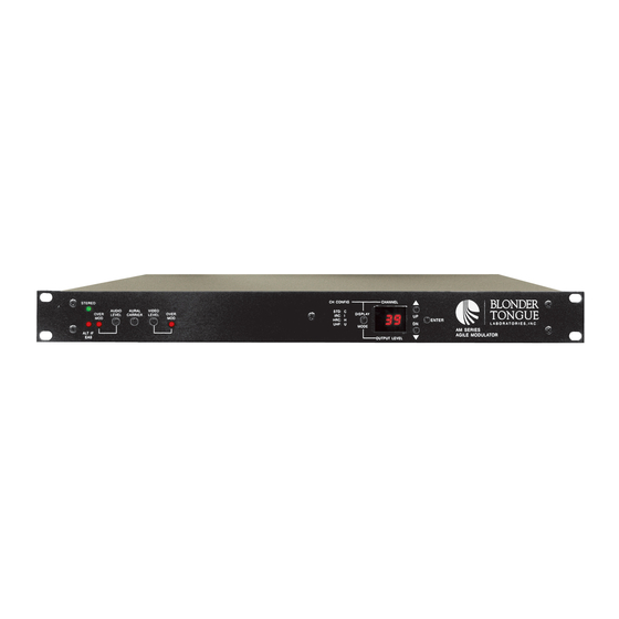
Page 26: Aqm - Agile Qam Modulator
The AQM is easily accommodated in Blonder Tongue’s standard HE Series of micro-modular rack chassis units (MIRC-12V) and the MIPS power supply units. This allows existing modulators or demodulators to coexist effortlessly. - Page 27 AQM - Agile QAM Modulator Unit Front Panel Unit Rear Panel 1. Power - 3 pin female con- 1. LCD Display - 2 line Liquid nector used to plug-in cable Crystal Display screen used for respective modulator to to interact with user to deliver power.
- Page 28 AQM - Agile QAM Modulator Main Interactive Sequence The main interactive sequence is where all the core module programming is performed. This sequence is accessed anytime a user depresses one of the t (L) or u (R) and ▲ (UP) ▼ (DN) arrow navigation keys.
- Page 29 AQM - Agile QAM Modulator Programming a Variable 1. When a user arrives at a screen whose variable needs to be changed, the user depresses the ENTER button until the blinking cursor is displayed. 2. After the blinking cursor is displayed the user simply presses the ▲...
- Page 30 AQM - Agile QAM Modulator Interleaver The Convolutional Interleaver is user selectable. Various choices are available depending on the Operation Mode.The standard settings are as follows: ITU-A - I 12, J17 ITU-B - I 128, J1 Baud Rate The Baud Rate needs to be programmed based on the Input Data and QAM Mode used.
- Page 31 AQM - Agile QAM Modulator RF OUT The unit presents a fully modulated QAM RF output. There are two modes that determine the upconversion programming. NTSC: The NTSC mode permits programming the RF output using a standard NTSC channel number. MHz: The MHz or Frequency Tuning mode permits programming the RF output to the desired frequency.
-
Page 32: Factory Reset
AQM - Agile QAM Modulator Bit Rate This is the actual input date rate that the QAM signal is locked to. This is only displayed in the QAM Out Normal Mode. Factory Reset The unit has a “Factory Reset” capability built in that allows a user to erase all the current programming information for the AQM and restore it to it’s factory default setting. -
Page 33: Aqt - Atsc To Qam Transcoder
AQT - ATSC to QAM Transcoder The Blonder Tongue ATSC to QAM Transcoder is a modular unit that allows the reception of a modulated 8VSB or QAM signal input and transcodes it to a QAM modulated output signal. The unit is designed to tune to an off-air 8VSB or QAM digital signal and convert it to a digital QAM signal to permit interface with digital TV displays with QAM tuners. - Page 34 AQT - ATSC to QAM Transcoder...
- Page 35 AQT - ATSC to QAM Transcoder...
- Page 36 AQT - ATSC to QAM Transcoder Operating Interface Instructions Boot-Up Display Sequence When the unit is first plugged in for use, the PCM displays the appro- priate module condition on the LCD readout as depicted below. AQT - Boot-Up Display Sequence 1.
- Page 37 AQT - ATSC to QAM Transcoder Loop Display Sequence After the unit has displayed the boot-up sequence it proceeds to the loop sequence. In this mode the LCD displays the actual module status as depicted by the diagram below. This information is referred as the loop sequence because this information is constantly displayed in a scrolling fashion on the LCD readout.
- Page 38 AQT - ATSC to QAM Transcoder Left/Right Sequence Details The Left/Right sequence is where the core variables of the AQT are programmed. It is accessed when a user depresses the t (L) or u (R) arrow navigation keys. There are 4 main adjustable variables for each module.
- Page 39 AQT - ATSC to QAM Transcoder • OUTPUT CATV — permits the entry of the desired output channel number to program the AQT module, tuning range is NTSC CATV channel 2—135, (digital center frequency) • INPUT FREQ — permits the entry of the desired input signal center frequency to program the AQT module, tuning in frequency range of 54—864 MHz, (digital center frequency) •...
- Page 40 AQT - ATSC to QAM Transcoder Each of the modules are displayed in order by scrolling through the sequence to find the desired variable on a respective installed module. Modules not installed are listed by the "MODULE IS NOT PRESENT" message. The SNR value for each module is displayed together for each of the installed eight modules at the end of the sequence.
- Page 41 AQT - ATSC to QAM Transcoder Interactive & Up/Down Sequence The advanced interactive menu is easily accessible by depressing the p (UP) or q (DN) arrow keys on the front of the control module. Each of the adjustable settings are issued to the particular module that is actively displayed.
- Page 42 AQT - ATSC to QAM Transcoder • INPUT BROWSE — when "activated" the input browse function automatically scans the input signal for the 8VSB/QAM rates as per the chart below. Then, if found, automatically sets the input and output parameters. If no valid signal is found it will default to the last locked state.
-
Page 43: Aqt Quick Set-Up Instruction Guide
AQT - ATSC to QAM Transcoder AQT Quick Set-Up Instruction Guide The Quick Set-Up instructions are provided as a checklist of the minimum steps required to install and program the AQT. 1. Verify all cable connections a. Check to make sure the power/data cables are connected to the correct location on the PCM and the respective modules to ensure proper communication b. -
Page 44: Dap - Digital To Analog Processor
DAP - Digital to Analog Processor The Digital to Analog Processor (DAP) is a complete single channel solution for delivering digital television programming over existing analog networks. The DAP is housed in a one rack high unit and features a backlit 2 x 16 character LCD screen and push button navigation switches to allow interaction with the simple to follow user menu functions for programming. - Page 45 DAP - Digital to Analog Processor...
- Page 46 DAP - Digital to Analog Processor...
- Page 47 DAP - Digital to Analog Processor Boot-Up Display Sequence When the unit is first plugged in for use, the DAP displays the appro- priate module condition on the LCD readout as depicted below. Boot-Up Display Sequence 1. Each DAP unit has a unique digital address that is set at the factory which is displayed immediately following the power status initialization.
- Page 48 DAP - Digital to Analog Processor Main LCD Lock Display After the unit has displayed the boot-up sequence it will display the main LCD lock display. In this mode the LCD displays the actual status as depicted in the diagram below. The LCD lock display may be interrupted at any time by pressing the any of the arrow keys.
- Page 49 DAP - Digital to Analog Processor The Unit LED has a backlit feature to illuminate the panel. It will illuminate when any of interactive buttons are pressed. It will auto- matically turn off if no button interaction is made after 10 seconds. DAP - Left/Right Display Interactive &...
- Page 50 DAP - Digital to Analog Processor Programming a Variable 1. Press the ▲ (UP) or ▼ (DN) arrow navigation keys to scroll to the desired interactive variable. 2. When a user arrives at a screen whose variable needs to be changed, the user should depress the ENTER button until the blinking cursor is displayed.
- Page 51 DAP - Digital to Analog Processor INPUT CH PLAN: The CHANNEL PLAN mode allows the user to the select the appro- priate frequency mode. This setting alerts the user to the appropriate center frequency plan the DAP will use during the scan process. •...
- Page 52 DAP - Digital to Analog Processor TUNE CHANNEL: The TUNE CHANNEL command allows a user to select the desired program from the list of available channels from the unit scan. To select a program scroll to the desired item in the channel list and press the Enter key.
- Page 53 DAP - Digital to Analog Processor PICTURE SHAPE: The DAP operator can adjust the picture shape to the desired setting for converting 16:9 images to 4:3 images as required for traditional television ratio viewing. (The Center Cut setting is recommended in most applications) •...
- Page 54 DAP - Digital to Analog Processor CC:EIA-608: This is the Closed Captioning command mode. The Closed Captioning, also known as line 21 captions per EIA-608 is the standard for Closed Captioning for NTSC Broadcasts in the United States. An operator can globally enable or disable Closed Captioning for each module eliminating the need to adjust individual TV viewing locations.
- Page 55 DAP - Digital to Analog Processor Analog Output Adjustments (Front Panel) VIDEO LEVEL: With the intended signal source connected and a representative video program present, turn the Video Level adjust control clockwise until the Video Overmodulation light just flashes, then back off slightly.
-
Page 56: Dap Quick Set-Up Instruction Guide
DAP - Digital to Analog Processor DAP Quick Set-Up Instruction Guide The Quick Set-up instructions are provided as a checklist of the minimum steps required to install and program the Digital to Analog Processor. 1. Verify RF input levels a. Signal acquisition range is -20 to +20 dBmV — -10 to +10 dBmV is the desired optimum level 2. -
Page 57: Qt - Modular Qpsk/Qam Transcoder
Interfacing the QT with Blonder Tongue’s QCentral computer software provides off-site, remote operation and control including digital adjustment of the QAM RF output level. - Page 58 QT - Modular QPSK/QAM Transcoder...
- Page 59 QT - Modular QPSK/QAM Transcoder...
-
Page 60: Qpsk/Qam Transcoders
QPSK/QAM Transcoders Boot-Up Display Sequence When the unit is first plugged in for use, the control module interrogates the potential transcoder connections and displays the appropriate module condition on the LCD readout as depicted below. Boot-Up Display Sequence Upon completion of the boot-up sequence the transcoder is ready for use and will proceed to the loop display sequence. - Page 61 QPSK/QAM Transcoders Programming a Variable Press the Left or Right arrow buttons to access the interactive variables. 1. When a user arrives at a screen that a variable needs to be changed, the user depresses and holds the ENTER button until the blinking cursor is displayed (approximately one second).
- Page 62 QPSK/QAM Transcoders QAM Modes The transcoders have three QAM modes. NORMAL: The normal QAM mode outputs a 6 MHz QAM modulated signal. OFF: The off QAM mode outputs no signal from the module. (When a module is placed in the QAM OFF Mode, the STATUS LED indicator will blink).
- Page 63 QPSK/QAM Transcoders Factory Reset The units have a “Factory Reset” capability built in that allows a user to erase all the current programming information for the PSCM/PCM and restore it to it’s factory default setting. To perform this function, press and hold the (UP) (DN) arrow navigation keys simultaneously until the LCD ▼...
- Page 64 QPSK/QAM Transcoders The following are the default factory settings the unit will reset to: QT Series # 7 OUT CH 107 # 1 OUT CH 101 # 7 INPUT 974 MHz # 1 INPUT 974 MHz QAM: NORMAL QAM: NORMAL LEVEL: 40 dBmV LEVEL: 40 dBmV # 8 OUT CH 108...
-
Page 65: Broadband Amplifier Specifications Chart
Broadband Amplifier Specifications Chart... -
Page 66: Directional Couplers Insertion Loss
TL-PI-1000 #3850 Terminated 1948-11 TLS-1000 1948-14 #3851 1948-17 1948-20 TLS-1000-2 1948-23 #3855 1948-26 1948-29 TLS-1000-3 1948-32 #3856 1948-35 TLS-1000-3U 5.0/8.5 6.0/9.2 #3857 (unbalanced) Please refer to the Blonder Tongue catalog for more detailed specifications common to indoor and outdoor passives. -
Page 67: Megaport Components
MegaPort Components MegaPort Gateway (MPG) This is the interface between the trunk data network and the coax. Each MPG supports up to 64 MPOs and is connected at the coax's point of entry to the building, community, campus or individual home. RF Connector Power Cable... - Page 68 MegaPort Methods of Installation Case Study The diagram below is an example of multiple users situated between amplifiers. 20 Users 20 Users 30 Users Band Stop Filter Double Tap (BSF) Upstream and Downstream Signal Settings Frequency Diversity Frequency Diversity is when each MPG DS and US carrier are set at a different frequency.
- Page 69 MegaPort Software Utilities - ConfigIO ConfigIO Utility Software ConfigIO is an application designed to let the technician see the link stat settings. There is a protocol that needs to be installed in the connection properties. Ethernet - TMT Management Protocol Driver USB - Ndisuio.inf protocol In order to see data of the IO/MPO components, go to the 'Summary' tab.
- Page 70 MegaPort Manager MegaPort Manager Main Screen - with MPO’s installed. Note: Visit the Blonder Tongue FTP Site for the latest software releases and updates at ftp://ftp1.blondertongue.com...
- Page 71 MegaPort Manager - RF Data In order to adjust an RF parameter, open the “Configure MPG” dialog box. You can do that by double-clicking the “MPG” node, or by pressing Ctrl+B. Click the Downstream or Upstream tab. Downsteam Center Frequency Downsteam Downsteam Modulation...
- Page 72 MegaPort Manager IO Upstream Frequency IO Upstream Bandwidth IO Upstream Symbol Rate Receiving Level IO Upstream Modulation Note: If US parameter is being changed the change will take effect for the IO automatically.
- Page 73 MegaPort Manager - Tips By clicking on the column header of the detail pane, the user can sort in ascending or descending order. To add remove columns, you can either right-click the columns header or click on the ‘View’ menu, and then choose ‘Customize Current View…’.
- Page 74 MegaPort Manager - Troubleshooting How to verify that the IO is working properly Important: All these steps are related to a MPG that has other MPO’s that are working properly Connect the PC to the MPO and the ping the RF port of the MPG @ 192.168.0.1.
-
Page 75: Addressable Products
Addressable Products Addressable off-premise interdiction can be used in a total deploy- ment where all homes are controlled by interdiction, or a limited deployment where a subset of homes are controlled. The “inter- diction” terminology comes from the fact that the interfering or jamming signal is introduced into the premium channel at the subscriber’s location, not at the headend as with conventional scrambling systems. -
Page 76: Jamming Capability
Jamming Capability Each Addressable Field Unit consists of various oscillator configurations that are used to generate the jamming signals. Each oscillator may be shared among multiple channels within a set band of frequencies. The VMI, SMI and TVCB oscillator configurations are shown below for example. -
Page 77: Vmi System Design
VMI System Design VMI Directional Coupler (DC) Table 0, 4, 8, 11, 14, 17 dB Insertion Loss 0 8 11 14 17 5 MHz: NA 4.0 3.0 2.1 1.3 1.7 1.1 dB 54 MHz: NA 3.3 2.9 1.2 0.8 .08 .06 dB 550 MHz: NA 4.3 4.2 2.3 1.4 1.3 1.0 dB 750 MHz: NA 4.8 4.5 2.7 1.7 1.7 1.1 dB 860 MHz: NA 4.7 4.5 2.9 2.0 1.8 1.4 dB... - Page 78 VMI System Design VMI Power Consumption Current Consumption (mA) 1 Jammer w/2 Jammer w/3 Jammer Volts (VAC) Module Modules Modules 45.00 50.00 55.00 60.00 65.00 70.00 75.00 80.00 85.00 90.00 VMI Installation Power Supply Pinout Pin# Voltage 28 VDC 12 VDC GND 6.2 VDC GND 60 VAC USED USED Minimum...
-
Page 79: Tvcb Systems Design
TVCB Systems Design Insertion Loss Specifications for Equalizers (EQ) VMI-CEQ8V 860 MHz Equalizers Tilt Comp Loss @ Loss @ Loss @ Loss @ Value @ 860 MHz 54 MHz 550 MHz 750 MHz 860 MHz -2.56 -1.12 -2.37 -3.19 -3.68 -1.87 -0.97 -1.96... -
Page 80: Power Consumption
TVCB Systems Design Power Consumption The TVCB can be powered a number of ways: 1. House powered via 120VAC outlet: Power consumption 11.8W @ 24VAC (550 mA) 2. Auxiliary or Line Powered: Power consumption 8.0W @ 60VAC (200 mA) 8.8W @ 90VAC (150 mA) Below are the power consumptions of the TVCB: Volts Curr. - Page 81 TVCB Systems Design Power Selection Power Supply Power Select RF Board Equalizer Forward Return Attenuator Attenuator RF In RF Out 60/90 Aux Power Jammer/Controller Board...
-
Page 82: Tvcb Installation
TVCB Installation Power Selection Feeder Power J 11 J 12 J 13 J 14 House Power J 11 J 12 J 13 J 14 Auxillary Power J 11 J 12 J 13 J 14 Position A 60/90 VAC Network Powering Position B 26 VAC House Powering... - Page 83 TVCB Installation Tightening Sequence Tightening: Use a criss-cross pattern to tighten the housing bolts. Tighten closure bolts between 5-7 ft. lbs. TVCB Troubleshooting Fault Action - Pulse Disconnect Pulse Disconnect has the following codes to identify which fault has occurred: •...
-
Page 84: Tvcb-Pc (Parental Controlled) System Design
TVCB-PC (Parental Controlled) System Design TV Channel Blocker Parental Controlled (TVCB-PC) enables cable television customers to block unwanted channels when they presently lack the equipment necessary to prevent unwanted channels from being viewed. The TVCB-PC provides channel blocking (ch. 2-86) to all televisions in the dwelling. -
Page 85: Tvcb-Pc Installation
TVCB-PC Installation 1. Determine mounting location, install screws for wall mounting bracket 2. Determine power source location and power supply option, position P1 appropriately 3. Power the unit, from RF Input, Subscriber Port, or Auxiliary Port (default from the factory) 4. - Page 86 TVCB-PC Installation...
- Page 87 FOR 9111 Power Supply Jumper Determines Voltage Automatic Gain Control Broadband AGC using carriers in 140 - 240 MHz range with dynamic range of ±3 dB. TVCB-PC Troubleshooting In case of failure, the small round LED may flash 4 times.
-
Page 88: Smi System Design
SMI System Design 750 MHz Directional Coupler (DC) Insertion Loss DC Feeder (through) Insertion Loss Tap Loss Reverse Path Forward Path DC Value Stock # 5 MHz 40 MHz 51 MHz 550 MHz 750 MHz 291659 Terminating Terminating 291611 Terminating Terminating 378224 Terminating... -
Page 89: Smi System Design
SMI System Design (DC) Coupled Port Loss DC Coupled Port Loss* Tap Loss Reverse Path Forward Path DC Value Stock # 5 MHz 40 MHz 51 MHz 550 MHz 750 MHz 291659 291611 378224 378225 562958 562959 562960 562961 10.6 562962 10.5 10.2... - Page 90 SMI System Design 750 MHz Equalizer Insertion Loss EQ Value Stock # 51 MHz 550 MHz 750 MHz -9.0 562996 10.4 -7.5 562995 -6.0 562994 -4.5 562993 -3.0 562992 -1.5 562991 566057 562978 562979 562980 562981 562982 562983 10.5 562984 12.0 562985 10.0...
- Page 91 SMI System Design 4-Port Power Consumption * Housing Only w/2 Module w/4 Modules Volts Current Watts Current Watts Current Watts 35.00 0.09 2.35 0.26 7.74 0.50 14.74 40.00 0.08 2.45 0.23 7.85 0.43 14.25 45.00 0.08 2.56 0.20 7.95 0.37 13.76 50.00 0.07...
- Page 92 SMI System Design 8-Port Power Consumption * Housing Only w/2 Module w/4 Modules Volts Current Watts Current Watts Current Watts 35.00 0.18 5.25 0.36 10.33 0.57 16.74 40.00 0.17 5.20 0.32 10.36 0.50 16.24 45.00 0.15 5.15 0.28 10.40 0.43 15.75 50.00 0.14...
-
Page 93: Smi Installation
SMI Installation Torque Patterns 4-PORT Start Here 8-PORT Start Here... -
Page 94: Smi Installation
SMI Installation Strand Mount (4-port) Configurations Signal Forward Direction Signal Thru Pedestal Mount (4-port) Configurations Thru Foward Foward Signal Signal... - Page 95 SMI Installation Balancing and Alignment The SMI unit has a series of jumpers whose position is determined by the RF and AC status of the unit. The selection of DC determines the RF status: values 0, 1, 2, or 3 dB are terminating and the remaining DCs (4-31.5 dB) are non-terminating DC's.
- Page 96 SMI Installation Passing Power to the Home Some 750 MHz SMI units and subscriber modules are capable of passing 37-90 VAC power to each subscriber port. This capability provides power to a telephony or data network interface unit (NIU)/customer interface unit (CIU). •...
-
Page 97: Amt System Design
AMT System Design LGTC Directional Couplers, Insertion Loss Frequency LTC0 LTC4 LTC7 LTC10 LTC13 LTC16 LTC19 LTC22 LTC25 3.75 1.67 1.19 0.80 0.93 0.60 0.60 0.60 3.65 1.68 1.25 0.85 1.02 0.65 0.65 0.65 3.45 1.48 1.02 0.66 0.75 0.50 0.50 0.50 3.45... - Page 98 AMT System Design LGT 8-Port Tap Losses Frequency LTC0 LTC4 LTC7 LTC10 LTC13 LTC16 LTC19 LTC22 LTC25 10.1 35.5 13.2 17.4 19.9 22.8 26.2 29.4 32.5 35.4 10.1 13.2 17.4 22.8 26.2 19.9 29.4 32.5 35.3 10.0 13.2 17.3 22.7 26.0 19.7 29.3...
- Page 99 AMT System Design AMT Tap Losses Frequency LTC0 LTC4 LTC7 LTC10 LTC13 LTC16 LTC19 LTC22 LTC25 24.0 11.3 14.4 21.1 27.4 30.6 33.7 36.7 18.6 23.6 10.9 14.0 20.7 27.0 30.2 33.3 36.2 18.2 23.9 11.2 14.4 20.9 27.2 30.5 33.6 36.5 18.5...
-
Page 100: Amt Installation
AMT Installation Mounting Configurations... -
Page 101: Amt Installation
AMT Installation Mounting Configurations Switch Blade Connector Terminal Pedestal Aerial Configuration Configuration Pedestal Center Aerial Post Post Post Platform... -
Page 102: Basic Cable Theory Useful Technical Data
Basic Cable Theory Useful Technical Data The Decibel The decibel (dB) provides a means of representing large power ratios as manageable, small numbers, and allows the overall gains and losses in a module or a network to be calculated by addition and subtraction, rather than by multiplication and division. -
Page 103: Power Conversions
Power Conversions dBmV A power measurement of ‘x dBmV’ indicates that a particular signal is x dB greater than (‘above’) 1 millivolt in 75 ohms. A negative dBmV value indicates that the signal is x dB less than (‘below’) 1 millivolt in 75 ohms. To convert x millivolts to dBmV: dBµV Similarly, a measurement of ‘x dBµV’... -
Page 104: Power Conversion
Power Conversion A power level, in dBmV, can be converted directly to power in dBm, if the impedance, Z. is known: To convert x dBmV directly to dBm: The inverse operation is also possible if impedance is known: To convert dBm directly to dBmV: Impedance Mismatch It frequently happens that the input impedance of a measuring device (spectrum analyzer;... -
Page 105: Standard Resistor Color Codes And Values
Standard Resistor Color Codes and Values FIRST SECOND MULTIPLICATION BLACK =0 BLACK =0 SILVER MULTIPLY BY 0.01 BROWN =1 BROWN =1 GOLD MULTIPLY BY 0.1 RED =2 RED =2 BLACK MULTIPLY BY 1 ORANGE =3 ORANGE =3 BROWN MULTIPLE BY 10 YELLOW =4 YELLOW =4 MULTIPLY BY 100... - Page 106 Standard Resistor Color Codes and Values ±1% Standard Resistor Values (Ohm) Values from 10 Ohm to 22 Mega Ohm by powers of 10. 10.0 13.3 17.8 23.7 31.6 42.2 56.2 75.0 10.2 13.7 18.2 24.3 32.4 43.2 57.6 76.8 10.5 14.0 18.7 24.9...
-
Page 107: System Calculations
System Calculations Carrier/Cross Modulation (XM) 1. Cross Modulation for One Amplifier at Operating Level: 2. To Sum Identical Cross Modulation Ratios: See charts & examples starting on pages 84. 3. To Sum Different Cross Modulation Ratios: See examples starting on pages 84. 4. - Page 108 System Calculations Carrier/Composite Triple Beat (CTB) 1. Composite Triple Beat for One Amplifier at Operating Level: 2. To Sum Identical Composite Triple Beat Ratios: See charts & examples starting on pages 84. 3. To Sum Different Composite Triple Beat Ratios: See examples starting on pages 84.
- Page 109 System Calculations Carrier/Single Second Order Distortion (C/SSO) 1. Single Second Order Beat for One Amplifier at Operating Level: 2. To Sum Identical SSO Ratios: See charts & examples starting on pages 84. 3. To Sum Different SSO Ratios: A 1 dB change of the output of an amplifier will change SSO by 1 dB.
- Page 110 System Calculations Carrier/Composite Second Order Distortion (C/CSO) 1. Composite Second Order for One Amplifier at Operating Level: 2. To Sum Identical CSO Ratios: See charts & examples starting on pages 84. 3. To Sum Different CSO Ratios: See examples starting on pages 84. 4.
- Page 111 System Calculations Composite Intermodulation Noise (CIN) It is assumed that CIN is dominated by 3rd order distortion (CIN3). This is the case in systems with analog television channels to 550 MHz and digital video above 550 MHz. 1. Composite Intermodulation Noise for One Amplifier at Operating Level.
- Page 112 System Calculations Carrier/Hum Modulation (C/H) 1. To Sum Identical Carrier/Hum Ratios: See charts & examples starting on pages 84. 2. To Sum Different Carrier/Hum Ratios: See examples starting on page 84. Note: Above calculations assume connection of all power supplies to the same powerline phase.
- Page 113 System Calculations Carrier/Noise 1. The Carrier/Noise contribution of a single amplifier when the Noise Figure (NF) is known: 2. To Sum Identical Carrier/Noise Ratios: See charts & examples starting on pages 84. 3. To Sum Different Carrier/Noise Ratios: See examples starting on pages 84. 4.
- Page 114 System Calculations TVRO Formulas 1. System Gain Over Temperature Ag = Antenna Gain (dB) AT = Antenna Temperature (˚K) LNAT = Low Noise Amp Temperature (˚K) 2. Carrier to Noise Ratio* 3. C/N for other RxBw 4. Convert C/N to S/N* 5.
- Page 115 System Calculations Aximuth and Elevation Angles Antenna pointing angles can be calculated in degrees from true north from the following equations: Where ∆ is the absolute value of the difference between satellite and TVRO site longitudes and Φ is the site latitude. Noise Temperature &...
- Page 116 For example, what is the maximum acceptable peak-to- valley deviation at the 32nd amplifier in a cascade? Thus, 4.2 dB is the maximum acceptable peak-to-valley deviation (highest peak to lowest valley in the broadband signal) at the 32nd amplifier.
- Page 117 System Calculations Amplifier Cascade Factor C/N + SSO CTB & XMOD CASCADE (N) 10*LOG(N) 15*LOG(N) 20*LOG(N) 0.00 0.00 0.00 3.01 4.52 6.02 4.77 7.16 9.54 6.02 9 03 12.04 6.99 10.48 13.98 7.78 11.67 15.56 8.45 12.68 16.90 9.03 13.55 18.06 9.54 14.31...
- Page 118 System Calculations Amplifier Cascade Factor - Example The Amplifier Cascade Factor Chart (on previous page) is used to predict performance considering the contribution of various numbers of amplifiers. It assumes that all amplifiers are operated at the same level (input level for noise, output level for distortion).
- Page 119 System Calculations Note: Summing different ratios requires a grasp of the antilog concept. For brevity, the example shown is for CTB only, but the approach is identical for all system distortion and noise calculations. Determine End Of Line CTB Given The Following: 10 Trunk CTB = 65 dBc 1 Bridger CTB = 60 dBc 3 Line Extender CTB = 58 dBc...
-
Page 120: 20 Log Function Derate Chart
20 Log Function Derate Chart (use for CTB and XMOD) diff SUBTRACTION VALUES (dB) 0.00 0.10 0.20 0.30 0.40 0.50 0.60 0.70 0.80 0.90 6.02 5.97 5.92 5.87 5.82 5.77 5.73 5.68 5.63 5.58 5.53 5.49 5.44 5.39 5.35 5.30 5.26 5.21 5.17 5.12... -
Page 121: Log Function Derate Chart
10 Log Function Derate Chart (use for CNR and SSO) diff SUBTRACTION VALUES (dB) 0.00 0.10 0.20 0.30 0.40 0.50 0.60 0.70 0.80 0.90 3.01 2.96 2.91 2.86 2.81 2.77 2.72 2.67 2.63 2.58 2.54 2.50 2.45 2.41 2.37 2.32 2.28 2.24 2.20 2.16 2.12 2.09... -
Page 122: Combining Two X-Mod Or Ctb Performance Ratings (20 Log)
Combining Two X-MOD or CTB Performance Ratings (20 Log) 10 Trunk CTB = 65 dBc Using dB Subtraction Values 1 Bridger CTB = 60 dBc The 20 log & 10 log derate Line Extender CTB = 58 dBc charts are used to sum different ratios. -
Page 123: Beat Packet Quantity
Beat Packet Quantity 330 MHz 450 MHz 550 MHz 600 MHz 750 MHz 40 Channels 60 Channels 77 Channels 85 Channels 110 Channels Frequency CTB CSO CTB CSO CTB CSO 55.25 1104 1384 2465 61.25 1137 1421 2515 67.25 1167 1455 2561 77.25... - Page 124 Beat Packet Quantity 330 MHz 450 MHz 550 MHz 600 MHz 750 MHz 40 Channels 60 Channels 77 Channels 85 Channels 110 Channels Frequency CTB CSO CTB CSO CTB CSO CTB CSO CTB CSO 421.25 1891 2415 4259 427.25 1875 2403 4259 433.25...
-
Page 125: Fiber Optics
Fiber Optics Fiber Loss vs Path Length - Single Mode @1550 nm... -
Page 126: Fiber Optics
Fiber Optics Siecor MIC™ Cable Fiber Identification Guide (SOLID) (DASHED) (STRIPED) 1 -1O 11 -20 21-30 1 Blue 11 Blue + Black Dash 21 Blue + Black Stripe 2 Orange 12 Orange+ Black Dash 22 Orange+ Black Stripe 3 Green 13 Green+ Black Dash 23 Green+ Black Stripe 4 Brown 14 Brown+ Black Dash 24 Brown+ Black Stripe 5 Slate 15 Slate+ Black Dash 25 Slate+ Black Stripe 6 White 16 White+ Black Dash 26 White+ Black Stripe 7 Red 17 Red+ Black Dash 27 Red+ Black Stripe 8 Black... - Page 127 Fiber Optics Converting MW to DBM Use the conversion table below, to convert milliwatts (mW) to decibel milliwatts (dBm). 0.1 -10.0 2.0 3.01 0.2 -6.99 3.0 4.77 0.3 -5.23 4.0 6.02 0.4 -3.97 5.0 6.99 0.5 -3.00 6.0 7.78 0.6 -2.20 7.0 8.45 0.7 -1.55...
- Page 128 Fiber Optics Transmitter Design Tool FIBT/MIBT-S3A-8XX & FIBT-10-1550 The optimal RF input level needed at the transmitter is based on channel loading. Find the channel loading figure on the X axis on the chart below. Follow this intersection across to the Y axis to determine the RF input level. This is the level that you need to apply to the transmitter to ensure a quality signal for your channel loading configuration.
- Page 129 Fiber Optics FRDA/FRRA Series RF Attenuation Requirements The RF output level from the optical receiver module varies consider- ably over its operational optical input range. It is also dependent upon the transmitter’s channel loading, its resultant RF input level and the FRRA/FRDA RF output capability. In order not to overload the ampli- fier section input, an internal attenuator must be installed. To find the recommended attenuator value, first determine the receivers opti- cal input level as noted in the "Input Optical Power”. Refer to the Configuration Table below, locate the power monitor voltage or input dBm in the left hand columns. Read across on the corre- sponding row to find the value required. FRRA-S4A-860P Model CH. Loading 110 CH. Output Level 34/42 Optical Input...
- Page 130 Fiber Optics FIBT Design Tool Laser Power Monitor This jack allows accurate measurements of the optical output power with a standard voltmeter. The voltage is scaled at 0.1VDC per mW of optical output. T herefore, mW = VDC x 10. Output level in dBm = 10 x LOG(mW). E xample: A 1.0 VDC reading is therefore a 10 mW or 10 dBm of optical output power. Refer to the table below. Laser Power 0.1 V/mW Monitor 0.25 2.51 0.32 3.16 0.40 3.98 0.50 5.01 0.63 6.31 0.79 7.94 1.00 10.00 1.26...
- Page 131 Fiber Optics Optical Coupler Design Tool Coupler Ports Ratio Loss (dB) 1 x 2 50/50 3.6/3.6 40/60 4.7/2.7 30/70 6.0/1.9 20/80 7.9/1.2 10/90 11.3/0.6 5/95 15.1/0.5 Coupler Ports Ratio Loss (dB) 1 x 3 33/33/33 6.0/6.0/6.0 40/30/30 4.7/6.4/6.4 50/25/25 3.6/7.3/7.3 60/20/20 2.7/8.4/8.4 70/15/15 1.9/9.6/9.6 80/10/10 1.2/11.3/11.3 Coupler Ports Ratio Loss (dB) 1 x 4 25% per port...
-
Page 132: Frequency Charts
Frequency Charts CATV Channels, North America EIA Standard Incremental Harmonic CH. CH. Video Audio Video Audio Video Audio T7 none 7.0000 11.5000 T8 none 13.0000 17.5000 T9 none 19.0000 23.5000 T10 none 25.0000 29.5000 T11 none 31.0000 35.5000 T12 none 37.0000 41.5000 T13 none 43.0000 47.5000 T14 none... -
Page 133: Catv Channels, North America
Frequency Charts CATV Channels, North America EIA Standard Incremental Harmonic CH. CH. Video Audio Video Audio Video Audio M 26* 235.2625 239.7625 235.2625 239.7625 234.0117 238.5117 N 27* 241.2625 245.7625 241.2625 245.7625 240.0120 244.5120 O 28* 247.2625 251.7625 247.2625 251.7625 246.0123 250.5123 P 29* 253.2625 257.7625 253.2625 257.7625 252.0126 256.5126 Q 30* 259.2625 263.7625 259.2625 263.7625 258.0129 262.5129 R... - Page 134 Frequency Charts CATV Channels, North America EIA Standard Incremental Harmonic CH. CH. Video Audio Video Audio Video Audio BBB 64 463.2500 467.7500 463.2625 467.7625 462.0231 466.5231 CCC 65 469.2500 473.7500 469.2625 473.7625 468.0234 472.5234 DDD 66 475.2500 479.7500 475.2625 479.7625 474.0237 478.5237 EEE 67 481.2500 485.7500 481.2625 485.7625 480.0240 484.5240 FFF 68 487.2500 491.7500 487.2625 491.7625 486.0243 490.5243 GGG...
- Page 135 Frequency Charts CATV Channels, North America EIA Standard Incremental Harmonic CH. CH. Video Audio Video Audio Video Audio 107 691.2500 695.7500 691.2625 695.7625 690.0345 694.5345 108 697.2500 701.7500 697.2625 701.7625 696.0348 700.5348 109 703.2500 707.7500 703.2625 707.7625 702.0351 706.5351 110 709.2500 713.7500 709.2625 713.7625 708.0354 712.5354 111 715.2500 719.7500 715.2625 719.7625 714.0357 718.5357 112 721.2500 725.7500 721.2625 725.7625 720.0360 724.5360 113 727.2500 731.7500 727.2625 731.7625 726.0363 730.5363...
- Page 136 Frequency Charts CATV Channels, North America EIA Standard Incremental Harmonic CH. CH. Video Audio Video Audio Video Audio 144 913.2500 917.7500 913.2625 917.7625 912.0456 916.5456 145 919.2500 923.7500 919.2625 923.7625 918.0459 922.5459 146 925.2500 929.7500 925.2625 929.7625 924.0462 928.5462 147 931.2500 935.7500 931.2625 935.7625 930.0465 934.5465 148 937.2500 941.7500 937.2625 941.7625 936.0468 940.5468 149 943.2500 947.7500 943.2625 947.7625 942.0471 946.5470 150 949.2500 953.7500 949.2625 953.7625 948.0474 952.5474...
-
Page 137: Catv Qam Channel Center Frequency 54 Mhz To 860 Mhz
Frequency Charts CATV QAM Channel Center Frequency - 54 MHz to 860 MHz MHz MHz MHz EIA Center EIA Center EIA Center Frequency Frequency Frequency 100 101 102 103 104 105 106 107 108 109 110 111 112 113 114 115 116 117 118 119 120 121 122 123 124 125 126 127 128... - Page 138 Frequency Charts Off Air Channels, North America (CCIR Standard M; NTSC) CH. BW (MHz) VIDEO CHROMA AUDIO Lo VHF 54-60 55.25 58.83 59.75 60-66 61.25 64.83 65.75 66-72 67.25 70.83 71.75 76-82 77.25 80.83 81.75 82-88 83.25 86.83 87.75 Hi VHF 174-180 175.25 178.83 179.75 180-186 181.25 184.83 185.75 186-192 187.25 190.83 191.75 192-198 193.25...
-
Page 139: Off Air Channels, North America (Ccir Standard M; Ntsc)
Frequency Charts Off Air Channels, North America (CCIR Standard M; NTSC) CH. BW (MHz) VIDEO CHROMA AUDIO UHF 620-626 621.25 624.83 625.75 626-632 627.25 630.83 631.75 632-638 633.25 636.83 637.75 638-644 639.25 642.83 643.75 644-650 645.25 648.83 649.75 650-656 651.25 654.83 655.75 656-662 657.25 660.83 661.75 662-668 663.25 666.83 667.75 668-674 669.25 672.83... -
Page 140: Pal B Channels
PAL B Channels Channel Channel Visual Carrier Aural Carrier Designation Designation Frequency Frequency Band Standard Ordering MHz 38.90 33.40 48.25 53.75 55.25 60.75 62.25 67.75 S01 105.25 110.75 S02 112.25 117.75 S03 119.25 124.75 S04 126.25 131.75 S05 133.25 138.75 S06 140.25 145.75 S07 147.25 152.75 S08 154.25... - Page 141 PAL B Channels Channel Channel Visual Carrier Aural Carrier Designation Designation Frequency Frequency Band Standard Ordering MHz S25 S25 335.25 340.75 S26 S26 343.25 348.75 S27 S27 351.25 356.75 S28 S28 359.25 364.75 S29 S29 367.25 372.75 S30 S30 375.25 380.75 S31 S31 383.25 388.75 S32 S32 391.25...
-
Page 142: Pal G Channels
PAL G Channels Channel Channel Visual Carrier Aural Carrier Designation Designation Frequency Frequency Band Standard Ordering MHz IV U21 471.25 476.75 IV U22 479.25 484.75 IV U23 487.25 492.75 IV U24 495.25 500.75 IV U25 503.25 508.75 IV U26 511.25 516.75 IV U27 519.25 524.75 IV U28 527.25... - Page 143 PAL G Channels Channel Channel Visual Carrier Aural Carrier Designation Designation Frequency Frequency Band Standard Ordering MHz U50 703.25 708.75 U51 711.25 716.75 U52 719.25 724.75 U53 727.25 732.75 U54 735.25 740.75 U55 743.25 748.75 U56 751.25 756.75 U57 759.25 764.75 U58 767.25 772.75 U59 775.25 780.75 U60...
-
Page 144: Pal D Channels
PAL D Channels Channel Channel Visual Carrier Aural Carrier Designation Designation Frequency Frequency Standard Ordering MHz 38.00 31.50 DS-1 49.75 56.25 DS-2 57.75 64.25 DS-3 65.75 72.25 DS-4 77.25 83.75 DS-5 85.25 91.75 Z-1 Z01 112.25 118.75 Z-2 Z02 120.25 126.75 Z-3 Z03 128.25 134.75 Z-4 Z04... - Page 145 PAL D Channels Channel Channel Visual Carrier Aural Carrier Designation Designation Frequency Frequency Standard Ordering MHz Z-16 Z16 288.25 294.75 Z-17 Z17 296.25 302.75 Z-18 Z18 304.25 310.75 Z-19 Z19 312.25 318.75 Z-20 Z20 320.25 326.75 Z-21 Z21 328.25 334.75 Z-22 Z22 336.25 342.75 Z-23 Z23 344.25...
-
Page 146: Pal K Channels
PAL K Channels Channel Channel Visual Carrier Aural Carrier Designation Designation Frequency Frequency Standard Ordering MHz 38.00 31.50 DS-13 U13 471.25 477.75 DS-14 U14 479.25 485.75 DS-15 U15 487.25 493.75 DS-16 U16 495.25 501.75 DS-17 U17 503.25 509.75 DS-18 U18 511.25 517.75 DS-19 U19 519.25 525.75 DS-20... - Page 147 PAL K Channels Channel Channel Visual Carrier Aural Carrier Designation Designation Frequency Frequency Standard Ordering MHz DS-39 U39 719.25 725.75 DS-40 U40 727.25 733.75 DS-41 U41 735.25 741.75 DS-42 U42 743.25 749.75 DS-43 U43 751.25 757.75 DS-44 U44 759.25 765.75 DS-45 U45 767.25 773.75 DS-46 U46 775.25...
-
Page 148: Pal I Channels
PAL I Channels Aural Carrier Channel Channel Visual Carrier Frequency Frequency Designation Designation Ordering (MHz) (MHz) Standard 32.90 38.90 56.00 62.00 64.00 70.00 78.00 72.00 80.00 86.00 94.00 88.00 96.00 102.00 104.00 110.00 112.00 118.00 120.00 126.00 134.00 128.00 136.00 142.00 150.00 144.00 152.00 158.00 160.00 166.00... - Page 149 PAL I Channels Channel Channel Visual Carrier Aural Carrier Frequency Frequency Designation Designation Ordering (MHz) (MHz) Standard 336.00 342.00 344.00 350.00 352.00 358.00 366.00 360.00 368.00 374.00 382.00 376.00 384.00 390.00 392.00 398.00 400.00 406.00 408.00 414.00 422.00 416.00 424.00 430.00 432.00 438.00 440.00 446.00 448.00 454.00...
- Page 150 PAL I Channels Channel Channel Visual Carrier Aural Carrier Frequency Frequency Designation Designation Ordering (MHz) (MHz) Standard 31.50 38.00 471.25 477.25 479.25 485.25 493.25 487.25 495.25 501.25 509.25 503.25 511.25 517.25 519.25 525.25 527.25 533.25 535.25 541.25 549.25 543.25 551.25 557.25 565.25 559.25 567.25 573.25 575.25 581.25...
- Page 151 PAL I Channels Channel Channel Visual Carrier Aural Carrier Frequency Designation Designation Frequency Ordering (MHz) (MHz) Standard 727.25 733.25 741.25 735.25 743.25 749.25 751.25 757.25 759.25 765.25 767.25 773.25 775.25 781.25 783.25 789.25 797.25 791.25 799.25 805.25 807.25 813.25 815.25 821.25 823.25 829.25 837.25 831.25 839.25 845.25...
-
Page 152: Fm Broadcast Channel Frequencies (Mhz)
FM Broadcast Channel Frequencies (MHz) Channel Frequency Channel Frequency Channel Frequency 88.1 94.9 101.7 88.3 95.1 101.9 88.5 95.3 102.1 88.7 95.5 102.3 88.9 95.7 102.5 89.1 95.9 102.7 89.3 96.1 102.9 89.5 96.3 103.1 89.7 96.5 103.3 89.9 96.7 103.5 90.1 96.9 103.7 90.3 97.1 1039... -
Page 153: International Channel Standards
International Channel Standards Broadcast Color Standard Channel Country System VHF UHF Frequencies Argentina PAL Amer Australia PAL Australian Austria PAL West Euro Bahamas NTSC Amer Belgium PAL West Euro Bermuda NTSC Amer Bolivia NTSC Amer Brazil PAL Amer Canada NTSC Amer Chile NTSC Amer China PAL Chinese China, Rep... - Page 154 International Channel Standards Broadcast Color Standard Channel Country System VHF UHF Frequencies Israel PAL West Euro Italy PAL Italian Japan Jordan PAL West Euro Korea S. NTSC Amer Malaysia PAL West Euro Mexico NTSC Amer Morocco SECAM Morocco Netherlands PAL West Euro New Zealand PAL Norway PAL West Euro Panama NTSC Amer Peru...
-
Page 155: Ccir Television Transmission Characteristics
CCIR Television Transmission Characteristics For Off Air Channels LINES FIELD LINE CHAN. VIDEO VID/SND Freq. Freq. Width B/W Spacing Sideb VEST VISUAL SYSTEM (Hz) (MHz) (MHz) (MHz) (MHz) (MHz) MOD MOD AURAL B/G 625 50 15,625 7/8 + 5.5 0.75 NEG FM C 625 50 15,625 + 5.5 0.75 POS AM D/K 625... -
Page 156: Cable Tv Channel Format
Cable TV Channel Format NTSC NTSC Composite Video Waveform... -
Page 157: Us Frequency Spectrum
US Frequency Spectrum... -
Page 158: Fcc Aeronautical Band Frequencies
FCC Aeronautical Band Frequencies Used for Communication and Navigation... -
Page 159: North American Satellite C & Ku-Band
North American Satellite C & Ku-Band 101.1° W DirecTV 9S 61.5° W EchoStar 3 61.5° W 102.8° W Spaceway 1 Rainbow 1 102.8° W DirecTV 10 63.0° W Estrela do Sul 1 103.0° W AMC 1 65.0° W Star One C1 105.0° W AMC 15 70.0° W Star One C2 105.0° W AMC 18 72.0° W Nahuel 1 (incl. 0.9°) 72.0° W 107.3° W Anik F1 AMC 6 107.3° W Anik F1R 72.5° W DirecTV 1R 110.0° W DirecTV 5 74.0° W Horizons 2 EchoStar 8 110.0° W 75.0° W Brasilsat B1... -
Page 160: Programming Services
Programming Services DISH Network™ Video/Audio Programming Service EchoStar I = 148° W, 15 DBS Transponders EchoStar II = 148° W, 10 DBS Transponders EchoStar III = 61.5° W, 14 DBS Transponders EchoStar IV = 77° W, Not in Services EchoStar V = 129° W, 20 DBS Transponders EchoStar VII = 119° W, 21 DBS Transponders EchoStar VIII = 110° W, 19 DBS Transponders EchoStar IX = 121° W, 15 Ku & 2 Ka Transponders EchoStar X = 110° W, 10 DBS Transponders Rainbow 1 = 61.5° W, 7 DBS Transponders Dish Network Programming changes frequently. Please visit http://www.lyngsat.com for the latest information. - Page 161 Programming Services DirecTV® Video/Audio Programming Services DirecTV 1R = 72.5° W, 15 Transponders DirecTV 4S = 101.0° W, 32 Transponders DirecTV 5 = 109.8° W, 3 Transponders DirecTV 7S = 119.0° W, 8 Transponders DirectTV 10 = 102.8° W, 17 Ka Transponders Spaceway-1 = 102.8° W, 6 Ka Transponders Spaceway-2 = 99.2° W, 48 Ka Transponders DirecTV 9S = 101.1° W DirecTV 11 = 100.7° W DirecTV Programming changes frequently. Please visit http://www.lyngsat.com for the latest information. Bell ExpressVu™ Video/Audio Programming Services Nimiq 1 = 91° W, 32 Transponders Nimiq 2 = 82° W, 32 Transponders Bell ExpressVu Programming changes frequently. Please visit http://www.lyngsat.com for the latest information.
-
Page 162: Conversion Factors
Conversion Factors Ohm’s Law & Joule’s Law Ohm’s Law Joule’s Law V = IR P = IV V = voltage in volts P = power in watts I = current in amperes I = current in amperes R = resistance in ohms V = voltage in volts Equations Summary of Ohm’s & Joule’s Laws Ohms Law (1863) A Law in Electricity: the strength of a direct current is directly proportional to the potential difference and inversely proportional to the resistance of the circuit (Georg Simon Ohm - 1870) -
Page 163: Table Of Conversions
Table of Conversions The following table lists the conversions between voltage and power measurements for the range of signal levels commonly encountered in Broadband networks. The equations described on pages 87, 88 and 89 were used in the compilation of this table. dBmV dBµV dBmV dBµV 0.0010 -60 -108.75 0.0447 -27 -75.75 0.0011 -59 -107.75 0.0501 -26 -74.75 0.0013 -58 -106.75... - Page 164 Table of Conversions dBmV dbµV dBmV dbµV 1.9953 -42.75 158.4893 104 -4.75 2.2387 -41.75 177.8279 105 -3.75 2.5119 -40.75 199.5262 106 -2.75 2.8184 -39.75 223.8721 107 -1.75 3.1623 -38.75 251.1886 108 -0.75 3.5481 -37.75 273.8420 48.75 108.75 3.9811 -36.75 281.8383 109 0.25 4.4668...
-
Page 165: Return Loss, Reflection Coefficient, And Voltage Standing Wave Ratio (Vswr)
Return Loss, Reflection Coefficient, and Voltage Standing Wave Ratio (VSWR) Return Loss Reflec. VSWR Return Reflec. VSWR Loss (dB) Reflec. Coefficient (%) Loss (dB) Coefficient (%) 0.0 4.3 100.00 20.0 10.00 1.222 0.5 2.2 94.41 34.753 20.5 9.44 1.208 1.0 1.26 89.13 17.391... -
Page 166: Return Loss Ratio (Rlr)
Return Loss Ratio (RLR) RLR (dB) VSWR The column marked Loss Reflec., on page 137 indicates the insertion loss that is attributable to the amount of signal reflected at the device input. Note: In a 75-Ohm transmission line. -
Page 167: Conversion Factors
Conversion Factors Signal Levels 0 dBm + 48.75 dBmV /75 ohms 0 dBW + 78.75 dBmV /75 ohms 0 dBmV 60 dBµV Prefixes milli (m) 1/1,000 micro (µ) 1/1,000,000 nano (n) 1/1,000,000,000 pica (p) 1/1,000,000,000,000 kilo (k) 1,000 mega (M) 1,000,000 giga (G) 1,000,000,000 Energy/Heat 12,000 BTU One Ton 1 Watt / hour = 3.415 Btu 1 horsepower = 746 Watts 1 atmosphere = 14.6 pounds per square inch °Fahrenheit (9/5 x °C) + 32 °CELSIUS 5/9 x (°F - 32) - Page 168 Conversion Factors Volume 1 cubic yard = 27 cubic feet 1 cubic inch 16.38716 cubic centimeters 1 cubic meter = 1.307943 cubic yards 1 US gallon 3.7853 liters 1 US gallon 128 fluid ounces 1 US gallon 0.8327 Imperial Gallons 1 liter 61.025 cubic inches 1 liter 1000 cubic centimeters Weight 1 pound 16 ounces 1 pound 453.592 grams 1 kilogram 2.20462 pounds 1 kilogram 1000 grams 1 ton 2000 pounds 1 ton 907.185 kilograms 1 metric ton = 2205 pounds...
- Page 169 Conversion Factors Linear 1 mile 5280 feet 1 mile 1.60935 kilometers 1 kilometer 3280.83 feet 1 kilometer 0.621 miles 1 kilometer 1000 meters 1 meter 39.37 inches 1 meter 3.281 feet 1 meter 100 centimeters 1 centimeter = 10 millimeters 1 centimeter = 0.394 inches 1 millimeter 1000 microns 1 micron 1000 nanometers 1 foot 30.48 centimeters 1 inch 25.4 millimeters 1 inch 1000 mils 1 mil 25.4 microns 1 micron 0.3937 mil 1 yard 36 inches...
- Page 170 Conversion Factors Degrees, Fahrenheit to Celsius -40 -40.0 -40.6 -41.1 -41.7 -42.2 -42.8 -43.3 -43.9 -44.4 -45.0 -30 -34.4 -35.0 -35.6 -36.1 -36.7 -37.2 -37.8 -38.3 -38.9 -39.4 - 20 -28.9 -29.4 -30.0 -30.6 -31.1 -31.7 -32.2 -32.8 -33.3 -33.9 - 10 -23.3 -23.9 -24.4 -25.0 -25.6 -26.1 -26.7 -27.2 -27.8 -28.3 0 -17.8 -18.3 -18.9 -19.4 -20.0 -20.6 -21.1 -21.7 -22.2 -22.8 0 -17.8 -17-.2 -16.7 -16.1 -15.6 -15.0 -14.4 -13.9 -13.3 -12.8 10 -12.2 -11.7 -11.1 -10.6 -10.0 -9.4 -8.9...
-
Page 171: Temperature Conversion Nomograph
Temperature Conversion Nomograph °C °F FAHRENHEIT, °F °F = (°C x ) + 32 CELSIUS, °C °C = (°F - 32) KELVIN, °K °K = °C + 273... -
Page 172: Wire Gauge Data (Awg)
Wire Gauge Data (AWG) Diameter Area, circular Ohms per 1000 ft. Weight per mils, d 2 mils, d at 20°C, or 68° F 1000 ft. (lbs.) 0000 460.00 211,600 0.04901 640.5 000 409.64 167,805 0.06180 508.0 00 364.80 133.079 0.07793 402.8 324.86 105.534... -
Page 173: Current Ratings For Electronic Cables
Current Ratings for Electronic Cables The maximum continuous current rating for an electronic cable is limited by conductor size, number of conductors contained within the cable, maximum temperature rating of the cable, and environmental conditions such as ambient temperature and air flow. To use the current capacity chart, first determine conductor size, temperature rating, and number of conductors from the applicable product description for the cable of interest. Next, find the current value on the chart for the proper temperature rating and conductor size. To calculate the maximum current rating/conductor, multiply the chart value by the appropriate conductor factor. The chart assumes cable is surrounded by still air at an ambient temperature of 25˚ C. Current values are in RMS Amperes and are valid for copper conductors only. -
Page 174: Cable Substitution Chart (Per Nec*)
Cable Substitution Chart (Per NEC*) Type MP = Multipurpose Cables Type CM = Communications Cables Type CL2, CL3 = Class 2 and Class 3 Remote Control, Signaling and Power Limited Cables Type FPL = Power-Limited Fire Alarm Cables Type CATV = Community Antenna Television and Radio Distribution Cables Type OFN = Non-conductive Optical Fiber Cables Type OFC = Conductive Optical Fiber Cables Type PLTC =... -
Page 175: Common Catv Symbols
Common CATV Symbols... - Page 176 Common CATV Symbols...
-
Page 177: Digital "L-Band" Distribution Symbols
Digital “L-Band” Distribution Symbols... - Page 178 Digital “L-Band” Distribution Symbols...
-
Page 179: Passive & Coaxial Cable Characteristics
Passive & Coaxial Cable Characteristics Cable and Equalizer Formulas 1. Cable Loss Ratio The ratio of cable attenuation at two frequencies is approximately equal to the square root of the ratio of the two frequencies. Example: T o calculate the approximate cable loss at 55 MHz when the loss at 450 MHz is 20 dB, 2. Tilt to Cable Loss To convert tilt (differential in signal level between end frequencies of the cable bandpass) to cable loss at the highest frequency: Example: T o calculate the cable loss at the highest frequency when the measured tilt is 12 dB between 55 and 450 MHz... - Page 180 Cable and Equalizer Formulas 3. Equalizer Loss at any Frequency To calculate the equalizer loss at any frequency, the following formula may be used: Example: T o calculate the loss of an equalizer for 20 dB of cable at 450 MHz at a frequency f1 of 55 MHz,...
-
Page 181: Cable Loss Conversion Chart
Cable Loss Conversion Chart Use this chart to find a cable span’s attenuation at a new frequency if you already know its attenuation at one frequency. If you know the cable loss at f and want to find the corresponding loss at a higher frequency f multiply the loss at f by the conversion factor. The result is the cable loss at f If you know the cable loss at f and want to find the corresponding loss at a lower frequency f divide the loss at f by the conversion factor. The result is the cable loss at f f 1 f 2 f 1 f 2 ( MHz) (MHz) (MHz) (MHz) 220 270 1.108 400 440 1.049 220 300 1.168 400 500 1.118 220 330 1.225... -
Page 182: Cable Loss And Temperature
Cable Loss and Temperature This equation calculates the percentage of change in cable attenuation (loss) caused by a temperature change: % change in cable loss = 1.1% per 10° F This equation calculates the change in cable loss in a span of cable, expressed in dB. change in cable loss (in dB) = standard loss x % change in cable loss Example: If the standard loss is 22 dB* when the temperature is 70°F and the temperature drops to -40°F, what is the change in attenuation for that cable span? Determine the number of degrees of temperature change. T = T 2 - T 1 = (-40°F) - 70°F = (-110° F) Find the percent change in cable loss. % change = 1% per 10°F x (-110°F) = (1%/10°F) x (-110°F) = - 11% Find the dB change in the span’s loss. Change in cable loss (in dB) = -11% x 22 dB = -2.42 dB So, if the span’s loss was 22 dB at 70°F it becomes 22 dB + (-2.42 dB) = 19.58 dB at -40°F. Changes in cable loss accumulate over multiple cable spans and can cause performance degradation if not controlled by AGC/ASC units. -
Page 183: Typical Cable Attenuation Chart
Typical Cable Attenuation Chart in dB/100 Feet @ 68°F (20°C) -
Page 184: Miscellaneous Data & Constants
Miscellaneous Data & Constants 75 Ohm Attenuator Table & Equation Loss T-Attenuator Pi-Attenuator (dB) Resistor (Ohm) Resistor (Ohm) 0.5 2.16 1302.16 2606.49 4.32 1.0 4.31 650.00 1304.32 8.65 1.5 6.46 432.14 870.75 13.02 2.0 8.60 322.86 654.32 17.42 2.5 10.72 257.01 524.75 21.89... - Page 185 75 Ohm Attenuator Table & Equations The equations necessary to calculate the resistance values in ohms for T and Pi pad Attenuators are as follows: where: n = loss in dB z = impedance value in Ohm To obtain resistance values at various impedances, simply multiply the resistances by the impedance value. Example: Given n = 2.0, calculate the resis- tance values for a 75 Ohm T-Attenuator:...
-
Page 186: Ghosts
Ghosts Ghosts are duplicates of the reproduced picture located to the right or left of the picture. Ghosts displaced to the left are generally due to ingress, for example, direct pick up. Assuming ghosts are not present in the signals at the headend, ghosts displaced to the right are generally indicative of impedance mismatches in the system, for example, devices with poor return loss. The following will help to find the cause of a ghost that is displaced to the right. 25845 = c onstant derived from speed of light x scan time for horizontal line X = d istance in feet between the source of reflection and re-reflection d = displacement of ghost on TV set in inches D = horizontal width of TV set in inches Vp = Velocity of Propagation referenced to free air Example: TV screen, D = 24 inches wide Ghost image, d = 0.16 inches wide Velocity of propagation for cable, Vp = 0.88 X = (25845 ft) x (0.16 in) x (0.88) = 152 ft between devices 24 in. -
Page 187: Echo Rating Graph
Echo Rating Graph... -
Page 188: Signal To Interference Limits Non-Coherent Carriers
Signal to Interference Limits Non-Coherent Carriers... -
Page 189: Error Corrections Chart
Error Corrections Chart Use this table to find the error correction when measuring levels within 10 dB of the noise floor. For example, measuring a level 7 dB above the noise floor would give a display error of 1 dB. -
Page 190: Heterodyne Modulator - Analog
Heterodyne Modulator - Analog... -
Page 191: Heterodyne Processor - Analog
Heterodyne Processor - Analog... -
Page 192: Broadband Rf Network Powering
Broadband RF Network Powering When determining the power supply location in a cable system, it is important to know OHM’s Law, cable loop resistance, amplifier current drain and the minimum operating voltage required for amplifier operation. The cable resistance is included in the manufacturers specification sheet. Resistance is usually stated as center conductor, shield, and loop. Loop resistance is the sum of the center conductor and shield resistance. The amplifier current drain and voltage requirements are also part of the manufacturers specifications. The ideal location of the power supply is such that the current supplied flows equally both, away from, and towards the headend. The total current supplied should be between 80-90%... - Page 193 Broadband RF Network Powering 6. D etermine the voltage across the next span of cable. 0.75 x 1.36 Ohms = 1.02 Volts T herefore the voltage at the output of the bridger amp is 44.5 volts. The total current at the input to the bridger amp is 2.0 amps. This is the sum of both output legs of the bridger (1.5A) and the current draw of the bridger amp itself. 7. C ontinue working towards the headend until the current draw is 40-50% of the power supplies rated capability or the voltage level nears 60 volts. 8. A t this time, a guesstimate of where to place a power block in the section between the power supply and headend must be made. Add the current draw for the line extender(s) off each trunk station to the trunk station current requirements.
-
Page 194: Fcc Rules
FCC Rules Cumulative Leakage Index Cumulative Leakage Index (CLI), also referred to as a “figure of merit” measurement, is a method for assessing the leakage integrity of a cable plant. The cable operator demonstrates compliance with a cumulative signal leakage index by showing either that: using either: where:... - Page 195 FCC Rules Cumulative Leakage Index - continued The following formula may be substituted to determine the CLI figure of merit. Compliance is attained if the formula yields a figure of merit less than or equal to 64. where: Mp = Total Plant Miles (miles) Md = Total Plant Miles Driven (miles) = Number of leaks with the same level = Level of the leak in microvolts per meter (µV/m)
-
Page 196: Maximum Leakage Levels
FCC Rules Maximum Leakage Levels The following table gives the maximum leakage levels at the given channels and voltage level. Visual 20 µV/M 50 µV/m Visual 20 µV/M 50 µV/m Carrier (dBmV) (dBmV) Carrier (dBmV) (dBmV) 7.0000 -17.33 -9.37 229.2625 -47.63 -39.67 13.0000... - Page 197 FCC Rules Maximum Leakage Levels - continued Visual 20 µV/M 50 µV/m Visual 20 µV/M 50 µV/m Carrier (dBmV) (dBmV) Carrier (dBmV) (dBmV) 55 409.2500 -52.66 -44.70 607.2500 -56.09 -48.13 415.2500 -52.79 -44.83 613.2500 -56.18 -48.22 57 421.2500 -52.91 -44.96 619.2500 -56.26 -48.30...
- Page 198 FCC Rules Maximum Leakage Levels - continued Visual 20 µV/m 50 µV/m Visual 20 µV/M 50 µV/m Carrier (dBmV) (dBmV) Carrier (dBmV) (dBmV) 126 805.2500 -58.54 -50.58 907.2500 -59.58 -51.62 127 811.2500 -58.61 -50.65 913.2500 -59.64 -51.68 128 817.2500 -58.67 -50.71 919.2500 -51.73...
-
Page 199: Highlights Of Fcc Rules & Regulations Part 76
Highlights of FCC Rules & Regulations Part 76 This section is a summary of FCC specifications that CATV systems are required to meet. This section was created so technicians and engineers could have a ready reference at their fingertips. All specifications in this handbook were taken from Title 47 Telecommunications, part 76.605 from the FCC. - Page 200 Highlights of FCC Rules & Regulations Part 76 Aeronautical Frequency Notifications Cable operators planning to use the frequencies in the communications and navigational frequency bands must notify the FCC prior to the activation of these frequencies. The aeronautical operational requirements in the aeronautical bands are contained in 47 CFR Sections 76.610-76.616.
- Page 201 Highlights of FCC Rules & Regulations Part 76 Visual Carrier Center Frequency Tolerance: aeronautical channels ± 5 KHz indicated by asterisk. For all other channels no specific tolerance indicated by FCC. Good engineering practice ± 10 KHz for non broadcast. Local VHF broadcasts carried “on channel”...
- Page 202 Highlights of FCC Rules & Regulations Part 76 Rule 76.605 (a)(4) Visual Carrier Level 24 Hour Variation Standard Not to vary more than 8 dB within any six month interval (measured before the converter) Number Of Channels All NTSC or similar video channels Frequency Of Testing In July/August and January/February, 1 test each channel every 6 hours for each...
- Page 203 Highlights of FCC Rules & Regulations Part 76 Rule 76.605 (a) (4) (ii) Minimum/Maximum Bandwidth Standard Within 10 dB of the visual signal on any other channel on a cable system of up to 300 MHz. A 1 dB increase in level separation for each additional 100 MHz of bandwidth 11 dB for a 400 MHz System...
- Page 204 Highlights of FCC Rules & Regulations Part 76 Rule 76.605 (a)(5) Aural Carrier Level Standard 10 dB to 17 dB below the associated visual signal level. Baseband converter: 6.5 dB to 17 dB below the associated visual-signal level Number Of Channels All NTSC or similar video channels Frequency Of Testing Two times per year...
- Page 205 Highlights of FCC Rules & Regulations Part 76 Rule 76.605 (a)(7)(ii) Carrier to Noise (C/N) 76.605 (a)(7)(iii) Carrier to Noise (C/N) Standard Carrier to noise shall not be less than: 1) 40 dB (June 30,1993-June 30, 1995) 2) 43 dB (As of July 1,1995) Number Of Channels 4 channels minimum, + 1 channel for every 100 MHz or fractional increase: 5 Channels/54-216 MHz...
- Page 206 Highlights of FCC Rules & Regulations Part 76 Rule 76.605 (a)(9)(i)(ii) Terminal Isolation Standard Not less than 18 dB (manufacturer’s specification) and sufficient to prevent subscriber-caused terminal reflections Number Of Channels 4 channel minimum, plus 1 channel for every 100 MHz or fractional increase: 5 Channels/54-216 MHz 6 Channels/54-300 MHz...
- Page 207 Highlights of FCC Rules & Regulations Part 76 Rule 76.605 (a)(11)(i) Chrominance Luminance Delay Standard ± 170 ns Number Of Channels 4 channels minimum, plus 1 channel for every 100 MHz or fractional increase: 5 Channels/54-216 MHz 6 Channels/54-300 MHz 7 Channels/54-400 MHz 8 Channels/54-500 MHz Frequency Of Testing...
- Page 208 Highlights of FCC Rules & Regulations Part 76 Rule 76.605 (a)(11)(iii) Differential Phase Standard Not to exceed ± 10 degrees Number Of Channels 4 channels minimum, plus 1 chan- nel for every 100 MHz or fractional increase: 5 Channels/54-216 MHz 6 Channels/54-300 MHz 7 Channels/54-400 MHz 8 Channels/54-500 MHz...
-
Page 209: Broadband Communication Design & Performance Standards
Broadband Communication Design & Performance Standards MAP * Parameter IEEE 802.7 C/L Delay ± 170 ns Differential Gain ± 20% Differential Phase ± 10 degrees Headend Input Level- Outbound +54 dBmV +54 dBmV User Outlet Level- +10 dBmV ≥0 dBmV &... - Page 210 Broadband Communication Design & Performance Standards MAP * Parameter IEEE 802.7 Signal Leakage 76.605(a)12 54 MHz 15 µV/m @ 54 to 216 MHz 30 m same same >216 MHz 20 µV/m @ 3 m 15 µV/m @ 30 m Frequency Response- Peak to Valley 0.17 dB...
-
Page 211: Wavelength & Antennas
Wavelength & Antennas 1. Vertical antenna separation Antennas for different frequencies mounted on a common mast should be separated by at least the length of the longest element of the largest antenna. Wavelength in inches is given by: Approximate length of a quarter wave whip antenna in inches is given by: l = Wavelength F = Frequency, MHz Distance to the horizon is given by: Assume smooth earth D = Distance, statute miles H = Height, feet M aximum Line of Sight is Given by: Radio Frequency Propagation In free space, it is approximately 186,000 mi/sec or 982 ft/msec. Multiply by the velocity of propagation to determine the distance in coaxial cable. -
Page 212: Dipole Antenna Equations
Dipole Antenna Equations Shown below is a typical half-wave dipole antenna. The radiation pattern of a Hertz dipole antenna is perpendicular to the axis of the antenna. In directions other than the optimum directions, the antenna is ineffective. λ To calculate the wavelength of a signal, l or the dipole length, L, or the frequency, f, of a half-wave dipole antenna, use the following three formulas: where: l = Wavelength (m) k = Velocity Factor c = Speed of light = 3 x 10 8 (m/s) f = Frequency (Hz) L = Length of the Dipole (m) -
Page 213: Multiplexers
Multiplexers... -
Page 214: Antenna General Information
Factors Which Determine The Quality Of Reception: Distance to transmitter Height of transmitting antenna C) Transmitter power D) Transmitter frequency (TV channel) Type of receiving antenna Height of receiving antenna G) Terrain between the transmitter and receiving antenna H) Obstacles between the transmitter and receiving antenna (tall buildings, water tower, etc.) Major Characteristics: Gain: I ndicates the amount of received signal level increase as compared to reference antenna. (usually a resonant dipole) Bandwidth: The range of frequencies (TV channels) over which the antenna is designed to operate. In principle, there are two types of antennas: 1) Broadband 2) Single-Channel Impedance: Home type antennas are usually 300 Ohms and commercial antennas are usually 75 Ohms. Pattern: G enerally consists of two components, beam width and front to back ratio. Refer to diagram. -
Page 215: Antenna Stacking
Antenna Stacking Methods to Increase Received Signal Level NOTE: Refer to Antenna Spacing Chart for dimensions... -
Page 216: Antenna Spacing
Antenna Spacing Mounting Channelized Antennas on the Same Mast NOTE: Refer to Antenna Spacing Chart for dimensions... -
Page 217: Antenna Spacing Chart
Antenna Spacing Chart Dimension Notes: Channel 2/3 λ 1 λ 1/2 λ A) The minimum horizontal 113 138 208 104 101 125 188 spacing 115 172 between 100 150 the tower 139 structure and 120 the antenna crossbar. B) The recommended vertical spacing for a gain Dimensions are in inches of 3 dB. -
Page 218: Antenna Phasing
Antenna Phasing Signal Nulling Chart No. II φ ° λ(inches) 208 188 172 150 139 FM 120 10 11 12 13 Chart No. III φ ° φ ° d(λ) d(λ) 5 5.733 0.653 10 2.880 0.610 15 1.931 0.577 20 1.462 0.551 25 1.183... -
Page 219: Pre-Amp Noise Figure Vs. Carrier To Noise
Pre-Amp Noise Figure vs. Carrier To Noise (4 MHz BW) Input Signal Noise Figure (dB) Level 2 -30 27 26 TASO -29 28 27 21 20 -28 29 28 (TELEVISION -27 30 29 23 22 ALLOCATION STUDY -26 31 30 24 23 -25 32 25 24... -
Page 220: System Planning
System Planning Headend HVAC Considerations To maximize equipment reliability and life span, the headend room should be temperature controlled. The heat generated by the headend is one of the major contributors to the total amount of BTU’s required for heating and cooling. The specified AC wattage dissipation of a headend component directly correlates to the amount of heat it generates. - Page 221 System Planning Headend & Distribution System Construction The System Contractor must adhere to both national and local building codes when constructing a Broadband CATV System. This includes, but is not limited to the NEC, NFPA Codes and local building ordinances.
-
Page 222: Digital Signal Analysis
Digital Signal Analysis Digital signals such as QPSK & QAM use many different factors to determine the quality and performance of the signal. The following section will describe some of the most common factors used in digital signal analysis. QAM Signal to Noise Ratio vs. BER The theoretical bit-error rate of the QAM signal as a function of the SNR is provided for reference. - Page 223 Digital Signal Analysis QAM Signal to Noise Ratio The following table depicts the theoretical maximum values for various orders of QAM: Order of QAM SNR max 46.0 dB 46.0 dB 43.0 dB 46.0 dB 43.0 dB 46.0 dB QAM MER — Modulation Error Ratio The modulation error is a calculated quantity indicating the mean or the maximum deviation of the I/Q values from ideal signal states and thus provides a measure of signal quality.
- Page 224 Digital Signal Analysis The modulation error is specified as rms and as peak value. To calculate the modulation error, all decisions fields are investigated on after the other: To obtain peak modulation error, the maximum magnitude of the difference vector (error vector) formed by the vector of the ideal and the actual signal status is determined for each decision field.
- Page 225 Digital Signal Analysis For quantized I/Q values, the peak value is output in discrete form only since no averaging is performed in the calculation. The rms modulation error can be calculated within the limit values specified in the following table. The limit values are obtained for quantized I/Q values: Order of QAM...
- Page 226 Digital Signal Analysis What is a QAM Signal Quadrature Amplitude Modulation (QAM) uses many different phases known as states: 16, 32, 64, and 256. Each state is defined by a specific amplitude and phase. This means the generation and detection of symbols is more complex than a simple phase or amplitude device.
- Page 227 Digital Signal Analysis The constellation diagram examples shown are based on 64 QAM modulation and use the following basic settings: maximum possible DVB data transmission rate of 6.92 Msps or 41.73 Mbit/s (64 QAM); Cosine roll-off filtering with roll-off factor r = 0.15 and PRBS (pseudo random binary sequence) data stream, no coding.
- Page 228 Digital Signal Analysis Interferers are understood to be sinusoidal spurious signals occurring in the transmission frequency range and superimposed on the QAM signal at some point in the transmission path. After demodulation, the interferer is contained in the baseband form of low-frequency sinusoidal spurious signals.
- Page 229 Digital Signal Analysis Carrier suppression or leakage is a special type of interference in which it’s frequency equals the carrier frequency in the RF channel. Carrier leakage can be superimposed on the QAM signal in the I/Q modulator. In the constellation diagram, carrier leakage shows up as a shifting of the signal states corresponding to the DC components of the I and Q components.
- Page 230 Digital Signal Analysis Phase Jitter or phase noise in the QAM signal is caused by transponders in the transmission path or by the I/Q modulator. It may be produced in carrier recovery, a possibility that is to be excluded here. In contrast to the phase error described above, phase jitter is a statistical quantity that affects the I and Q path equally.
-
Page 231: Station List
Station List Prior to the digital transition date of February 17, 2009 the FCC assigned interim "Companion DTV" channel assignments to all eligible full power TV stations. The companion channels enabled the broadcasters to begin delivering digital programming simulta- neously along with their original analog broadcasts. The FCC subsequently released the "Final DTV"... - Page 232 Station List Station NTSC Ch. DTV Companion Final DTV Primary State City Call Letters (Virtual Ch.) (Pre-2-17-09) (Post-2-17-09) Net Affiliation AK NORTH POLE KJNP-TV SITKA KTNL AL ANNISTON WJSU-TV BESSEMER WDBB AL BIRMINGHAM WBRC AL BIRMINGHAM WBIQ AL BIRMINGHAM WVTM-TV AL BIRMINGHAM WIAT AL BIRMINGHAM WABM-TV...
- Page 233 Station List Station NTSC Ch. DTV Companion Final DTV Primary State City Call Letters (Virtual Ch.) (Pre-2-17-09) (Post-2-17-09) Net Affiliation AL MT. CHEAHA WCIQ OPELIKA WLGA OZARK WDFX-TV SELMA WAKA SELMA WBIH TROY WRJM AL TUSCALOOSA WUOA AL TUSCALOOSA WCFT-TV TUSKEGEE WBMM KETG...
- Page 234 Station List Station NTSC Ch. DTV Companion Final DTV Primary State City Call Letters (Virtual Ch.) (Pre-2-17-09) (Post-2-17-09) Net Affiliation DOUGLAS KFTU FLAGSTAFF KNAZ-TV FLAGSTAFF KTFL FLAGSTAFF KCFG FLAGSTAFF KFPH AZ GREEN VAL. KUVE-TV HOLBROOK KDTP KINGMAN KMOH MESA KPNX-TV PHOENIX KTVK-TV PHOENIX...
- Page 235 Station List Station List Station NTSC Ch. DTV Companion Final DTV Primary State City Call Letters (Virtual Ch.) (Pre-2-17-09) (Post-2-17-09) Net Affiliation CA BAKERSFIELD KBAK-TV CA BAKERSFIELD KUVI-TV My TV BARSTOW KHIZ BISHOP KBBC CALIPATRIA KAJB CERES KBSV CHICO KHSL-TV CHICO KNVN CLOVIS...
- Page 236 Station List Station NTSC Ch. DTV Companion Final DTV Primary State City Call Letters (Virtual Ch.) (Pre-2-17-09) (Post-2-17-09) Net Affiliation CA LOS ANGELES KMEX-TV CA LOS ANGELES KLCS MERCED KNSO MODESTO KUVS MONTEREY KION MONTEREY KSMS-TV NOVATO KTLN-TV OAKLAND KTVU ONTARIO KFTR OXNARD...
- Page 237 Station List Station NTSC Ch. DTV Companion Final DTV Primary State City Call Letters (Virtual Ch.) (Pre-2-17-09) (Post-2-17-09) Net Affiliation SAN FRAN. KGO-TV SAN FRAN. KQED SAN FRAN. KDTV-TV SAN FRAN. KBWB SAN FRAN. KTSF SAN FRAN. KMTP-TV SAN FRAN. KCNS-TV SAN FRAN.
- Page 238 Station List Station NTSC Ch. DTV Companion Final DTV Primary State City Call Letters (Virtual Ch.) (Pre-2-17-09) (Post-2-17-09) Net Affiliation DENVER KWGN-TV DENVER KCNC-TV DENVER KRMA-TV DENVER KMGH-TV DENVER KUSA-TV DENVER KTVD-TV My TV DENVER KDVR DENVER KRMT DENVER KCEC DENVER KPXC DURANGO...
- Page 239 Station List Station NTSC Ch. DTV Companion Final DTV Primary State City Call Letters (Virtual Ch.) (Pre-2-17-09) (Post-2-17-09) Net Affiliation CT NEW HAVEN WCTX-TV My TV CT NEW HAVEN WEDY CT NEW LONDON WHPX NORWICH WEDN CT WATERBURY WTXX DC WASHINGTON WRC-TV DC WASHINGTON WTTG-TV DC WASHINGTON WJLA-TV DC WASHINGTON...
- Page 240 Station List Station NTSC Ch. DTV Companion Final DTV Primary State City Call Letters (Virtual Ch.) (Pre-2-17-09) (Post-2-17-09) Net Affiliation FL GAINESVILLE WUFT FL GAINESVILLE WCJB FL GAINESVILLE WNBW FL HIGH SPRINGS WGFL FL HOLLYWOOD WAMI-TV FL JACKSONVILLE WJXT FL JACKSONVILLE WJCT FL JACKSONVILLE WTLV...
- Page 241 Station List Station NTSC Ch. DTV Companion Final DTV Primary State City Call Letters (Virtual Ch.) (Pre-2-17-09) (Post-2-17-09) Net Affiliation OCALA WOGX FL ORANGE PARK WJXX ORLANDO WKMG-TV ORLANDO WFTV ORLANDO WMFE-TV ORLANDO WRDQ ORLANDO WOFL ORLANDO WRBW My TV FL PALM BEACH WFGC-TV FL PANAMA CITY WJHG-TV FL PANAMA CITY...
- Page 242 Station List Station NTSC Ch. DTV Companion Final DTV Primary State City Call Letters (Virtual Ch.) (Pre-2-17-09) (Post-2-17-09) Net Affiliation FL W. PALM BCH. WPTV FL W. PALM BCH. WPEC FL W. PALM BCH. WFLX FL W. PALM BCH. WXEL-TV ALBANY WALB-TV ALBANY...
- Page 243 Station List Station NTSC Ch. DTV Companion Final DTV Primary State City Call Letters (Virtual Ch.) (Pre-2-17-09) (Post-2-17-09) Net Affiliation MACON WGNM MONROE WHSG PELHAM WABW-TV PERRY WPGA ROME WPXA SAVANNAH WSAV-TV SAVANNAH WVAN-TV SAVANNAH WTOC-TV SAVANNAH WJCL GA THOMASVILLE WCTV TOCCOA WNEG-TV...
- Page 244 Station List Station NTSC Ch. DTV Companion Final DTV Primary State City Call Letters (Virtual Ch.) (Pre-2-17-09) (Post-2-17-09) Net Affiliation WAILUKU KGMV WAILUKU KAII-TV WAILUKU KMEB WAILUKU KMAU WAILUKU KOGG WAILUKU KWHM WAIMANALO KUPU AMES WOI -TV AMES KCWI-TV AMES KEFB IA BURLINGTON KGCW-TV CEDAR RAP.
- Page 245 Station List Station NTSC Ch. DTV Companion Final DTV Primary State City Call Letters (Virtual Ch.) (Pre-2-17-09) (Post-2-17-09) Net Affiliation SIOUX CITY KPTH WATERLOO KWWL WATERLOO KWWF WATERLOO KRIN BOISE KBCI-TV BOISE KAID BOISE KTVB BOISE KKJB CALDWELL KNIN-TV KCDT COEUR D'ALENE FILER KBGH...
- Page 246 Station List Station NTSC Ch. DTV Companion Final DTV Primary State City Call Letters (Virtual Ch.) (Pre-2-17-09) (Post-2-17-09) Net Affiliation CHICAGO WYCC CHICAGO WCIU-TV CHICAGO WFLD CHICAGO WCPX CHICAGO WSNS-TV DECATUR WAND-TV DECATUR WBUI E. ST. LOUIS WRBU My TV FREEPORT WIFR-TV GALESBURG...
- Page 247 Station List Station NTSC Ch. DTV Companion Final DTV Primary State City Call Letters (Virtual Ch.) (Pre-2-17-09) (Post-2-17-09) Net Affiliation URBANA WILL-TV URBANA WCCU ANGOLA WINM WTTV BLOOMINGTON WTIU BLOOMINGTON WCLJ BLOOMINGTON WIPX BLOOMINGTON ELKHART WSJV EVANSVILLE WTVW EVANSVILLE WNIN EVANSVILLE WFIE-TV EVANSVILLE...
- Page 248 Station List Station NTSC Ch. DTV Companion Final DTV Primary State City Call Letters (Virtual Ch.) (Pre-2-17-09) (Post-2-17-09) Net Affiliation IN SOUTH BEND WHME-TV IN TERRE HAUTE WTWO IN TERRE HAUTE WTHI-TV IN TERRE HAUTE WFXW VINCENNES WVUT COLBY KLBY COLBY KWKS DERBY...
- Page 249 Station List Station NTSC Ch. DTV Companion Final DTV Primary State City Call Letters (Virtual Ch.) (Pre-2-17-09) (Post-2-17-09) Net Affiliation KY BOWL. GREEN WBKO KY BOWL. GREEN WKYU-TV KY BOWL. GREEN WNKY KY BOWL. GREEN WKGB-TV WBKI CAMPBELLSVILLE COVINGTON WCVN DANVILLE WDKY-TV WKZT-TV...
- Page 250 Station List Station NTSC Ch. DTV Companion Final DTV Primary State City Call Letters (Virtual Ch.) (Pre-2-17-09) (Post-2-17-09) Net Affiliation LA ALEXANDRIA KLAX-TV LA ALEXANDRIA KBCA BAT. ROUGE WBRZ BAT. ROUGE WAFB BAT. ROUGE WLPB-TV BAT. ROUGE WVLA BAT. ROUGE WGMB-TV COLUMBIA KAQY HAMMOND...
- Page 251 Station List Station NTSC Ch. DTV Companion Final DTV Primary State City Call Letters (Virtual Ch.) (Pre-2-17-09) (Post-2-17-09) Net Affiliation W. MONROE KMCT-TV ADAMS WCDC-TV BOSTON WGBH-TV BOSTON WBZ -TV BOSTON WCVB-TV BOSTON WHDH BOSTON WFXT BOSTON WSBK-TV BOSTON WGBX-TV BOSTON WBPX-TV MA CAMBRIDGE...
- Page 252 Station List Station NTSC Ch. DTV Companion Final DTV Primary State City Call Letters (Virtual Ch.) (Pre-2-17-09) (Post-2-17-09) Net Affiliation SALISBURY WCPB SALISBURY WMDT AUGUSTA WCBB BANGOR WLBZ BANGOR WABI-TV BANGOR WVII-TV ME BIDDEFORD WMEA-TV CALAIS WMED-TV LEWISTON WPME My TV ORONO WMEB-TV ME POLAND SPR.
- Page 253 Station List Station NTSC Ch. DTV Companion Final DTV Primary State City Call Letters (Virtual Ch.) (Pre-2-17-09) (Post-2-17-09) Net Affiliation DETROIT WWJ-TV MI EAST LANSING WKAR-TV ESCANABA WJMN-TV FLINT WJRT-TV FLINT WFUM FLINT WSMH MI GRAND RAPIDS WOOD-TV MI GRAND RAPIDS WZZM-TV MI GRAND RAPIDS WXMI MI GRAND RAPIDS...
- Page 254 Station List Station NTSC Ch. DTV Companion Final DTV Primary State City Call Letters (Virtual Ch.) (Pre-2-17-09) (Post-2-17-09) Net Affiliation MN ALEXANDRIA KSAX APPLETON KWCM-TV AUSTIN KAAL AUSTIN KSMQ-TV BEMIDJI KAWE BEMIDJI KFTC BRAINERD KAWB CHISHOLM KRII MN CROOKSTON KCGE-DT DULUTH KDLH DULUTH...
- Page 255 Station List Station NTSC Ch. DTV Companion Final DTV Primary State City Call Letters (Virtual Ch.) (Pre-2-17-09) (Post-2-17-09) Net Affiliation HANNIBAL KHQA-TV KRCG JEFFERSON CITY KNLJ JEFFERSON CITY JOPLIN KODE JOPLIN KSNF JOPLIN KOZJ MO KANSAS CITY WDAF-TV MO KANSAS CITY KCTV MO KANSAS CITY KMBC-TV MO KANSAS CITY...
- Page 256 Station List Station NTSC Ch. DTV Companion Final DTV Primary State City Call Letters (Virtual Ch.) (Pre-2-17-09) (Post-2-17-09) Net Affiliation COLUMBUS WMAA MS GREENVILLE WXVT MS GREENWOOD WABG-TV MS GREENWOOD WMAO-TV GULFPORT WXXV-TV MS HATTIESBURG WHLT MS HOLLY SPRINGS WBUY HOUSTON WKDH JACKSON...
- Page 257 Station List Station NTSC Ch. DTV Companion Final DTV Primary State City Call Letters (Virtual Ch.) (Pre-2-17-09) (Post-2-17-09) Net Affiliation MT GREAT FALLS KFBB-TV MT GREAT FALLS KTGF MT GREAT FALLS KLMN HARDIN KHMT-TV HAVRE KBBJ HELENA KMTF HELENA KTVH KALISPELL KCFW-TV MT LEWISTOWN...
- Page 258 Station List Station NTSC Ch. DTV Companion Final DTV Primary State City Call Letters (Virtual Ch.) (Pre-2-17-09) (Post-2-17-09) Net Affiliation NC GREENVILLE WYDO NC GREENVILLE WUNK-TV NC GREENVILLE WEPX HICKORY WHKY-TV NC HIGH POINT WGHP NC JACKSONVILLE WUNM-TV NC JACKSONVILLE WPXU NC KANNAPOLIS WAXN...
- Page 259 Station List Station NTSC Ch. DTV Companion Final DTV Primary State City Call Letters (Virtual Ch.) (Pre-2-17-09) (Post-2-17-09) Net Affiliation DICKINSON KDSE ND ELLENDALE KJRE FARGO WDAY-TV FARGO KXMD-TV FARGO KXMC-TV FARGO KVRR ND GRAND FORKS KGFE ND GRAND FORKS KCPM Not on Air ND JAMESTOWN...
- Page 260 Station List Station NTSC Ch. DTV Companion Final DTV Primary State City Call Letters (Virtual Ch.) (Pre-2-17-09) (Post-2-17-09) Net Affiliation OMAHA KMTV OMAHA WOWT OMAHA KETV OMAHA KXVO OMAHA KYNE-TV OMAHA KPTM NE SCOTTSBLUFF KDUH-TV NE SCOTTSBLUFF KSTF-TV NE SCOTTSBLUFF KTUW SUPERIOR KSNB-TV...
- Page 261 Station List Station NTSC Ch. DTV Companion Final DTV Primary State City Call Letters (Virtual Ch.) (Pre-2-17-09) (Post-2-17-09) Net Affiliation KTFQ-TV ALBUQUERQUE KNAT ALBUQUERQUE KAZQ ALBUQUERQUE KLUZ-TV ALBUQUERQUE KASY My TV ALBUQUERQUE CARLSBAD KOCT-TV CARLSBAD KTEL-TV CLOVIS KVIH-TV NM FARMINGTON KOFT NM FARMINGTON KOBF-TV HOBBS...
- Page 262 Station List Station NTSC Ch. DTV Companion Final DTV Primary State City Call Letters (Virtual Ch.) (Pre-2-17-09) (Post-2-17-09) Net Affiliation PARADISE KBLR RENO KTVN RENO KRNV-TV RENO KNPB RENO KOLO-TV RENO KRXI RENO KAME-TV My TV RENO KREN-TV TONOPAH KBMO-TV NV WINNEMUCCA KWNV ALBANY...
- Page 263 Station List Station NTSC Ch. DTV Companion Final DTV Primary State City Call Letters (Virtual Ch.) (Pre-2-17-09) (Post-2-17-09) Net Affiliation NEW YORK WNBC NEW YORK WNYW NEW YORK WABC-TV NEW YORK WPIX NEW YORK WNYE-TV NEW YORK WPXN-TV NY NORTH POLE WPTZ NORWOOD WNPI-TV...
- Page 264 Station List Station NTSC Ch. DTV Companion Final DTV Primary State City Call Letters (Virtual Ch.) (Pre-2-17-09) (Post-2-17-09) Net Affiliation ALLIANCE WNEO ATHENS WOUB-TV OH BOWL. GREEN WBGU-TV OH CAMBRIDGE WOUC-TV CANTON WDLI CANTON WOAC OH CHILLICOTHE WWHO CINCINNATI WLWT CINCINNATI WCPO-TV CINCINNATI...
- Page 265 Station List Station NTSC Ch. DTV Companion Final DTV Primary State City Call Letters (Virtual Ch.) (Pre-2-17-09) (Post-2-17-09) Net Affiliation OH SPRINGFIELD WBDT-TV OH STEUBENVILLE WTOV-TV TOLEDO WTOL-TV TOLEDO WTVG TOLEDO WNWO-TV TOLEDO WGTE-TV TOLEDO WUPW TOLEDO WLMB OH YOUNGSTOWN WFMJ-TV OH YOUNGSTOWN WKBN-TV OH YOUNGSTOWN WYTV...
- Page 266 Station List Station NTSC Ch. DTV Companion Final DTV Primary State City Call Letters (Virtual Ch.) (Pre-2-17-09) (Post-2-17-09) Net Affiliation TULSA KMYT-TV My TV TULSA KWHB TULSA KGEB OK WOODWARD KUOK BEND KOAB-TV BEND KTVZ BEND KOHD COOS BAY KCBY-TV COOS BAY KMCB CORVALLIS...
- Page 267 Station List Station NTSC Ch. DTV Companion Final DTV Primary State City Call Letters (Virtual Ch.) (Pre-2-17-09) (Post-2-17-09) Net Affiliation SALEM KRCW-TV PA ALLENTOWN WLVT-TV PA ALLENTOWN WFMZ-TV ALTOONA WTAJ-TV ALTOONA WATM-TV ALTOONA WKBS-TV PA BETHLEHEM WBPH-TV PA CLEARFIELD WPSU-TV ERIE WICU-TV ERIE...
- Page 268 Station List Station NTSC Ch. DTV Companion Final DTV Primary State City Call Letters (Virtual Ch.) (Pre-2-17-09) (Post-2-17-09) Net Affiliation READING WTVE RED LION WGCB-TV SCRANTON WNEP-TV SCRANTON WYOU SCRANTON WSWB-TV SCRANTON WVIA-TV SCRANTON WQPX PA WILKES-BARRE WBRE-TV PA WILLIAMSPORT WMCN-DT YORK WPMT AGUADA...
- Page 269 Station List Station NTSC Ch. DTV Companion Final DTV Primary State City Call Letters (Virtual Ch.) (Pre-2-17-09) (Post-2-17-09) Net Affiliation SAN JUAN WAPA-TV IND SP SAN JUAN WIPR-TV SAN JUAN WTCV IND SP SAN JUAN WJPX IND SP SAN JUAN WSJU WJWN-TV SAN SEBASTIAN...
- Page 270 Station List Station NTSC Ch. DTV Companion Final DTV Primary State City Call Letters (Virtual Ch.) (Pre-2-17-09) (Post-2-17-09) Net Affiliation SC GREENWOOD WNEH SC HARDEEVILLE WTGS SC MYRTLE BCH. WMBF-TV SC MYRTLE BCH. WFXB ROCK HILL WNSC-TV ROCK HILL WMYT-TV My TV SC SPARTANBURG WSPA-TV SC SPARTANBURG WRET-TV...
- Page 271 Station List Station NTSC Ch. DTV Companion Final DTV Primary State City Call Letters (Virtual Ch.) (Pre-2-17-09) (Post-2-17-09) Net Affiliation WTVC CHATTANOOGA WDEF-TV CHATTANOOGA WTCI CHATTANOOGA WDSI-TV CHATTANOOGA TN CLEVELAND WFLI-TV TN COOKEVILLE WCTE TN COOKEVILLE WNPX TN CROSSVILLE WBXX-TV TN GREENEVILLE WHTN WPXX...
- Page 272 Station List Station NTSC Ch. DTV Companion Final DTV Primary State City Call Letters (Virtual Ch.) (Pre-2-17-09) (Post-2-17-09) Net Affiliation NASHVILLE WZTV NASHVILLE WUXP My TV NASHVILLE WNAB TN SNEEDVILLE WETP-TV TAZEWELL WVLR ABILENE KRBC-TV ABILENE KXVA ABILENE KTAB-TV ALVIN KFTH AMARILLO KACV-TV...
- Page 273 Station List Station NTSC Ch. DTV Companion Final DTV Primary State City Call Letters (Virtual Ch.) (Pre-2-17-09) (Post-2-17-09) Net Affiliation TX CORP. CHRISTI KZTV TX CORP. CHRISTI KEDT-TV TX CORP. CHRISTI KORO TX CORP. CHRISTI KUQI DALLAS KDFW DALLAS WFAA-TV DALLAS KERA-TV DALLAS...
- Page 274 Station List Station NTSC Ch. DTV Companion Final DTV Primary State City Call Letters (Virtual Ch.) (Pre-2-17-09) (Post-2-17-09) Net Affiliation HOUSTON KUHT HOUSTON KHOU-TV HOUSTON KTRK-TV HOUSTON KETH HOUSTON KTXH My TV HOUSTON KRIV HOUSTON KIAH HOUSTON KZJL IND SP IRVING KSTR-TV TX JACKSONVILLE KETK-TV...
- Page 275 Station List Station NTSC Ch. DTV Companion Final DTV Primary State City Call Letters (Virtual Ch.) (Pre-2-17-09) (Post-2-17-09) Net Affiliation TX PORT ARTHUR KBTV TX RIO GR. CITY KTLM TX ROSENBERG KXLN-TV TX SAN ANGELO KSAN-TV TX SAN ANGELO KIDY TX SAN ANGELO KLST TX SAN ANTONIO...
- Page 276 Station List Station NTSC Ch. DTV Companion Final DTV Primary State City Call Letters (Virtual Ch.) (Pre-2-17-09) (Post-2-17-09) Net Affiliation PRICE KCBU PROVO KBYU-TV PROVO KUPX PROVO KCBU RICHFIELD KUES KUTV SALT LAKE CITY KTVX SALT LAKE CITY KSL -TV SALT LAKE CITY KUED SALT LAKE CITY...
- Page 277 Station List Station NTSC Ch. DTV Companion Final DTV Primary State City Call Letters (Virtual Ch.) (Pre-2-17-09) (Post-2-17-09) Net Affiliation VA PETERSBURG WRIC-TV VA PORTSMOUTH WAVY-TV VA PORTSMOUTH WGNT RICHMOND WTVR-TV RICHMOND WWBT RICHMOND WCVE-TV RICHMOND WRLH-TV RICHMOND WCVW ROANOKE WDBJ ROANOKE WSLS-TV...
- Page 278 Station List Station NTSC Ch. DTV Companion Final DTV Primary State City Call Letters (Virtual Ch.) (Pre-2-17-09) (Post-2-17-09) Net Affiliation PASCO KEPR-TV PULLMAN KWSU-TV PULLMAN KQUP RICHLAND KNDU RICHLAND KTNW SEATTLE KOMO-TV SEATTLE KING-TV SEATTLE KIRO-TV SEATTLE KCTS-TV SEATTLE KMYQ My TV SEATTLE KHCV...
- Page 279 Station List Station NTSC Ch. DTV Companion Final DTV Primary State City Call Letters (Virtual Ch.) (Pre-2-17-09) (Post-2-17-09) Net Affiliation GREEN BAY WBAY-TV GREEN BAY WFRV-TV GREEN BAY WLUK-TV GREEN BAY WGBA GREEN BAY WPNE JANESVILLE WBUW KENOSHA WPXE LA CROSSE WKBT LA CROSSE WXOW-TV...
- Page 280 Station List Station NTSC Ch. DTV Companion Final DTV Primary State City Call Letters (Virtual Ch.) (Pre-2-17-09) (Post-2-17-09) Net Affiliation BLUEFIELD WLFB WV CHARLESTON WCHS-TV WV CHARLESTON WVAH-TV WV CHARLESTON WLPX-TV WV CLARKSBURG WBOY-TV WV CLARKSBURG WVFX WV GRANDVIEW WSWP-TV WV HUNTINGTON WSAZ-TV WV HUNTINGTON WOWK-TV WV HUNTINGTON WPBY-TV...
-
Page 281: Acronyms
Agile Micro Modulator Addressable Multi-Tap Agile Processor ATSC/QAM Demodulator Agile QAM Modulator ATSC/QAM Transcoder Addressable Transmitter BIDA Broadband Indoor Distribution Amplifier Bandpass Filter Channelized Agile A/V Modulator Channelized Agile A/V Processor CDSR Commercial Digital Satellite Receiver Distribution Amplifier Digital to Analog Processor... - Page 282 Community Antenna Television CCTV Closed-Circuit Television CMTS Cable Modem Termination System Carrier to Noise Ratio Composite Second Order Composite Triple Beat Decibel Direct Broadcast Satellite Direct Current DOCSIS Data Over Cable Service Interface Spec Educational Broadband Service Equalizer Frequency Division Multiplexing...
- Page 283 Acronyms Frequency Modulation (88-108 MHz band) Headend Hybrid Fiber Coax Hertz Intermediate Frequency Kilohertz Local Area Network Light Emitting Diode Low Noise Block Converter Multiple Dwelling Unit Modulation Error Ratio Megahertz mbps Megabits Per Second Milliwatt Pound Per Square Inch Quadrature Amplitued Modulation QPSK Quadrature Phase Shift Key Modulation...
-
Page 284: How To Reach Blonder Tongue
FAX: 732-679-4353 800-523-6049 www.blondertongue.com Please Access our Website for a List of Company Contacts and Literature Requests. ©2008 Blonder Tongue Laboratories, Inc. All rights reserved. Specifications are subject to change without notice. Trademarks are the property of their respective owner. - Page 285 Rev 8.0...
Need help?
Do you have a question about the Broadband and is the answer not in the manual?
Questions and answers