
Related Manuals for WaterLogic WL 1000 GF


Summary of Contents for WaterLogic WL 1000 GF
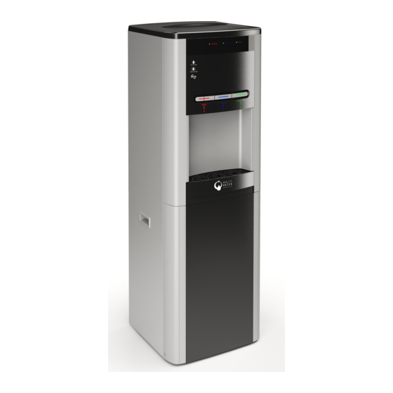
- Page 1 WL 1000 GF Technical Manual Waterlogic 1000 GF Technical Manual - Issue A, July 2011...
-
Page 2: Table Of Contents
Pre Delivery Inspection (PDI) Installation Operating Instructions Maintenance and Service Reverse Osmosis Specification Sanitization Fault Finding Technical Specifications and Warranties Electrical Schematic Diagram PCB Wetted Parts End of Life Biocote frequently asked questions Waterlogic 1000 GF Technical Manual - Issue A, July 2011... -
Page 3: Machine Overview
Watt immersed heating element. The high temperature cut out has a manual reset button, please isolate the power before resetting. The hot water tank is a sealed unit. Waterlogic 1000 GF Technical Manual - Issue A, July 2011 Waterlogic 1000 GF Technical Manual - Issue A, July 2011... - Page 4 1000 GF should not be exposed to direct sunlight. Placing the 1000GF in direct sunlight from a window, close to a radiator, or in a room of high ambient temperature, will affect the efficiency of the refrigeration circuit. Waterlogic 1000 GF Technical Manual - Issue A, July 2011...
- Page 5 Hot, Cold and Ambient IN (Water) PRESSURE VALVE INLET SOLENOID VALVE PUMP RESERVOIR AMBIENT WATER OUT HOT WATER OUT WASTE WATER CONTROLLER COLD WATER OUT COLD TANK TANK COMPRESSOR FILTER DRYER Waterlogic 1000 GF Technical Manual - Issue A, July 2011...
-
Page 6: Main Parts Layout
Hot water push button GF Back panel access to electrical service Hot safety push button Drip tray insert panel Cold Water Drain Drip tray grill Hot Water Drain Drip tray body Heater/Comp Switch Waterlogic 1000 GF Technical Manual - Issue A, July 2011... - Page 7 80 PL-1261 Water Inlet Port to tank 41 40 42 ST-8206A RO BKT Silicon Seal of Water 81 PU-4109 43 RO-0023 Inline RO 50GPD Micro filter Inlet Port 44 RO-012 Adapter Waterlogic 1000 GF Technical Manual - Issue A, July 2011...
- Page 8 Sub PCB Cover Reservoir Reservoir Seal Silicon Electrical water Level Control Carbon Air Filter Cap Reservoir Cover Mechanical Water Level Control Main PCB Ambient Water Faucet Cold Water Faucet Hot Water faucet Waterlogic 1000 GF Technical Manual - Issue A, July 2011...
- Page 9 RO membrane are located correctly. 21. Waterlogic recommends that all units are fully electrically safety tested (PAT) on site by the commissioning engineer as damage may have occurred during transit 7.
-
Page 10: Installation
8. Check the electrical wall socket (polarity) and then make the electrical connec- tion to the WL 1000 GF by plugging the power lead in to the socket on the rear of This procedure should only be carried out by a technician trained by waterlogic the WL 1000 GF. -
Page 11: Operating Instructions
6 months. There are 3 faucet points on the 1000 GF. The cup must be placed under • The UV lamp on the WL 1000 GF must be changed every 6 months. the correct faucet before pushing the coloured dispensing button. -
Page 12: Maintenance And Servicing
• No paperwork or cleaning records should ever be stored inside the 1000GF. 1. Isolate the power to the WL 1000 GF by turning off the green and red switches at the rear of the WL 1000 GF and by removing the power cord. - Page 13 Then flush the hot tank to ensure it is full of water and then turn on the red switch at the rear of the WL 1000 GF. The unit will now heat and cool. 15. Replace the top cover and lower front panel and wipe the outside surfaces (nonabrasive cleaner), and clean the drip tray.
-
Page 14: Fault Finding
8. Replace the top header tank cover, the machine top cover and the machine front lower panel. 7. Bad or plastic taste: If the WL 1000 GF is new it may need flushing for a longer period. 9. Clean all outside surfaces of the machine, including the front water dispensing area. -
Page 15: Technical Specifications And Warranties
• Adoption and use of unapproved spare parts • Engagement of untrained personnel Waterlogic has a policy of constant and continual improvement and therefore reserves the right to change specifications without prior notice, other than in the case of significant changes. -
Page 16: Wetted Parts
Controller with Wire (F121- BH1-025) PP Straight Connector for 24 PU-4101 Silicon Pipe 45 PU-4097 Floater ass'y on Gravity Fed 25 PU-4126KR DeaMyung PE 1/2"Pipe Reservoir Cover Seal 46 PU-4099 (Silicon) WITH BIOCOTE Waterlogic 1000 GF Technical Manual - Issue A, July 2011... -
Page 17: Waterlogic 1000 Gf Technical Manual - Issue A, July
ROHS Please note: All Waterlogic machines comply with EC Directive (2002/95/EC) on the Restriction BioCote® is an additional line of defence to protect between cleaning routines, it is of the Use of Certain Hazardous Substances in Electrical and Electrical Equipment not a replacement for your normal cleaning and sanitisation processes. - Page 18 Speak to a Water Expert USA, Canada and Mexico exportsales@waterlogic.com info@waterlogicusa.com + 353 1 293 1960 + 1 402 884 7212 WLI Trading Ltd. Waterlogic USA, 4141 N. 156th Street, Suite 4, 2nd Floor Beacon Court, Omaha, NE 68116 Sandyford, Dublin 18, Ireland www.waterlogic.com...
Need help?
Do you have a question about the WL 1000 GF and is the answer not in the manual?
Questions and answers