WaterLogic WL200 Operating, Installation And Service Manual
Hide thumbs
Also See for WL200:
- Manual (48 pages) ,
- Installation procedures manual (8 pages) ,
- Troubleshooting (2 pages)

Related Manuals for WaterLogic WL200


Summary of Contents for WaterLogic WL200
- Page 1 WL200 OPERATING, INSTALLATION, AND SERVICE MANUAL Waterlogic Commercial Products, LLC 11710 Stonegate Circle Omaha, NE 68164 (800) 288-1891 www.waterlogic.us Tech Portal Website: http://techportal.waterlogic.com...
-
Page 2: Table Of Contents
Model and Part Designations ............ 7 Specifications ................ 7 Operating Instructions .............. 8 Flow Diagrams ................ 9 Adjusting Cold Set Point ............ 11 Pre‐Installation Procedures ............ 12 Draining Procedures.............. 15 Installation Procedures ............. 18 Service Requirements ............... 20 Counter Top Drawings and Parts List…………………… .... 21 Tower Drawings and Parts Lists .......... 26 Electrical Diagrams .............. 31 Troubleshooting ................ 34 Warranty .................. 41 WL200 Operating, Installation, and Service Manual Page 2 ‐ Revision: 4‐13‐2016 ... -
Page 3: Features And Benefits
WL200 FEATURES AND BENEFITS Cold Water Waterlogic WL200 comes standard with Cold Water Selection. High Volume Storage and Water Capacity Tower Model has 4 liters of Cold Water Capacity. Counter Top has 2 liters of Cold Water Capacity. BioCote®Anti‐Microbial Protection Plastic surfaces surrounding dispensing areas and drip tray are infused with an exclusive silver additive called BioCote®. Silver is a natural anti‐microbial that inhibits the growth of microorganisms providing additional surface protection. Large Dispense Area with Recessed Faucet 8.5 inch dispense height with BioCote® recessed faucet to protect from cross‐contamination. WL200 Operating, Installation, and Service Manual Page 3 ‐ Revision: 4‐13‐2016 ... -
Page 4: Certifications
WL200 CERTIFICATIONS Waterlogic water treatment systems have been tested, and certified to rigorous NSF and UL Standards. We believe that performance testing and certifications validate Waterlogic as a world‐ leader in water treatment systems. WL200 Certifications Include UL399 – Certified Drinking Water Cooler Intertek Labs (ETL) Certified the WL200 to ANSI/UL 399 Standard for Drinking Water Coolers. BPA Free ‐ Waterlogic tests for BPA and declares that all of its products are Bisphenol‐A FREE and contain no harmful BPA plastics. Waterlogic manufacturing is certified to ISO 9001 – Quality Management Systems (certified by Moody International). ISO 9001 is the internationally accepted standard for well managed organizations that have adopted the key quality management principles to its operations to bring consistent quality products and a culture of continuous improvement. Safe Drinking Water Act Waterlogic water treatment systems conform to the Safe Drinking Water Act (SWDA) “lead‐free” amendment effective January 4, 2014. WL200 Operating, Installation, and Service Manual Page 4 ‐ Revision: 4‐13‐2016 ... - Page 5 Waterlogic and Authorized Waterlogic Dealers employ trained service personnel who are experienced in the installation, function and repair of Waterlogic equipment. This publication is written for use by these qualified individuals. Waterlogic encourages users to learn about products, however, we believe that product knowledge and service is best obtained by consulting Waterlogic or an Authorized Waterlogic Dealer. Waterlogic water treatment systems should be combined with selected water treatment components to create a system specifically tailored for each application by trained and qualified personnel. Products manufactured and marketed by Waterlogic and its affiliates are protected by patents issued or pending in the United States and other countries. Waterlogic reserves the right to change the specifications referred to in this literature at any time, without prior notice. Changes or modifications not expressly approved by Waterlogic could void the warranty and user’s authority to operate the equipment. SAFETY ALERT SYMBOLS Read and follow all safety information carefully. The signal words used in this manual are selected as shown below and based on an assessment of the degree of potential injury or damage (severe or minor) and the occurrence of injury (definitely occurs or has the potential to occur) when the warning is ignored: DANGER! Indicates a situation which, when not avoided, results in death or severe injury. WARNING! Indicates a situation which, when not avoided, has the potential to result in death or severe injury; and/or severe property damage. CAUTION! Indicates a situation which, when not avoided, results or has the potential to result in minor injury; and/or minor property damage. WL200 Operating, Installation, and Service Manual Page 5 ‐ Revision: 4‐13‐2016 ...
-
Page 6: Safety Precautions
SAFETY PRECAUTIONS Basic safety precautions should be followed, including the following: DANGER! If incorrectly installed, operated or maintained, this product can cause death or severe injury. Those who install, operate, or maintain this product should be trained in its proper use, warned of its dangers, and should read the entire manual before attempting to install, operate, or maintain this product. WARNING! Unit is to be used for its intended purpose as described in this manual, and untrained individuals who use this manual assume the risk of any resulting property damage or personal injury. DANGER! ELECTRICAL SHOCK HAZARD. Always unplug from power supply prior to servicing equipment to prevent electrical shock. WARNING! This system to be used for water only and is not intended for use where water is microbiologically unsafe or with water of unknown quality without adequate disinfection before or after the system. The system is designed for the supplemental bactericidal treatment of either treated and disinfected public drinking water, or other drinking water, which has been tested and deemed acceptable for human consumption by the state or local health agency having jurisdiction. The system is designed to reduce normally occurring non‐pathogenic or nuisance microorganisms only. System is not intended for treatment of contaminated water. WARNING! Dispenser Could Tip or Fall causing serious injury. Always install unit on a firm, flat, and level surface and secure the WL200 to the base cabinet with the screw provided to lock the components together. Never place heavy items on top of unit and never climb, stand, or hang on unit or storage cabinet to prevent injury and damage. CAUTION! INDOOR USE ONLY. Do not install outdoors or where unit is in direct sunlight. Do not install where ambient temperature goes below 50F or above 97F. Avoid high humidity and moisture. Product life and performance will be impacted and warranty could be voided. WL200 Operating, Installation, and Service Manual Page 6 ‐ Revision: 4‐13‐2016 ... -
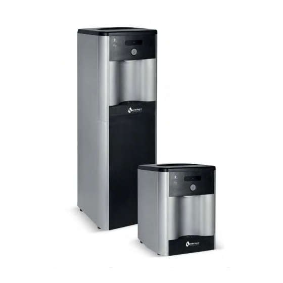
Page 7: Model And Part Designations
R134a Pressures High (230 psi), Low (90 psi) SHIPPING SPECIFICATIONS ITEM WL200 Counter Top WL200 Tower 13.5” x 14.5” x 17.75” (34cm x 37cm x 13.5” x 14.5 x 40.5” (34cm x 41cm x Width/Depth/Height 45cm) 103cm) Weight (dry) 42 pounds (19.5 kg) 58 pounds (26.5 kg) ELECTRICAL SPECIFICATIONS ELECTRICAL SUPPLY 120V/60Hz, 1PH 15 Amp Service COMPONENT POWER (approximate) AMP DRAW (approximate) Compressor 216 1.8 Amps WL200 TOTAL 216 1.8 Amps #WL200 Counter Top is 17.75 in. tall and may not fit between Counter Tops and cabinets ‐ Check installation to ensure adequate clearance. WL200 Operating, Installation, and Service Manual Page 7 ‐ Revision: 4‐13‐2016 ... -
Page 8: Operating Instructions
OPERATING INSTRUCTIONS Dispensing Button The above picture shows front LCD display and control panel for the Waterlogic WL200. For Cold Water: Press the Dispensing Button. WL200 Operating, Installation, and Service Manual Page 8 ‐ Revision: 4‐13‐2016 ... -
Page 9: Flow Diagrams
WL200 COUNTER TOP WATER FLOW DIAGRAM WL200 Operating, Installation, and Service Manual Page 9 ‐ Revision: 4‐13‐2016 ... - Page 10 WL200 TOWER WATER FLOW DIAGRAM Water In Solenoid Valve Condenser Filter Dryer Compressor WL200 Operating, Installation, and Service Manual Page 10 ‐ Revision: 4‐13‐2016 ...
-
Page 11: Adjusting Cold Set Point
ADJUSTING COLD SET POINT The cold set point can be adjusted by accessing the cold thermostat adjustment screw Under the Decal at the rear of the unit. This will NOT Void the Warranty as the current Decal states on the back of the unit. The factory set point is ~41°F and is indicated by the dot on sheet metal around the adjustment screw and behind the decal. Turning the adjustment screw clockwise lowers the set point temperature and the range is approximately 20°F thru the full range of adjustment (~7:00 to the ~5:00 positions). You should be able to turn the screw from the factory set point of 41°F (~12:00 position) about 45 degrees clockwise (2:30 on a clock) to reduce the set point temperature by 6°F and achieve the 35‐36°F setting you are looking for. Trial this by adjusting and then measure the water temperature 10‐15 minutes after the compressor shuts off (coldest point) to verify the set point temperature. Each unit will vary slightly. Try not to go much past the “3:00 position” to avoid freezing the cold tank as shown above. Future Production changes Cold Thermostat Cover Label to LP‐0326‐L00‐ 00 / WLUSA PN LP‐0326. WL200 Operating, Installation, and Service Manual Page 11 ‐ Revision: 4‐13‐2016 ... -
Page 12: Pre-Installation Procedures
WARNING! ALWAYS SANITIZE BEFORE USE. Sanitize before use to eliminate any potential microbiological contaminates. Materials Needed: Personal Protective Equipment. Rubber or Nitrile Safety Gloves and Protective Eyewear Phillips Screwdriver Temperature Gage Water Pitcher or Container to collect water from the faucet 5 gallon container or drain basin Sanitizer ‐ Household Bleach (5.25% Sodium Hypochlorite) or Citric Acid Based Cleaner ¼” Plastic Tubing, at least 4 feet in length, and assorted ¼” quick connect fittings TDS Meter and Test Strips for measuring chlorine ‐ Optional 1. Unpack the Waterlogic WL200 and check exterior for damage. Sanitizing Sanitize using a Household Bleach (5.25% Sodium Hypochlorite solution) or other approved cleaner throughout the cold and sparkling water circuits. Follow all instructions on the sanitizer and flush with fresh water through the faucet until odor and taste is acceptable. WARNING! USE PROPER PERSONAL PROTECTIVE EQUIPMENT Always ensure proper ventilation and use proper personal protective equipment such as gloves and eye protection when using chemicals. Refer to Material Safety Data Sheet for specific requirements of each chemical product. Take all necessary precautions to prevent sanitizer from contacting eyes, clothing, and any other surfaces in could damage (carpets). ... - Page 13 6. Turn off water supply and remove Sanitizing Cartridge from inlet water supply. Reconnect water supply to inlet bulkhead fitting. Flush Filters CAUTION! FILTER FLUSH REQUIRED. WL200’s are not supplied with filters. Filters should be configured to optimize your system. Filters need to be configured and specified to do the job given the local water conditions, usage, maintenance schedule, and placement restrictions. In order for the filters to perform as represented and to provide the best quality water possible, it is essential that filters be replaced periodically. The frequency of filter changes depends upon your water quality and your water usage. For example, if there is a lot of sediment and/or particles in your water, then you will have to change your filters more frequently than a location with little to no sediment. Be sure to replace your filters whenever you notice a decline in the performance, whether it is a drop in flow rate and/or pressure or an unusual taste in the water. 7. Flush thoroughly per filter manufacturers’ recommendation with fresh water to drain. 8. Once flushed, install the filters. Following the flow direction on the filter. NOTE: Filters should not be flushed prior to 24 hours before installation to limit Microbial Growth. 9. Connect WL200 to power. WL200 Operating, Installation, and Service Manual Page 13 ‐ Revision: 4‐13‐2016 ...
- Page 14 Flushing the Sanitizer from the Machine 10. Place a pitcher, catch basin, or other container under the faucet of the WL200. 11. Flush the Cold Tank. Run several gallons of water through the faucet by dispensing cold water to dilute and remove the sanitizer from the cold circuit. You can use chlorine test strips to evaluate the water. 12. Once the sanitizer odor/taste has been flushed out of the cold side of the machine the sanitization process for the Cold Circuit is now complete. WL200 Operating, Installation, and Service Manual Page 14 ‐ Revision: 4‐13‐2016 ...
- Page 15 Draining Notes Drain the WL200 for transportation. WARNING! STORE UNIT EMPTY. ALWAYS SANITIZE BEFORE REUSE. The unit must be completely drained and sealed before storing to avoid stagnation and reduce microbial growth). Disable Cold Tank 1. Turn off the Red Power Switch to disable compressor. O = OFF Turn off Water Supply and Bleed Water Pressure 2. Isolate the unit from feed water by turning off the supply. 3. Dispense cold still water to relieve any pressure built up in the system. 4. Remove the water supply line from the inlet line bulkhead fitting at back of machine. 5. Install dust cap or plug into water supply line bulkhead fitting. Drain the Cold Water Tank and Circuit 6. Remove top cover. 7. Remove front panel. Remove 2 Phillip screws securing front panel. Unseat faucet assembly from panel. Unclip wires from PCB. WL200 Operating, Installation, and Service Manual Page 15 ‐ Revision: 4‐13‐2016 ...
- Page 16 8. Disconnect tubing from inlet elbow from solenoid and allow water to drain. 9. Reconnect tubing into inlet elbow, 10. Dry inside of unit. 11. Replace front panel. WL200 Operating, Installation, and Service Manual Page 16 ‐ Revision: 4‐13‐2016 ...
- Page 17 1. Turn off the Red Power Switch to disable the compressor. O = OFF Turn off Water Supply and Bleed Water Pressure 2. Isolate the unit from feed water by turning off the supply. 3. Dispense cold still water to relieve any pressure built up in the system. 4. Remove the water supply line from the inlet line bulkhead fitting at back of machine. 5. Install dust cap or plug into water supply line bulkhead fitting. Drain the Cold Water Tank and Circuit 6. Remove lower front panel to access tank feed lines. 7. Disconnect tank line feed line from cold inlet solenoid to drain into basin or catch. 8. Reconnect tubing into inlet elbow once drained. 9. Dry inside of unit if necessary. 10. Replace lower front panel. WL200 Operating, Installation, and Service Manual Page 17 ‐ Revision: 4‐13‐2016 ...
-
Page 18: Installation Procedures
WARNING! USE ONLY Waterlogic SUPPLIED POWER CORD. Locate system within 5 feet of power supply. Never use an extension cord or adapter. Do not use a damaged power cord or plug. Keep power cord out of heavy traffic areas and away from heat sources. Do not, under any circumstances, remove ground prong or alter the power cord. Never pull the power plug from the outlet with a wet hand or allow the plug to get wet. Failure to use the supplied power cord will void UL Certification and Warranty. CAUTION! INDOOR USE ONLY. Never expose to direct sunlight, heat sources, or ambient air temperature above 100°F (37°C) or below 35°F (2°C). Install indoors and keep unit away from excessive humidity. Never expose to freezing temperatures. Ensure there is adequate clearance around the unit to allow refrigeration system condenser to dissipate heat. Warmer environments require more clearance around the unit. Minimum clearance around all surfaces of the machine is 2‐ inches. Installs where the ambient temperature exceed 80F, require a minimum of 4‐inches clearance for proper heat dissipation and efficient operation. CAUTION! USE A WATER PRESSURE REGULATOR. Waterlogic will not be responsible for injury or damage caused by excessive water pressure. Operating pressure must be 40 psi to 60 psi. Be aware any of potential pressure surges caused by building/municipal pumping stations. CAUTION! USE UV STABILIZED SUPPLY LINES. Feed the unit with a potable ambient or cold water supply only. Feed water over 100° F (37°C) can damage the treatment components. Water block devices and external leak detectors are strongly recommended. Locate the unit as close to the water supply and the electrical connections as possible. WARNING! STORE AND TRANSPORT UNIT EMPTY. ALWAYS SANITIZE BEFORE USE. The unit must be completely drained and sealed before storing to avoid stagnation and reduce microbiological contamination (potential bacterial growth). Sanitize before use to eliminate any potential microbiological contaminates Pre‐installation and sanitization procedures as prescribed in this manual must be performed before installing the WL200. Always install indoors and place the Waterlogic WL200 on a firm, flat and stable surface. WL200 Operating, Installation, and Service Manual Page 18 ‐ Revision: 4‐13‐2016 ... - Page 19 1. Attach the water supply line to the 1/4” feed water inlet bulkhead fitting on the back of the unit. Waterlogic requires the use of a water pressure regulator. Water feed pressure must be between 40‐60 psi. Turn on the water supply and check for leaks. 2. Check to ensure that the Red Power Switch is off. O=OFF 3. Connect the power cord to the back of the Waterlogic WL200 and to a 120 Volt supply. 4. Fill the Cold Tank. Hold a container under the dispensing faucet, press and hold the main dispensing button until a continuous flow of water is obtained. Once a continuous flow is obtained, release the dispensing button. Cold tank is now full. 5. Move the Waterlogic WL200 into its final operating position. Be sure that a minimum of 2” clearance is maintained around both the sides and the back of the unit. This is important to allow proper airflow and heat exchange of refrigeration system. 6. Level unit using the adjustable feet to level if necessary. Never install on incline. 7. Turn the Red Power Switch on. I=ON. ...
-
Page 20: Service Requirements
SERVICE REQUIREMENTS WARNING! Read and understand the contents of this manual before attempting to service WL200. Failure to follow the instructions in this manual could result in death, serious personal injury, or severe property damage. Only trained and qualified technicians should attempt to install, maintain, or service Waterlogic Equipment. 1. Visually inspect all electrical and water connections for signs of wear or damage. DANGER! HIGH VOLTAGE ELECTRICAL HAZARD. Unplug before inspection and service. 2. Ensure there is adequate (minimum of 2”) clearance around the unit and clean the condenser grill and compressor fan to provide efficient cooling system operation. 3. Sanitize the cold tank per instructions in the pre‐installation procedures. 4. Clean and sanitize external surfaces of the unit. Use soap and water or chemicals that are compatible with ABS plastic and will not damage or degrade the product surfaces. 5. Remove and clean the Faucet. Replace as needed. WARNING! SANITIZER MAY CONTAIN HAZARDOUS CHEMICALS. Use of proper personal protective equipment such as rubber gloves and eye protection is required. WL200 Operating, Installation, and Service Manual Page 20 ‐ Revision: 4‐13‐2016 ... - Page 21 WL200 COUNTER TOP DRAWINGS with PART NUMBERS Wetted Parts WL200 Operating, Installation, and Service Manual Page 21 ‐ Revision: 4‐13‐2016 ...
- Page 22 ElectroMagnetic Interference 10‐4013 Yes filter (EMI) Fuse Holder and Fuse 120V / 15A 6 EL‐5053 EL‐5053 Yes with One Wire 6.1 EL‐5010 Fuse 120V / 15A 10‐3013 Yes Red Power and Compressor 7 EL‐5019‐A 12‐5600 Yes Switch Side Panel 8 ST‐8245 12‐8062 Yes Counter Top Only Bulkhead Union ¼” x ¼” John 9 PU‐4028‐A 10‐3067 Yes Guest P/N PI1208S WL200 Operating, Installation, and Service Manual Page 22 ‐ Revision: 4‐13‐2016 ...
- Page 23 14.1 CU‐0001 Solenoid Cushion CU‐0001 Yes Leak System Inlet Solenoid Yes 15 ST‐8244 12‐3195 Bracket Filter Bracket 16 ST‐8152 12‐3175 Yes Counter Top Only 17 PL‐1012 Faucet Cold only NA Yes Natural Faucet O‐Ring – Silicon 17.1 CT‐2007 10‐2600 Yes White WL200 Operating, Installation, and Service Manual Page 23 ‐ Revision: 4‐13‐2016 ...
- Page 24 Charcoal 23 LP‐7085 Button Label Cold only 12‐8610 Yes 24 PL‐1152 Drip Tray Grill ‐ Charcoal 12‐8150 Yes Drip Tray ‐ Charcoal with 25 PL‐1156 12‐8055 Yes Waterlogic Logo Included with CT‐ UV Lamp Fixing Rubber (Silicon) 26 CT‐2001‐B 10‐8085 2062‐CN Counter Top Only Quartz Sleeve UV Lamp Retaining Threaded Nut 27 PL‐1128 12‐1210 Yes Counter Top Only WL200 Operating, Installation, and Service Manual Page 24 ‐ Revision: 4‐13‐2016 ...
- Page 25 33.1 EN‐6059 PCB Stand‐off Pin 10‐3017 Yes 5/16” x ¼” Reducing Elbow John Purchase from 34 PU‐4007‐A No Guest P/N PI211008S John Guest Wire Condenser Special 35 CO‐9031 12‐3100 Counter Top Only Order JG LLD PE Tube ‐ Blue Purchase from 36 PU‐4031‐A O.D.1/4"John Guest P/N PE‐08‐ No John Guest BI‐1000F‐B Not EL‐5001‐B Power Cord – 120V 10‐3007 Yes Shown WL200 Operating, Installation, and Service Manual Page 25 ‐ Revision: 4‐13‐2016 ...
- Page 26 WL200 TOWER DRAWINGS with PART NUMBERS Wetted Parts WL200 Operating, Installation, and Service Manual Page 26 ‐ Revision: 4‐13‐2016 ...
- Page 27 6 ST‐8135 12‐8002 No Tower Only Silver Side Panel with Hole for 7 ST‐8157 Handle 12‐8000 Yes Tower Only 8 PL‐1123 Side Panel Plastic Handle 12‐8058 Yes Bulkhead Union ¼” x ¼” John 9 PU‐4028‐A 10‐3067 Yes Guest P/N PI1208S Compressor (R134a 1/8HP) 10 CO‐9001‐A 10‐2200 Yes 120V/60Hz WL200 Operating, Installation, and Service Manual Page 27 ‐ Revision: 4‐13‐2016 ...
- Page 28 5/16” x ¼” Reducing Elbow John Purchase from 15 PU‐4007‐A No Guest P/N PI211008S John Guest Filter Bracket 16 ST‐8138 12‐8005 Yes Tower Only Front Lower Panel 17 PL‐1148 12‐8052 Yes Tower Only Front Lower Insert Panel 18 PL‐1149 10‐8053 Yes Tower Only 19 PL‐1012 Faucet Cold only NA No WL200 Operating, Installation, and Service Manual Page 28 ‐ Revision: 4‐13‐2016 ...
- Page 29 23 PL‐1100 12‐8600 Yes only Front Upper Insert Panel ‐ 24 PL‐0084‐L00‐CL NA No Charcoal 25 LP‐7085 Button Label Cold only 12‐8610 Yes 26 PL‐1152 Drip Tray Grill ‐ Charcoal 12‐8150 Yes Drip Tray ‐ Charcoal with 27 PL‐1156 12‐8055 Yes Waterlogic Logo WL200 Operating, Installation, and Service Manual Page 29 ‐ Revision: 4‐13‐2016 ...
- Page 30 Upper Shelf 31 ST‐8136‐R2 12‐8003 Yes Tower Only Wire Condenser Special 32 CO‐9027 12‐8102 Tower Only Order JG LLD PE Tube ‐ Blue Purchase from 33 PU‐4031‐A O.D.1/4"John Guest P/N PE‐08‐ No John Guest BI‐1000F‐B Not EL‐5001‐B Power Cord – 120V 10‐3007 Yes Shown WL200 Operating, Installation, and Service Manual Page 30 ‐ Revision: 4‐13‐2016 ...
-
Page 31: Electrical Diagrams
WL200 COUNTER TOP ELECTRICAL DIAGRAM DANGER! HIGH VOLTAGE ELECTRICAL HAZARD. PCB (Printed Circuit Board) contains High Voltage. Only trained and qualified technicians should attempt live testing. WL200 Operating, Installation, and Service Manual Page 31 ‐ Revision: 4‐13‐2016 ... - Page 32 WL200 TOWER ELECTRICAL DIAGRAM DANGER! HIGH VOLTAGE ELECTRICAL HAZARD. PCB (Printed Circuit Board) contains High Voltage. Only trained and qualified technicians should attempt live testing. WL200 Operating, Installation, and Service Manual Page 32 ‐ Revision: 4‐13‐2016 ...
- Page 33 Cold Water is not Cold (41° +/‐ 5° F) Possible Reason Solution Check that the Red Power and Compressor switch is on. No power or refrigeration elements Turn Red Power and Compressor Switch on. I = ON Tank has run out of cold water. Wait for cold tank to chill water to temperature prior to dispensing more cold water. Cold tank capacity is 4 liters for Tower and 2 liters for Counter A greater capacity of Waterlogic Water Systems is available. Top. Check continuity of thermostat with multimeter. Replace Cold Water Thermostat thermostat as required. Run compressor for at least ten minutes. If condenser is not Refrigerant has run out warm then refill the refrigerant. If compressor is not running, repair or replacement is Compressor problem needed. WL200 Operating, Installation, and Service Manual Page 33 ‐ Revision: 4‐13‐2016 ...
-
Page 34: Troubleshooting
3. Compressor is Not Running Red Power Switch is lit but the Red LED on the Front is not lit Possible Reason Solution Bad Transformer Replace Transformer Black Power Connector to the Properly connect. PCB is not properly connected Replace Front PCB Bad Front PCB Part Number: EN‐6086 / Waterlogic P/N 12‐8615. Defective Red Power / Replace Power Heater / Compressor Switch Compressor Switch Compressor Runs But Does Not Chill Possible Reason Solution Condenser is dirty Clean the condensing coil of any obstructions or dust. Make sure unit is not under minimum ventilation requirements (2 Reduction of airflow into unit. to 4 inches). Compressor is running very Low or lost refrigerant. Refrigerant recharge required. hot. WL200 Operating, Installation, and Service Manual Page 34 ‐ Revision: 4‐13‐2016 ... - Page 35 Compressor is Not Running Possible Reason Solution Red Power and Compressor Turn Red Power and Compressor Switch on. Switch button on unit is in the I = ON off position Turn Red Power and Compressor Switch off. O = OFF. Remove the compressor cap on side of the compressor; Disconnect the black and red terminal connectors; Compressor Starting Circuit Inspect the starter and overload relay for any defects. Replace components(s) as needed. Turn Red Power and Compressor Switch on I = ON and retest compressor operation. WL200 Operating, Installation, and Service Manual Page 35 ‐ Revision: 4‐13‐2016 ...
- Page 36 5. Cold Water dispenses from Faucet and Vent Outlet Simultaneously 6. Small amount of water periodically dispenses from faucet automatically 7. Dispense Buttons Stick 8. Run-On - Water continues to dispense out of faucet after releasing the dispense button WL200 Operating, Installation, and Service Manual Page 36 ‐ Revision: 4‐13‐2016 ...
- Page 37 WL250 to operate properly. pressure to the unit? Listen for solenoid to activate, not button “click”. Adjust water pressure to 40‐60 psi. Loose or bad connection on the Front Dispensing PCGB or Check that they are connected properly and tightened. Solenoid Connector If both the Water Pressure and PCB have been ruled out, then it is the Solenoid. Solenoid Replace Solenoid. Dispensing button is broken on Check PCB for loose or damaged button. Replace PCB as PCB necessary. Dispensing Won’t Stop when Not Holding the Dispensing Button Possible Reason Solution Replace Front PCB Bad Display PCB Hot and Cold – P/N EN‐6085 WLUSA PN 12‐8103 Cold Only – P/N EN‐6086 WLUSA PN 12‐8615 Debris in the Solenoid Inspect Solenoid for debris and clean out as needed. Dirt or Foreign material is filling the gap around the push‐buttons. Dispensing Button Stuck Inspect the push buttons and clean surrounding area. Inspect faucet assembly inside the unit and clean as necessary. WL200 Operating, Installation, and Service Manual Page 37 ‐ Revision: 4‐13‐2016 ...
- Page 38 Closed water supply valve Open the water supply valve. The unit is not properly Check electrical outlet connection, or for blown circuit plugged into electrical outlet breaker. Red Power and Compressor Turn Red Power and Compressor switch on. Switch on unit is in the off I = ON position 15 Amp Fuse Blown Replace the 15 Amp Fuse as needed. Water is present in the bottom tray, causing the leak detection to trigger. Remove the Top Cover and Front Panel. Tip the unit slightly to drain, dry bottom tray completely. *Leak Detection is on the Counter Top Model only. Turn power off; unplug the unit and visually inspect solenoid connections into the Display PCB. Verify the soldering points Cold Solenoid connections into on connections are secure into the board. the Display PCB are loose. Remove the PCB to inspect the front of the board. Exhausted Filter Replace filters as needed. WL200 Operating, Installation, and Service Manual Page 38 ‐ Revision: 4‐13‐2016 ...
- Page 39 Replace Cold Tank. Tank is not sealed properly. Small Amount of Water Periodically Dispenses from Faucet Automatically Possible Reason Solution Cold or Hot Water solenoid Inspect valve components for proper function. Replace as valve malfunction necessary. Pre‐determine whether water being dispensed is hot / cold. Isolate the water supply; push the DISPENSE button to Obstruction in solenoid release the line pressure, and remove the coil affixed to the housing is preventing proper solenoid stem. sealing of component. Remove the stem from the solenoid housing and allow water from the tank to flush out the contaminant(s). Dispense Buttons Stick Possible Reason Solution Dirt or Foreign material is Inspect the push buttons and clean surrounding area. filling the gap around the Inspect faucet assembly inside the unit and clean as push‐buttons. necessary. WL200 Operating, Installation, and Service Manual Page 39 ‐ Revision: 4‐13‐2016 ...
- Page 40 WLCP Lab Testing of Rn On 7‐31‐2013 Pressure Pressure Time Flow Rate Run On Static PSI Dynamic PSI 4 Liters I/min Seconds 68 40 61 2.9508197 3 50 30 72 2.5 2.5 32 20 92 1.956217 2 Pressure measured at inlet line to unit. Static with unit closed. Dynamic with unit dispensing cold water. No filters were installed in unit. WL200 Operating, Installation, and Service Manual Page 40 ‐ Revision: 4‐13‐2016 ...
-
Page 41: Warranty
Return Authorization which you must obtain prior to shipping the product. You are responsible for the cost of freight in to Waterlogic. Waterlogic and its affiliated companies hereby limit the duration of any and all implied warranties to a maximum period of three (3) years from the date of purchase including, but not limited to, the implied warranties of merchantability and fitness for a particular purpose. Some states do not allow limitations on how long an implied warranty lasts, so the above limitation may not apply to you. Consequential and incidental damages are not recoverable under this warranty. Some states do not allow the exclusion or limitation of incidental or consequential damages, so the above limitation or exclusion may not apply to you. This warranty gives you specific legal rights and you may also have other rights which may vary from state to state. New Warranty Policy issued by Waterlogic Commercial Products LLC, USA ‐ January 10, 2014 Waterlogic Commercials Products LLC Tel: (800) 288‐1891 11710 Stonegate Circle Website: waterlogic.us Omaha, NE 68164 WL200 Operating, Installation, and Service Manual Page 41 ‐ Revision: 4‐13‐2016 ...
Need help?
Do you have a question about the WL200 and is the answer not in the manual?
Questions and answers