Table of Contents
Advertisement
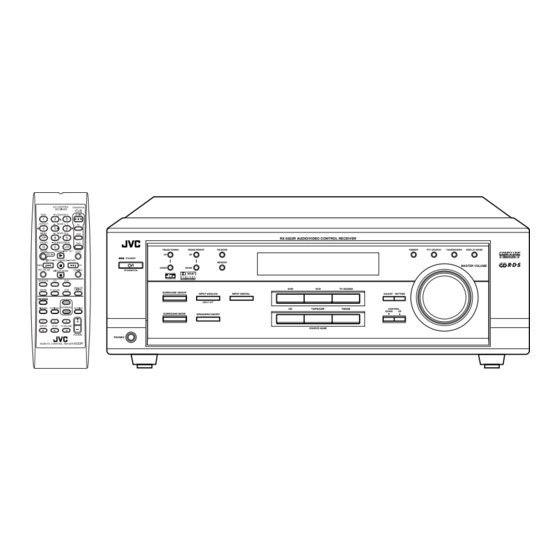
AUDIO/VIDEO CONTROL RECEIVER
RX-5022RSL
FM/AM TUNING
UP
STANDBY
DOWN
STANDBY/ON
SURROUND ON/OFF
FM MODE
SURROUND MODE
PHONES
RX-5022R AUDIO/VIDEO CONTROL RECEIVER
FM/AM PRESET
FM MODE
UP
MEMORY
DOWN
DVD
VCR
INPUT ANALOG
INPUT DIGITAL
INPUT ATT
CD
TAPE/CDR
SPEAKERS ON/OFF
SOURCE NAME
INSTRUCTIONS
DIMMER
PTY SEARCH
TA/NEWS/INFO
DISPLAY MODE
MASTER VOLUME
TV SOUND
ADJUST
SETTING
FM/AM
CONTROL
DOWN
UP
For Customer Use:
Enter below the Model No. and Serial
No. which are located either on the rear,
bottom or side of the cabinet. Retain this
information for future reference.
Model No.
Serial No.
LVT0850-008A
[B]
Advertisement
Table of Contents

Related Manuals for JVC RX-5022RSL


Summary of Contents for JVC RX-5022RSL
- Page 1 AUDIO/VIDEO CONTROL RECEIVER RX-5022RSL RX-5022R AUDIO/VIDEO CONTROL RECEIVER FM/AM TUNING FM/AM PRESET FM MODE DIMMER PTY SEARCH TA/NEWS/INFO DISPLAY MODE STANDBY MEMORY MASTER VOLUME DOWN DOWN STANDBY/ON TV SOUND SURROUND ON/OFF INPUT ANALOG INPUT DIGITAL ADJUST SETTING FM MODE INPUT ATT...
- Page 2 Warnings, Cautions and Others IMPORTANT for the U.K. DO NOT cut off the mains plug from this equipment. If the plug fitted is not suitable for the power points in your home or the cable is too short to reach a power point, then obtain an appropriate safety approved extension lead or consult your dealer.
-
Page 3: Safety Instructions
No obstructions in 15 cm from the back Bottom: No obstructions, place on the level surface. In addition, maintain the best possible air circulation as illustrated. Spacing 15 cm or more RX-5022RSL Front Wall or obstructions Stand height 15 cm or more Floor... -
Page 4: Table Of Contents
Using Dolby Pro Logic II, Dolby Digital and DTS Digital Surround ............24 Using DAP Modes and All Channel Stereo ......26 COMPU LINK Remote Control System ..27 Operating JVC's Audio/Video Components .......... 28 Operating Audio Components ..........28 Operating Video Components ..........30 Troubleshooting ......... -
Page 5: Parts Identification
Parts Identification Front Panel RX-5022R AUDIO/VIDEO CONTROL RECEIVER FM/AM TUNING FM/AM PRESET FM MODE DIMMER TA/NEWS/INFO DISPLAY MODE PTY SEARCH ANALOG TUNED STEREO AUTO MUTING SLEEP STANDBY PRO LOGIC ΙΙ DSP H.PHONE DIGITAL AUTO INPUT ATT TA NEWS INFO VOLUME MEMORY LINEAR PCM S.WFR... -
Page 6: Getting Started
Getting Started Putting Batteries in the Remote Control Before Installation General Precautions Before using the remote control, put two supplied batteries first. • When using the remote control, aim the remote control directly at • DO NOT insert any metal object into the unit. the remote sensor on the unit. -
Page 7: Connecting The Fm And Am (Mw/Lw) Antennas
Connecting the FM and AM (MW/LW) Antennas AM (MW/LW) Loop Antenna Outdoor FM antenna (not supplied) (supplied) If FM reception is poor, connect outdoor FM antenna. IA L IA L Standard type Supplied FM outdoor FM antenna antenna ANTENNA (IEC or DIN45325) (not supplied) FM 75 COAXIAL... -
Page 8: Connecting The Speakers
Getting Started Speaker layout diagram Connecting the Speakers “NO” for the subwoofer, “LARGE” for the front speakers, After connecting the front, center, rear speakers and/or a subwoofer, and “SMALL” for the center and rear speakers are initial set the speaker setting information properly to obtain the best settings. -
Page 9: Connecting Audio/Video Components
Cassette deck or CD recorder Connecting Audio/Video Components Cassette deck Turn off all components before connections. To audio output To audio input PHONO You can connect the following audio/video components to this receiver. Refer also to the manuals supplied with your components. Audio Components Video Components •... -
Page 10: Connecting The Power Cord
Getting Started IMPORTANT: • When connecting the DVD player or digital TV using the digital terminal, you also need to connect it to the video jack on the rear. Without connecting it to the video jack, you can view no playback picture. -
Page 11: Basic Operations
Basic Operations Front Panel Remote Control Display STANDBY lamp DIMMER A/V CONTROL STANDBY/ON RECEIVER STANDBY/ TEST CENTER AUDIO EFFECT REAR L RX-5022R AUDIO/VIDEO CONTROL RECEIVER MENU REAR R AUDIO FM/AM TUNING FM/AM PRESET FM MODE DIMMER PTY SEARCH TA/NEWS/INFO DISPLAY MODE ENTER SUBWOOFER ANALOG... -
Page 12: Adjusting The Volume
Basic Operations Selecting different sources for picture and Listening Only with Headphones sound You can watch picture from a video component while listening to You must turn off the speakers when you listen with headphones. sound from another component. Connect a pair of headphones to the PHONES jack on the front Press one of the audio source selecting buttons (CD, TAPE/CDR, panel. -
Page 13: Turning Off The Sounds Temporarily-Muting
Basic adjustment auto memory Turning Off the Sounds Remote This receiver memorizes sound settings for each source when: ONLY Temporarily—Muting • you turn off the power, • you change the source, and Press MUTING on the remote control to mute MUTING •... -
Page 14: Basic Settings
Basic Settings Front Panel Remote Control Display A/V CONTROL STANDBY/ON RECEIVER TEST CENTER AUDIO EFFECT REAR L RX-5022R AUDIO/VIDEO CONTROL RECEIVER MENU REAR R FM/AM TUNING FM/AM PRESET FM MODE PTY SEARCH TA/NEWS/INFO DISPLAY MODE DIMMER ENTER SUBWOOFER ANALOG TUNED STEREO AUTO MUTING SLEEP STANDBY... -
Page 15: Setting The Speaker Information
Remote Setting the Speaker Information DIGITAL AUTO : Select this for the digital input mode. The receiver automatically detects the incoming signal format. (The DIGITAL To obtain the best possible sound or effect from the Surround modes AUTO indicator lights up on the display, (see page 18), register the following speakers and subwoofer then the digital signal indicator for the information after all connections are completed. - Page 16 Basic Settings Speaker size Speaker distance Register the unit you use, then the speaker distance from your Register the sizes of all the connected speakers. • When you change your speakers, register the information about listening point. • If you have set the unit before, start from step 3 . the speakers again.
- Page 17 Low frequency effect attenuator Crossover frequency Small speakers cannot reproduce the bass sounds efficiently. If you If the bass sound is distorted while playing back software using Dolby Digital or DTS Digital Surround, follow the procedure use a small speaker in any position, this receiver automatically reallocates the bass sound elements assigned to the small speaker to below: •...
-
Page 18: Sound Adjustments
Sound Adjustments Front Panel Remote Control Display A/V CONTROL STANDBY/ON RECEIVER TEST CENTER AUDIO EFFECT REAR L MENU REAR R RX-5022R AUDIO/VIDEO CONTROL RECEIVER SUBWOOFER +/– ENTER SUBWOOFER FM/AM TUNING FM/AM PRESET FM MODE DIMMER PTY SEARCH TA/NEWS/INFO DISPLAY MODE RETURN TA/NEWS/INFO 100 SLEEP... -
Page 19: Tuner Operations
Tuner Operations Front Panel Remote Control FM/AM FM/AM A/V CONTROL STANDBY/ON RECEIVER TUNING PRESET operating TEST CENTER AUDIO Display buttons UP/DOWN UP/DOWN FM MDOE EFFECT REAR L 10 keys MENU REAR R ENTER SUBWOOFER RETURN TA/NEWS/INFO SLEEP RX-5022R AUDIO/VIDEO CONTROL RECEIVER SOUND operating PTY–PTY SEARCH–PTY... -
Page 20: Selecting The Fm Reception Mode
Tuner Operations Press MEMORY again while the Selecting the FM Reception Mode MEMORY selected channel number is flashing When an FM stereo broadcast is hard to receive or noisy, you can on the display. change the FM reception mode while receiving an FM broadcast. The selected channel number stops flashing. -
Page 21: Using The Rds (Radio Data System) To Receive Fm Stations
About characters shown on the display Using the RDS (Radio Data System) to When the display shows PS, PTY, or RT signals, the following Receive FM Stations characters are used. • The display cannot show accented letters, “A,” for instance, may RDS allows FM stations to send an additional signal along with their stand for accented “A’s”... - Page 22 Tuner Operations On the front panel: PTY codes PTY SEARCH Press PTY SEARCH while listening to NONE an FM station. NEWS ALARM “PTY SELECT” flashes on the display. TEST AFFAIRS Press CONTROL UP 5/DOWN ∞ until CONTROL DOWN the PTY code you want appears on the INFO (Information) DOCUMENT display, while “PTY SELECT”...
-
Page 23: Switching To A Broadcast Program Of Your Choice Temporarily
Switching to a Broadcast Program of If the FM station you are listening to is CASE 2 Your Choice Temporarily broadcasting the program you have selected The receiver continues to receive the station, but the indicator Another convenient RDS service is called “Enhanced Other of received PTY code starts flashing. -
Page 24: Creating Realistic Sound Fields
Creating Realistic Sound Fields Dolby Digital* You can use the following Surround modes to reproduce a realistic sound field: Used to reproduce multichannel sound tracks of the software I Dolby Surround encoded with Dolby Digital ( D I G I T A L •... - Page 25 I DAP (Digital Acoustic Processor) modes I All Channel Stereo DAP modes have been designed to create important acoustic This mode can reproduce a larger stereo sound field using all the surround elements. connected (and activated) speakers. The sound heard in a live club, dance club, hall or pavilion consists All Channel Stereo can be used when the front and rear of direct sound and indirect sound—early reflections and reflections speakers are connected to this receiver without respect to the...
-
Page 26: About Relations Between Speaker Layout And Surround Modes
Creating Realistic Sound Fields About Relations between Speaker Layout and Surround Modes Available Surround modes will vary depending on how many speakers are used with this receiver. Make sure that you have set the speaker information correctly (see pages 12 to 14). •... -
Page 27: Using Dolby Pro Logic Ii, Dolby Digital And Dts Digital Surround
Before you start, remember... • Make sure that you have set the speaker information correctly (see pages 12 to 14). • You cannot adjust the center speaker output level when you have set “CNTR SP” to “NONE.” • You cannot adjust the rear speaker output levels when you have set “REAR SP” to “NONE.” •... - Page 28 Creating Realistic Sound Fields Adjust the speaker output levels. Press SOUND. SOUND 1) Press ADJUST repeatedly until one The 10 keys are activated for sound adjustments. ADJUST SETTING of the following indications (with the Press TEST to check if you can hear the TEST current setting)* appears on the sounds through all the speakers at the...
-
Page 29: Using Dap Modes And All Channel Stereo
Press SURROUND ON/OFF to SURROUND ON/OFF Using DAP Modes and All Channel Stereo activate Surround mode. Once you have adjusted the DAP modes and All Channel Stereo, the When the Surround mode turns on, the last adjustment is memorized for each source. selected Surround mode will be activated. -
Page 30: Compu Link Remote Control System
JVC’s audio components through the remote sensor on the receiver. COMPU LINK-3 and COMPU LINK-4 To use this remote control system, you need to connect JVC’s audio Both the CD player and cassette deck (or CD recorder) turn on and components through the COMPU LINK-4 (SYNCHRO) jacks (see off (standby) along with the receiver. -
Page 31: Operating Jvc's Audio/Video Components
To operate JVC’s audio components using this remote control: After pressing SOUND, you can use the following buttons for sound • You need to connect JVC’s audio components through the COMPU adjustment: LINK (SYNCHRO) jacks (see page 27) in addition to the connections using cables with RCA pin plugs (see page 6). - Page 32 Operating JVC’s Audio/Video Components CD player Cassette deck After pressing CD, you can use the following buttons for CD After pressing TAPE/CDR, you can use the following buttons for operations: cassette deck operations: 3 3 3 3 3 3 3 3 3 3 : Start playback.
-
Page 33: Operating Video Components
To operate JVC’s video components using this remote control: ENTER SUBWOOFER • Some JVC’s VCRs can accept two types of the control signals— remote code “A” and “B.” Before using this remote control, make RETURN sure that the remote control code of the VCR connected to the VCR MENU : Display or erase the menu screen. -
Page 34: Troubleshooting
Troubleshooting Use this chart to help you solve daily operational problems. If there is any problems you cannot solve, contact your JVC’s service center. PROBLEM POSSIBLE CAUSE SOLUTION The power does not come on. The power cord is not plugged in. -
Page 35: Specifications
Specifications Designs & specifications are subject to change without notice. Amplifier Output Power At Stereo operation: 100 W per channel, min. RMS, both channels driven into 8 Ω at Front channels: 1 kHz with no more than 0.9% total harmonic distortion. (IEC268-3/DIN) At Surround operation: 100 W per channel, min. - Page 36 VICTOR COMPANY OF JAPAN, LIMITED 0102NHMMDWJEIN...