
Related Manuals for ALLEN & HEATH GL4000


Summary of Contents for ALLEN & HEATH GL4000
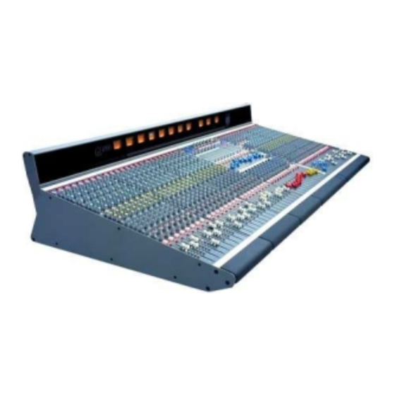
- Page 1 ALLEN&HEATH GL4000 Dual Function Audio Mixing Console USER GUIDE PUBLICATION: AP2642...
-
Page 2: Table Of Contents
UIDE CONTENTS Warranty ............... 2 Introduction ............3 Overview .............. 4 Range and Options ..........5 Dimensions and Weights ........6 Specifications ............7 System Block Diagram ......... 8 Connectors ............10 Earthing .............. 13 Connecting the Power Unit ......... 14 Matching the Signal Levels ......... -
Page 3: Warranty
IMITED ARRANTY This product has been manufactured in the UK by ALLEN & HEATH and is warranted to be free from defects in materials or workmanship for a period of one year from the date of purchase by the original owner. To ensure the high level of performance and reliability for which this equipment has been designed and manufactured please read this User Guide before use. -
Page 4: Introduction
This user guide presents a quick reference to the function and application of the GL4000. For further information on the basic principles of audio system engineering please refer to one of the specialist publications available from bookshops and audio equipment dealers. -
Page 5: Overview
High quality proven reliable parts are used throughout. High performance op-amp and discrete circuits are used to ensure low noise and sonic purity. The GL4000 reflects our commitment to providing the best audio mixing solutions and customer support. -
Page 6: Range And Options
ANGE The following GL4000 models and options are available. For further details please contact your Allen & Heath agent : GL4000-824 - 24 channel console GL4000-832 - 32 channel console GL4000-840 - 40 channel console GL4000-848 - 48 channel console The Stereo models can include mic/stereo line channels dependant on customer specification. -
Page 7: Dimensions And Weights
748 (29.5") 285 (11.2") 57 (126lbs) GL4000M-840 1676 (66") 748 (29.5") 285 (11.2") 67 (148lbs) GL4000M-848 1931 (76") 748 (29.5") 285 (11.2") 77 (170lbs) GL4000-8M 255 (10") 748 (29.5") 285 (11.2") 9 (20lbs) RPS11 483 (19") 232 (9.1") 135 (3U) -
Page 8: Specifications
PECIFICATIONS 0dBu = 0.775 Vrms Reference for high level equipment +4dBu = 1.23 V 0dBV = 1 Vrms Reference for low level equipment -10dBV = 310 mV 0VU meter reading = +4dBu at XLR outputs NPUT Mic/Line Input ....+6dB to +60dB variable Mic/Line + Pad .... - Page 9 WITCHING Protected underpanel mode switches set the console architecture according to the required application, for example FOH or stage monitor. Select these using a pointed object. DIR OUT routes the channel direct out signal through the aux 10 pre/post selector and level control.
-
Page 10: System Block Diagram
SYSTEM DIAGRAM... -
Page 11: Connectors
ONNECTORS Professional gold plated connector types are used to ensure continued reliable operation. All the console main inputs and outputs are balanced XLRs. All 1/4" jacks are 3-pole TRS for operation with balanced or unbalanced equipment. Inserts are provided on all channel inputs, and on Groups, L, R, Mono and all Aux outputs. Aux can be swapped with matrix and LR2 for XLR outputs with inserts IRECT UTPUT... - Page 12 XPANDER PTION Available as a kit to be fitted to the console to expand the busses. Uses 4 25-pin D-type connectors (input and output A and B). Operates at -2dBu line level. Refer to your Allen & Heath agent for further details.
- Page 13 ETERPOD ONNECTOR Recessed 16-pin dual row header for connection to the meterpod. OCAL TEREO ONITOR For connection to a stereo amplifier/speaker system for LR, AFL/ PFL monitoring local to the console. 3-pole 1/4" jack sockets (tip = hot). Impedance matched 50ohm 0dBu nominal line level.
-
Page 14: Earthing
ARTHING The connection to earth (ground) in an audio system is important for two reasons: 1. SAFETY - To protect the operator from high voltage shock associated with the AC mains supply feeding the system, 2. AUDIO PERFORMANCE QUALITY - To minimise the effect of earth (ground) loops which result in audible hum and buzz, and to shield the audio signals from external interference. -
Page 15: Connecting The Power Unit
ONNECTING THE OWER Connect only the Allen & Heath power unit specified for the console. The standard unit for GL4000 is the RPS11. This is an external 3U 19" rack mounted unit that connects to the console via the separate DC cable supplied. The RPS11 is a low noise linear design that converts AC mains voltage to the DC voltages required to power the console. -
Page 16: Matching The Signal Levels
For best results operate the console with the meters averaging around '0' letting the louder passages peak into the 'yellow'. Reduce the gain if the red peak indicators flash. The GL4000 produces a standard XLR output level of +4dBu for a meter reading of 0VU. It is advisable to adjust the power amplifier input gain or fit an attenuator pad if normal console operation results in an output level too high for the connected amplifier. -
Page 17: Mono Input Channel
MONO INPUT +48V - Feeds +48V to pins 2 and 3 of the input XLR for condenser microphones which require phantom power. Plug the microphone in before switching +48V on or off. Use +48V only with balanced microphones and cables. No damage will occur when +48V is switched to balanced non-phantom powered transformer coupled dynamic microphones. - Page 18 AUXILIARY SENDS - Route the channel signal to one or more of 10 auxiliary send busses. These are independent from the main outputs and may be used for effects sends and monitor mixes. The sends are grouped 1-4, 5-8, and 9- 10.
-
Page 19: Stereo Input Channel
STEREO INPUT The stereo channel has two independent input sections: XLR IN for mono microphone or line input, and STEREO LINE IN on jacks for sources such as stereo keyboards, voice modules and effects returns. When using the channel as a mono XLR mic/line input the stereo line input can be independently routed to L-R for a stereo effects return or additional line input. -
Page 20: Stereo Channel Applications
M-S S TEREO ICROPHONES TEREO ICROHONES This example shows two cardiod microphones arranged as an X-Y coincident pair. This minimises phase differences which can cause problems when the mics are arranged as a spaced pair. The mic input stages are patched into a stereo line input for single fader control. -
Page 21: Group Section
GROUP MATRIX MASTER - Controls the output of the matrix mix. Adjust LEV to trim the output level to match the connected equipment. ON switches the output on or off, ideal for checking the effect of individual or combinations of speakers in a multispeaker system. AFL lets you monitor the signal post level trim, post insert, but pre ON switch. -
Page 22: Lr Section
THE CONSOLE MATRIX - The GL4000 includes a versatile 11 x 4 output matrix. This comprises four independent outputs each with level control, ON switch and AFL monitoring. Each matrix mix is created from the desired combination of group (x8), L (left), R (right) and M (mono) signals. - Page 23 THE CONSOLE LR AND LR2 OUTPUTS - In addition to the main L and R outputs the GL4000 includes a secondary pair of outputs called L2 and R2. These follow the LR mix and may be selected either pre or post LR faders. As with...
-
Page 24: Mono And Master Section
MONO 2-TRACK STEREO RETURN - The incoming level can be trimmed from OFF to +10dB gain and routed direct to the LR mix for intermission or recording replay. Monitor the signal post LEV trim and pre REPLAY switch using STEREO PFL which automatically overrides the signal in the headphones and local monitor. - Page 25 THE MONO MIX - The GL4000 includes an independent mix buss for the M (mono) output. Each channel and group can be routed direct to this buss by pressing the related M routing switch. The signal is sourced pre PAN control so that the mono mix is not affected when the stereo mix image is adjusted.
- Page 26 It is recommended that these are the standard 12V 2.5 watt type. THE CONSOLE MONITOR The GL4000 offers a comprehensive signal monitoring system. Apart from the extensive metering facilities there is a monitor section which operates independently of the main outputs.
-
Page 27: The Mute System
YSTEM Each GL4000 input channel, group, aux send and main output (L,R,M) is provided with a mute switch. This turns the audio signal on or off. The GL4000 provides a 'soft' mute system controlled by a built-in microprocessor which gives far greater control and versatility than the conventional systems found in other consoles. - Page 28 WITCH Press MUTE once to mute the channel signal. The red LED will turn on. The audio signal will turn off (channel muted). Mute affects the post-fade signal and will also affect the pre-fade signal if the internal option links are configured to do so (factory default setting).
-
Page 29: Mute Groups
The GL4000 includes 8 mute groups controlled by a bank of large buttons to the right of the master faders. These may be selected one at a time or together depending on the mode of operation preferred. - Page 30 ROGRAM ROUP Press EDIT GROUP The red LED will start flashing. This puts the mute system into 'edit mode'. The mute groups are programmed or edited 'off-line'. This lets you change groups during a live show without affecting the mute status of the channels. Press the MUTE GROUP to be programmed.
- Page 31 UTES FF OR N IN A ROUP It is often useful to turn off (clear) or turn on (set) all the console mutes within a mute group. This is done in 'edit mode' so that the console mutes are not affected while the group is being edited. FF OR N ALL UTES IN A...
-
Page 32: Mute Safes
You may also prefer to take manual control of lead performers to prevent their channels being accidentally affected by the mute automation or MIDI. The GL4000 includes a 'mute safes' facility so that selected channels can be 'made safe' from the mute groups, patches and MIDI control. These settings are programmed into non-volatile memory so that its contents are retained when power is removed. -
Page 33: Mute Patches
MIDI for sophisticated show control. Patches can be archived and recalled via MIDI. The GL4000 includes 128 mute patch memories. The patch number is simply dialled up on the 3 segment display and its contents recalled or overwritten with the current console settings. -
Page 34: The Patch Display
ATCH ISPLAY ORMAL Shows selected patch number Indicates which patch which will overwrite the console mutes when you press RECALL, or be overwritten when you press STORE. The ACTIVE PATCH dot tells you how the displayed number relates to the current console mute settings: ACTIVE PATCH on : Displayed patch is the last patch recalled. - Page 35 CROLL HROUGH THE ATCH UMBERS The 128 patches are numbered 0 to 127 . Before 0 there is a special patch called ALL . This is described later. ∧ ∧ ∧ ∧ ∧ ∨ ∨ ∨ ∨ ∨ Press to increment or decrement to the required patch number.
- Page 36 ALL P ATCH Between patch is a special patch function called This lets you overwrite all 128 patches with the current console mute settings. You would normally do this before programming the patches for a particular show. Typical use would be : Turn all mutes off in all patches (clear), then edit the mutes on for required channels.
-
Page 37: Quicksolo
QuickSolo is most useful during sound checking where you can listen to the contribution of individual signals to the mix. The GL4000 QuickSolo system lets you quickly solo selected channels using a two key press that prevents accidental operation during a live performance. You can toggle between your last selected solo setting and the full mix to compare the effect. -
Page 38: Solo Safes
The GL4000 includes a 'solo safe' facility so that selected mutes can be disabled from the solo system. This works in the same way as the 'mute safes' described earlier but affects solo and not the mute groups or patches. -
Page 39: Midi
Sophisticated recording and live sound control is now possible by interfacing sound consoles with other MIDI equipment. The GL4000 includes a full opto-isolated Musical Instrument Digital Interface(MIDI) system. Standard 5-pin IN, OUT, THRU sockets allow connection to external MIDI equipment including computer show control systems, sequencers, data archiving systems, musical instruments and so on. - Page 40 MIDI C ELECT THE ONSOLE HANNEL Press and hold SHIFT + PREVIEW PATCH together to enter 'MIDI mode'. The display MIDI dot turns on and the current MIDI channel number is shown. While holding SHIFT + PREVIEW scroll through the MIDI ∧...
- Page 41 HANNEL UTES Pressing any console mute switch transmits a MIDI Note On message unless MIDI has been disabled. Similarly receiving the correct Note On message will control the channel mute unless it has been made 'mute safe' or MIDI disabled. Console mutes are mapped to MIDI Note numbers as shown.
- Page 42 This is ideal when you want to archive settings and recall them at a later date, for example a re-run of a previous performance. You can also use the dump facility to program additional GL4000 consoles, for example when setting up duplicate shows or swapping consoles around. MIDI D...
-
Page 43: Technical Support
ECHNICAL UPPORT Should you have any queries about the GL4000 console automation system please quote the console model, serial number and software version number in any communication with Allen & Heath or appointed service agent. The system has been designed and tested to be reliable under the harsh conditions typical of live sound 'on the road'. - Page 44 ESET Should the console memory become corrupted it can be reset to the factory defaults by performing a hard reset : Hold down EDIT GROUP + PREVIEW GROUP while powering up the console. The following condition set : All console mutes turned on. Patch display shows All mute patches cleared (mutes turned off).
-
Page 45: Front-Of House Application
RONT OUSE WITH RECORDING... - Page 46 (around 1millisecond per foot). It is also important to EQ the sound to prevent distraction, usually by removing some LF and HF. In some cases you may wish to send a different mix from LR to the fill speakers. The GL4000 offers two ways of controlling fills : 1.
- Page 47 ONITORS Otherwise known as foldback or cue sends, the monitor mixes are created from the console aux sends. These feed amplifier/speaker systems positioned on-stage for the performers, backstage for the stage crew, in the pit for the orchestra, and so on. The channel aux sends are usually set PRE (pre-fade) for monitors so that they are independent of the front-of-house mix levels.
- Page 48 A simultaneous stereo recording can be made of the performance by feeding additional console outputs to a 2-track such as a cassette or DAT recorder. The GL4000 offers several methods depending on the application. In each case a separate output level trim is provided so that you can match the console to the operating level of the recorder, usually +4dBu (high level) or -10dBV (low level).
-
Page 49: On-Stage Monitor Application
TAGE ONITOR Mixing system for on-stage control of performers monitor loudspeakers (wedges). Provides 12 monitors (10 wedges + LR sidefills) and a dedicated engineers 'listen' wedge output. - Page 50 USING THE GL4000 AS A MONITOR CONSOLE The GL4000 can be easily configured to function as a dedicated 12 buss on-stage monitor console. Here, the console is positioned at the side of the stage giving the monitor engineer a clear view of the performers on stage. The sound sources are split to feed both the front-of-house console which controls the PA mix, and the monitor console which controls only the mix to the musicians own monitor speakers.
- Page 51 ONITOR ONSOLE The GL4000 provides the unique facility to record the show from the monitor console rather than additional dedicated recording console. This significantly adds to the value of the service offered to the performers in situations where the front-of-house engineer is overworked or budget and time are tight.
-
Page 52: Multi-Speaker System Application
ULTI PEAKER YSTEM 6 Speaker system driven from the matrix and LR2 outputs. Provides output balance and level trim independent of the mix levels. All outputs are balanced XLR with inserts for EQ, delay or other signal processors. UTPUT EVEL ATCHING AND ALANCE This example shows the matrix and LR2 outputs feeding the speaker system. -
Page 53: Internal Link Options
INTERNAL LINK OPTIONS The GL4000 is configured to satisfy most applications that should be encountered. However, the following internal link options are offered for those applications that may require alternative settings. These options require access to the internal circuit assemblies and resoldering of circuit board links.
Need help?
Do you have a question about the GL4000 and is the answer not in the manual?
Questions and answers