Motorola MC67 User Manual
Mobile computer
Hide thumbs
Also See for MC67:
- Integrator manual (164 pages) ,
- User manual (146 pages) ,
- Quick start manual (2 pages)
Table of Contents
Advertisement
Advertisement
Table of Contents
Troubleshooting

Related Manuals for Motorola MC67


Summary of Contents for Motorola MC67
- Page 1 MC67 USER GUIDE...
- Page 3 MC67 USER GUIDE 72E-161697-02 Rev. A August 2013...
- Page 4 Motorola. No right to copy a licensed program in whole or in part is granted, except as permitted under copyright law. The user shall not modify, merge, or incorporate any form or portion of a licensed program with other program material, create a derivative work from a licensed program, or use a licensed program in a network without written permission from Motorola.
-
Page 5: Revision History
Revision History Changes to the original guide are listed below: Change Date Description -01 Rev. A 09/19/12 Initial release. -02 Rev. A 08/30/13 Add CDMA WAN support. - Page 6 MC67 User Guide...
-
Page 7: Table Of Contents
Charging the Battery ........................ 1-5 Charging the Main Battery ....................1-5 Charging Spare Batteries ....................1-6 Charging Temperature ....................... 1-6 Powering On the MC67 ......................1-6 Calibrating the Screen ......................1-6 Checking Battery Status ........................ 1-6 Replacing the Battery ........................1-7 Replacing the microSD Card ...................... - Page 8 MC67 User Guide Turning Off the Radios ......................1-10 Chapter 2: Using the MC67 Introduction ............................ 2-1 Features ............................2-1 LED Indicators ..........................2-2 Keypads ............................2-3 Finger Scrolling ..........................2-4 Home Screen ..........................2-4 Classic Today Screen ......................2-6 Status Bar ..........................
- Page 9 Table of Contents Video Configuration ......................... 3-8 Viewing Pictures and Videos ......................3-9 Customizing Pictures & Videos ...................... 3-9 Chapter 4: Making Calls Introduction ............................ 4-1 Making a Call ..........................4-1 Using the Phone Keypad ......................4-1 Smart Dialing ........................... 4-2 Using Contacts .........................
- Page 10 MC67 User Guide Text Messaging ..........................6-2 Viewing Text Messages ......................6-2 Sending a Text Message ......................6-4 Using a Dual Line SIM ........................6-5 Chapter 7: Bluetooth Introduction ............................ 7-1 Adaptive Frequency Hopping ......................7-1 Security ............................7-2 Security Mode 3 (Link Level Encryption) .................
- Page 11 Miscellaneous ........................7-39 Chapter 8: Using GPS Navigation Introduction ............................ 8-1 Software Installation ........................8-1 MC67 GPS Setup .......................... 8-1 Operation ............................8-2 GPS Maps on microSD Cards ....................8-2 Answering a Phone Call While Using GPS ................8-2 Losing the GPS Signal While in a Vehicle ................8-2 Assisted GPS ..........................
- Page 12 Battery Charging and Operating Power ................... 10-13 LED Charge Indications ......................10-14 Charging Temperature ....................... 10-14 Trigger Handle ..........................10-15 Inserting the MC67 into the Trigger Handle ................10-15 Removing the MC67 ........................ 10-15 Scanning ..........................10-15 Chapter 11: Maintenance & Troubleshooting Introduction ............................
- Page 13 Connector ........................... 11-4 Cleaning Cradle Connectors ....................11-4 Cleaning Frequency ......................... 11-5 Troubleshooting ..........................11-5 MC67 ............................11-5 Single Slot USB Cradle ......................11-8 Four Slot Ethernet Cradle ......................11-9 Vehicle Cradle .......................... 11-9 Four Slot Battery Charger ......................11-10 Cables ............................
- Page 14 MC67 User Guide...
-
Page 15: About This Guide
NOTE Screens and windows pictured in this guide are samples and can differ from actual screens. Documentation Set The documentation set for the MC67 provides information for specific user needs, and includes: • MC67 Quick Start Guide - describes how to get the MC67 up and running. -
Page 16: Configurations
MC67 User Guide Configurations This guide covers the following configurations: Data Operating Configuration Radios Display Memory Capture Keypads System Options MC67NA WLAN: 802.11 3.5” VGA 512 MB RAM/ 2D imager or Windows Numeric, a/b/g/n Color 2 GB Flash 2D imager... -
Page 17: Chapter Descriptions
Topics covered in this guide are as follows: • Chapter 1, Getting Started provides information on getting the MC67 up and running for the first time. • Chapter 2, Using the MC67 provides basic instructions for using the MC67, including powering on and resetting the MC67. -
Page 18: Related Documents
• Model number or product name (found on manufacturing label) • Software type and version number • IMEI number. Manufacturing label Motorola Solutions responds to calls by email, telephone or fax within the time limits set forth in support agreements. - Page 19 About This Guide xvii If the problem cannot be solved by Motorola Solutions Global Customer Support, the user may need to return the equipment for servicing and will be given specific directions. Motorola Solutions is not responsible for any damages incurred during shipment if the approved shipping container is not used. Shipping the units improperly can possibly void the warranty.
- Page 20 MC67 User Guide...
-
Page 21: Introduction
CHAPTER 1 GETTING STARTED Introduction This chapter lists the parts and accessories for the MC67 and explains how to set up the MC67 for the first time. Unpacking Carefully remove all protective material from the MC67 and save the shipping container for later storage and shipping. -
Page 22: Installing A Microsd Card
1 - 2 MC67 User Guide Getting Started To start using the MC67 for the first time: Install a micro secure digital (SD) card (optional) Install the subscriber identification module (SIM) card (GSM/UMTS only) Install the battery. Charge the MC67. -
Page 23: Installing The Sim Card
NOTE GSM/UMTS networks only. Global System for Mobile communications (GSM) phone service requires a SIM card. Obtain the card from a service provider. The card fits into the MC67 and can contain the following information: • Mobile phone service provider account details. -
Page 24: Installing The Battery
Installing the Battery To install the battery. Insert the battery, bottom first, into the battery compartment in the back of the MC67. Press the battery down into the battery compartment until the battery release latch snaps (two clicks) into place. -
Page 25: Charging The Battery
Battery Safety Guidelines on page 11-2. Charging the Main Battery Before using the MC67 for the first time, charge the main battery until the amber Charging/Battery Status light emitting diode (LED) remains lit (see Table 1-1 on page 1-6 for charge status indications). To charge the MC67, use a cable or a cradle with the appropriate power supply. -
Page 26: Charging Spare Batteries
If during installation of the battery, the battery has significant charge the MC67 turns on. NOTE Press the Power button to turn on the MC67. The splash screen displays for about a minute as the MC67 initializes its flash file system, then the calibration window appears. -
Page 27: Calibrating The Screen
Replacing the Battery CAUTION The MC67 backup battery retains data for up to 15 minutes. Replace the battery within 15 minutes to ensure that application states are maintained and that data is not lost. If the MC67 is in a cradle, remove it before performing a Safe Battery Swap. -
Page 28: Replacing The Microsd Card
Replacing the microSD Card CAUTION The MC67 backup battery retains data for up to 15 minutes. Replace the battery within 15 minutes to ensure that application states are maintained and that data is not lost. To replace an microSD card: If the MC67 is in a cradle, remove it before performing a Safe Battery Swap. -
Page 29: Battery Management
If the MC67 is in a cradle, remove it before performing a Safe Battery Swap. If the MC67 is in suspend mode, press the red Power button to wake the device. Press the red Power button. The Power Action Key window appears. -
Page 30: Changing The Backlight Settings
Tap the Disable keylight check box to turn off the keypad backlight. Select OK. Turning Off the Radios The MC67 includes Wireless Manager, which provides a simple method of enabling, disabling, and configuring all the MC67’s wireless capabilities. To open Wireless Manager, tap >... - Page 31 Tap Activation. The CDMA Activation window appears. Tap Start Activation and PRL Update. Follow the on-screen instructions. For detailed information for configuring the phone and activating on a different network, refer to the MC67 Integrator Guide. Switching from CDMA to GSM/UMTS To switch from a CDMA network to a GSM/UTMAS network: Tap Start >...
- Page 32 1 - 12 MC67 User Guide The window closes. Tap Network Setup & Activation. NOTE Switching radio bands may not be available on all networks. In the GSM/UMTS Settings drop-down list, select connection type. Options: Auto (GSM&UTMS) GSM Only UMTS Only.
-
Page 33: Chapter 2 Using The Mc67
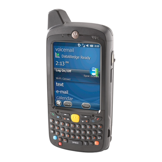
CHAPTER 2 USING THE MC67 Introduction This chapter explains the buttons, status icons, and controls on the MC67, and provides basic instructions for using the MC67, including resetting the MC67 and entering data. Features WAN Radio Charging/Battery Data Capture Touch Screen with... -
Page 34: Led Indicators
Figure 2-2 LED Indicators The MC67 has three light emitting diode (LED) indicators. The Data Capture LED indicates status for scanning. The Charging/Battery Status LED indicates battery charging and status.The Radio Status LED indicates Wide Area Network (WAN) radio status. -
Page 35: Keypads
Chapter 4, Making Calls, or refer to the MC67 Integrator Guide. Keypads The MC67 offers six keypad configurations: Numeric, QWERTY, AZERTY, QWERTZ, Direct Store Delivery (DSD) and Personal Information Manager (PIM). MC67 Numeric Keypad Figure 2-4... -
Page 36: Finger Scrolling
To auto-scroll, flick a finger upward or downward on the screen. Touch the screen to stop scrolling. Home Screen The default home screen on the MC67 is the Windows Embedded Handheld Home screen. The Home screen contains a Status Bar at the top of the screen and a Tile Bar at the bottom of the screen. - Page 37 Using the MC67 2 - 5 Moving Today Screen Figure 2-6 Also touch and hold the Information Status bar and move it up and down over an application name. Remove finger and the Information Status bar and application name center in the screen.
-
Page 38: Classic Today Screen
2 - 6 MC67 User Guide Classic Today Screen The user can change to the classic Today screen layout that is used in Windows Mobile 6.1. Status Bar Today Screen Task Tray Tile Bar Classic Today Screen Figure 2-9 To change to the classic view tap >... -
Page 39: Status Bar
Using the MC67 2 - 7 Task Tray Icons Table 2-2 Icon Name Description Wireless connection Wireless connection status icon. Indicates wireless local area network status (WLAN) signal strength and opens the Wireless Applications menu. Bluetooth Enabled icon appears in the task tray and indicates that the... - Page 40 2 - 8 MC67 User Guide Status Bar Icons (Continued) Table 2-3 Icon Description Icon Description Connectivity Connection is active. Connection is not active. Synchronization is occurring. wireless fidelity (Wi-Fi) available. Wi-Fi in use. HSPA+ available. 3G available. GPRS available.
- Page 41 Low Backup Battery Indicates that the backup battery is low. Notifications Indicates that notifications are available. Headset Indicates that a wireless stereo headset is connected to the MC67. Connectivity Displays the Connectivity dialog box. Phone Data Displays the Phone dialog box.
-
Page 42: Tile Bar
2 - 10 MC67 User Guide Tile Bar The Tile Bar, located at the bottom of the screen, contains the Start tile to open the Start Menu. It also displays tiles that vary depending upon the open application. Tile Bar Examples... - Page 43 Rapid Deployment Client - Allows the RTlogEvent - Use when instructed by MC67 user to stage a device for initial use by Motorola Solutions support personnel. initiating the deployment of settings, firmware, and software. Requires the purchase of an Mobility Services Platform (MSP) client license per device.
-
Page 44: Adjusting Volume
A cold boot also restarts the MC67, and also initializes some drivers. Data saved in flash memory or a memory card is not lost. If the MC67 is not functioning properly, perform a warm boot first. If the MC67 still does not respond, perform a cold boot. -
Page 45: Un-Locking With Simple Pin
Using the MC67 2 - 13 Unlock Device Window Figure 2-14 If the MC67 was locked with a PIN or password, a prompt appears. Un-locking with Simple PIN When the MC67 is locked, the Lock screen appears. Simple PIN Lock Screen Figure 2-15 Enter the password to un-lock the device. -
Page 46: Battery Status Indications
2 - 14 MC67 User Guide Strong Password Lock Screen Figure 2-16 Enter the strong password and then tap Unlock. NOTE If the user enters an incorrect password eight times, the user is requested to enter a code before trying again. -
Page 47: Battery Reserve Options
Figure 2-18 Battery Reserve Options If the charge of the battery reaches a critical threshold, the MC67 shuts down. This threshold can be changed but affects the amount of time that data can be retained. > Settings > System > Power > RunTime. A warning message appears. -
Page 48: Main Battery Temperature Notifications
MC67. • Level 3: Temperature Error; this level indicates the battery has reached an unusable temperature threshold and immediately suspends the MC67. This level does not have any graphical notification associated with it. Main Battery Temperature Watch Dialog Box... -
Page 49: Interactive Sensor Technology
It can also be used to keep the MC67 active while it is in movement to prevent it from quickly going into suspend mode while in use. -
Page 50: Stylus
IST features a log for recording the free fall events. This log records the date, time and the time period of the free fall. Stylus Use the MC67 stylus to select items and enter information. The stylus functions as a mouse. • Tap: Touch the screen once with the stylus to press option buttons and open menu items. -
Page 51: Using Voice-Over-Ip
GHz band avoids some noise sources that may occur on the 802.11b/g (2.4 GHz) band due to wireless interference. When using a Bluetooth headset with the MC67 and VoWLAN, it is required to use the Bluetooth Headset profile instead of Hands-free profile. Use the buttons on the MC67 to answer and end calls. See... - Page 52 2 - 20 MC67 User Guide...
-
Page 53: Chapter 3 Data Capture
NOTE To enable Pick List Mode, configure in DataWedge or set in an application using a API command. • Pick List Mode: This mode allows the user to selectively decode a bar code when more than one bar code is in the MC67’s field of view. To accomplish this, move the aiming crosshair or dot over the... -
Page 54: Digital Camera
(either 1D or 2D). • Image Capture Mode: Use this mode to capture an image within the MC67’s field of view. This is useful for capturing signatures or images of items like damaged boxes. - Page 55 The Scan/Decode LED lights red to indicate that scanning is in process, then lights green and a beep sounds, by default, to indicate the bar code was decoded successfully. Note that when the MC67 is in Pick List Mode, the imager does not decode the bar code until the crosshair or aiming dot touches the bar code.
-
Page 56: Digital Camera Scanning
MC67 User Guide Digital Camera Scanning To read a bar code, a scan-enabled application is required. The MC67 contains the DataWedge application that allows the user to enable the camera, decode the bar code data and display the bar code content. -
Page 57: Disable Datawedge
The Camera window displays the view finder. Information about the current settings or the remaining number of pictures that can be saved to the MC67 are displayed on the lower right corner of the screen. Check the image on the view finder, adjust if necessary. -
Page 58: Timer Mode
Tap inside the area to crop the picture, or outside of the area to cancel cropping. Setting a Picture as Wallpaper To add a custom look to the Home screen of the MC67 (using the Windows Home screen); apply a wallpaper using any image. To set an image as a Home wallpaper: Tap and hold a thumbnail, then select Set as Home Background. -
Page 59: Recording A Video
Data Capture 3 - 7 > Pictures & Videos. Tap Menu, then configure the device settings. • Video - Tap to switch to video mode. • Mode - Select from the following modes to take the picture: Normal - Takes picture using the default settings. •... -
Page 60: Video Configuration
3 - 8 MC67 User Guide Press the Enter key to stop recording. Video Configuration To configure the video settings: Launch the Video application. Tap Menu, then configure the device settings. • Still - Tap to switch to still (camera) mode. - Page 61 Data Capture 3 - 9 On the General tab, set the following options: • Select the size of the pictures to send through e-mail. Only pictures sent through an e-mail message is resized, the original picture remains unchanged. • Resize pictures for faster e-mail transfer. •...
- Page 62 3 - 10 MC67 User Guide...
-
Page 63: Chapter 4 Making Calls
CHAPTER 4 MAKING CALLS Introduction Use the MC67 to make phone calls, keep track of calls, and send text messages. Wireless service providers may also provide other services such as voice mail, call forwarding, and caller ID. Also use the phone to connect to an Internet Service Provider (ISP) or work network in order to browse the Web and read e-mail over Evolved High-Speed Packet Access (HSPA+) or CDMA Evolution Data Optimized (EvDO) using cellular line. -
Page 64: Smart Dialing
4 - 2 MC67 User Guide Smart Dialing Smart Dialing makes it easy to dial a phone number. When the user starts entering numbers or characters, Smart Dialing automatically searches and sorts the contact entries on the SIM card, in Contacts, and the phone numbers in Call History (including incoming, outgoing, and missed calls). -
Page 65: Using Contacts
Making Calls 4 - 3 Using Contacts Use Contacts to make a call without looking up or entering the phone number. To make a call from Contacts: Tap Contacts. From the contact list, tap and hold the contact name. Contacts Menu Figure 4-2 Tap Call Work, Call Home or Call Mobile. -
Page 66: Making A Speed Dial Call
To stop dialing or end the call, press Answering a Call A dialog box appears on the MC67 when it receives an incoming call. If the phone is set to ring, a ring tone sounds. Answer or ignore the incoming call. -
Page 67: Incoming Call Features
SIM card is not inserted or the phone is not activated. The service provider can program additional emergency numbers into the SIM card. However, the SIM card must be inserted in the MC67 in order to use the numbers stored on it. See the service provider for additional information. -
Page 68: Adjusting Audio Volume
4 - 6 MC67 User Guide appropriately before putting the headset on. When a Bluetooth headset is connected the speakerphone is muted. Adjusting Audio Volume Use the Volume buttons to adjust the volume of the ringer when not in a call and the audio volume when in a call. -
Page 69: Using Call History
Making Calls 4 - 7 Using Call History Use Call History to call someone who was recently called, or recently called in. Call History provides the time and duration of all incoming, outgoing, and missed calls. It also provides a summary of total calls and easy access to notes taken during a call. -
Page 70: Deleting All Call History Items
4 - 8 MC67 User Guide Call History - Call Timers Figure 4-7 Tap Reset. (The All Calls: counter cannot be reset.) Tap OK to exit the Call Timers window. Deleting All Call History Items Press to display the Phone dialer. -
Page 71: Using The Call History Menu
Making Calls 4 - 9 NOTE When more than one call is on the phone line, only the duration of the first call is recorded. Tap OK and then OK to exit. Using the Call History Menu Use the Call History menu to dial voice mail, save to contacts, view a note, delete a listing, send an SMS and make a call. -
Page 72: Swapping Calls
4 - 10 MC67 User Guide After the call is answered, tap Conference to place the calls in conference mode. Tap Hold to place the conference on hold. Enter another phone number and tap Talk. After the call is answered, tap Conference to place all the calls in conference mode. - Page 73 Call Conferencing - Conferencing Figure 4-11 Tap Swap to move from one call to the other. Tap End or press the red phone key on the MC67 keypad to end each call. Swapping Calls (CDMA) For use with CDMA networks only.
-
Page 74: Speed Dial Setup
4 - 12 MC67 User Guide Answer a Call Figure 4-12 When a second call arrives, tap Answer (icon). The first call is placed on hold. Tap Talk to swap from one call to the other. Call Swapping Figure 4-13 Tap End or press the red phone key on the keypad to end the active call. - Page 75 Making Calls 4 - 13 Contacts Figure 4-14 Tap the desired contact name and number in the list. Speed Dial Contact Location Figure 4-15 In the Location field, tap the up/down arrows to select an available location to assign as the new speed dial entry.
-
Page 76: Editing A Speed Dial Entry
4 - 14 MC67 User Guide > Contacts. Contacts Figure 4-17 Tap a contact name. Tap Menu > Add to Speed Dial. Speed Dial Contact Location Figure 4-18 Tap the up/down arrows to select an available location to assign as the new speed dial entry. The first speed dial location is reserved for voice mail. -
Page 77: Deleting A Speed Dial Entry
Making Calls 4 - 15 Speed Dial Contact List Figure 4-19 Tap and hold the contact name. Tap Edit..Change the name, phone number, or location information. Tap OK. Speed Dial Contacts NOTE Editing names and phone numbers in does not alter contact information in >... - Page 78 4 - 16 MC67 User Guide...
-
Page 79: Chapter 5 Using Wlan
Wireless Local Area Networks (WLANs) allow the MC67 to communicate wirelessly inside a building. Before using the MC67 on a WLAN, the facility must be set up with the required hardware to run the WLAN (sometimes known as infrastructure). The infrastructure and the MC67 must both be properly configured to enable this communication. -
Page 80: Connecting To The Internet
5 - 2 MC67 User Guide Wireless Launch Window Figure 5-1 Refer to the Wireless Fusion Enterprise Mobility Suite User Guide for Version X2.xx for detailed information on using and configuring Fusion Wireless Companion. To access the on-device Fusion Help tap >... -
Page 81: Fusion Setup
Using WLAN 5 - 3 Supported Applications (Continued) Table 5-1 Application Description Options Invokes the Options application which allows the user to configure the Fusion option settings. Wireless Status Invokes the Wireless Status application which allows the user to view the status of the current wireless connection. - Page 82 5 - 4 MC67 User Guide Operating Mode Dialog Box Figure 5-3 Tap Next. The Security Mode dialog box displays. In the Security Mode drop-down list, select Legacy (Pre-WPA). Security/Authentication Dialog Box Figure 5-4 In the Authentication drop-down list, select None.
- Page 83 Using WLAN 5 - 5 WEP-40 WEP Keys Dialog Box Figure 5-6 In the Edit Key drop-down list, select the key to enter. In the Key field, enter 10 hexadecimal characters. In the Confirm field, re-enter the key. When the keys match, a message appears indicating that the keys match.
- Page 84 5 - 6 MC67 User Guide...
-
Page 85: Chapter 6 Messaging
CHAPTER 6 MESSAGING Introduction This chapter describes how to use Email and text messaging. Email Use email to send messages to other users. See Email Setup on page 6-6 for information on setting up an Email account. Creating an Email Message To create an email message: Press >... -
Page 86: Replying To A Message
160 characters. Short text messages delivered over mobile networks transmit from the sending MC67, are stored in a central short message center, then forwarded to the destination mobile device. If the recipient is not available, the message is stored and can be sent later. - Page 87 Messaging 6 - 3 New Text Message Options Figure 6-2 When the phone function is off, the user can still view received text message: > Text or on the Today screen, tap the text message on the Information Bar. Tap to View Text Messages. Text Messaging on Today Screen Figure 6-3 The Text Messages window appears.
-
Page 88: Sending A Text Message
6 - 4 MC67 User Guide NOTE If the phone is turned off and the user tried to call the sender, send a reply, or forward the message, the user is prompted to turn the phone function on. Sending a Text Message To create a text message: On the Phone screen, select a contact name to send a message to. -
Page 89: Using A Dual Line Sim
Messaging 6 - 5 If the user is out of coverage area, the message is saved in the Drafts folder. The user has to manually re-send it when the user returns to a coverage area. NOTE Using a Dual Line SIM NOTE Check with the service provider for availability. - Page 90 The MC67’s Messaging application lets users access and manage multiple email accounts simultaneously in one convenient location. To send and receive email messages through an ISP (Internet Service Provider) account, or to use the MC67 to access corporate email through a VPN (Virtual Private Network), first set up an IMAP or POP account.
- Page 91 6 - 7 Tap Next. Tap the Automatic Send/Receive: field and select the time interval for the MC67 to send and check for new email messages. Tap the Review all download settings link for additional download settings and options. See...
- Page 92 Tap Done once completed making updates to these settings. Tap Next. In the Automatic Send/Receive: drop-down list select the time interval for the MC67 to send and check for new email. Tap the Review all download settings link for additional download settings and options.
- Page 93 (open: no firewall), Work (behind a firewall) or a data connection. Tap Done and then tap Next. In the Automatic Send/Receive drop-down list, select the time interval the MC67 sends and checks for new email. In the Download messages drop-down list, select the age range of messages to download from the server to the MC67.
- Page 94 6 - 10 MC67 User Guide...
-
Page 95: Chapter 7 Bluetooth
MC67 as a modem, create a dial-up modem connection between a computer and MC67. The MC67 with Bluetooth technology uses either the StoneStreet Bluetooth stack or the Microsoft Bluetooth stack. To write an application that uses the StoneStreet One Bluetooth stack APIs, refer to the Enterprise Mobility Developer Kit (EMDK) Help. -
Page 96: Security
MC67 User Guide The Bluetooth radio in this MC67 operates as a Class 2 device power class. The maximum output power is 2.5mW and the expected range is 10 meters (32 feet). A definition of ranges based on power class is difficult to obtain due to power and device differences, and whether one measures open space or closed office space. -
Page 97: Fips 140-2
Serial Port Profile. Bluetooth Configuration By default, the MC67 is configured to using the Microsoft Bluetooth stack. Refer to the MC67 Integrator Guide, Appendix B, for information on switching to the StoneStreet One Bluetooth stack. -
Page 98: Bluetooth Power States
If there is an active Bluetooth connection between the MC67 and another Bluetooth device and there is no data activity, the MC67 will timeout. However, if the user presses the Power button on the MC67, the MC67 will suspend and upon receiving data from a remote Bluetooth device, the MC67 will wake from suspend mode. - Page 99 By default the MC67 has a FIPS key installed. If required, the user can generate a new FIPS NOTE key. If a new key is generated on the MC67, the same key is required to be used on the other Bluetooth device. The user must transfer the key to the other device.
-
Page 100: Using Microsoft Bluetooth Stack
Perform a warm boot. Device Status Use the Device Status option to set if the MC67 would be seem by other Bluetooth devices. Touch the Device Status option to toggle the MC67 from Hidden to Discoverable. Using Microsoft Bluetooth Stack The following sections provide information on using the Microsoft Bluetooth stack. -
Page 101: Enabling Bluetooth
Bluetooth 7 - 7 exchange information with other Bluetooth devices (within range). Communicate only with Bluetooth radios in close proximity. NOTE To achieve the best battery life turn off radios not in use. Enabling Bluetooth There are three ways to enable Bluetooth: Microsoft Bluetooth application: >... -
Page 102: Discovering Bluetooth Device(S)
Tap the Bluetooth On tab to turn the Bluetooth radio off. Tap X. Discovering Bluetooth Device(s) The MC67 can receive information from discovered devices without pairing. However, once paired, the MC67 and a paired device exchange information automatically when the Bluetooth radio is turned on. See Pairing with Discovered Device(s) on page 7-32 for more information. - Page 103 Bluetooth 7 - 9 Searching for Bluetooth Devices Figure 7-4 Select a device from the list. Select a Bluetooth Device Figure 7-5 Tap Next. The Enter Passcode window appears. NOTE If Smart-pairing is configured and the device is requesting one of the pre-defined PINs, the Enter Passcode window does not appear.
-
Page 104: Available Services
If the device has a specific passcode, enter it in the Passcode field and tap Next. If the device does not have a specific passcode, enter one in the Passcode field and tap Next. The MC67 tries to connect with the other device. - Page 105 Select Beam File. The MC67 searches for Bluetooth devices in the area. Tap Tap to send next to the Bluetooth device to send the file to. The MC67 communicates with the device and sends the file. When completed, Tap to send changes to Done.
-
Page 106: Internet Sharing
When completed, Tap to send changes to Done. Internet Sharing Internet Sharing allows the user to connect a computer or laptop to the MC67 and use the MC67 as a modem to connect to an office network or Internet Service Provider (ISP). -
Page 107: Serial Port Services
Ensure that the two devices are within 30 feet (10 meters) of one another. > Settings > Connections > Bluetooth > Devices. Tap Add new device. The MC67 begins searching for discoverable Bluetooth devices in the area. Select a device from the list. -
Page 108: Phone Book Access Profile Services
> ActiveSync > Menu > Disconnect. Tap Disconnect. Phone Book Access Profile Services Phone Book Access profile (PBAP) is used to synchronize contacts between a remote device and the MC67. To establish an PBAP synchronization: Ensure that Bluetooth is enabled and discoverable on both devices. - Page 109 Bluetooth 7 - 15 > Settings > Connection > Bluetooth > Devices. Tap Add New Device.The MC67 searches for a Bluetooth device, such as a Car Kit. Select a device from the list. Tap Next. The Enter Passcode window appears.
-
Page 110: Using Bluetooth Stonestreet One Bluetooth Stack
Turn off the Bluetooth radio to save power or if entering an area with radio restrictions (e.g., an airplane). When the radio is off, other Bluetooth devices cannot see or connect to the MC67. Turn on the Bluetooth radio to exchange information with other Bluetooth devices (within range). -
Page 111: Discovering Bluetooth Device(S)
Discovering Bluetooth Device(s) The MC67 can receive information from discovered devices without bonding. However, once bonded, the MC67 and a bonded device exchange information automatically when the Bluetooth radio is turned on. See Pairing with Discovered Device(s) on page 7-32 for more information. - Page 112 7 - 18 MC67 User Guide BTExplorer Window Figure 7-12 Select Explore Services on Remote Device or another from the drop-down list and tap Next. NOTE If a device discovery action has not been previously performed, a device discovery is automatically initiated.
- Page 113 Bluetooth 7 - 19 Select Remote Device Window Figure 7-14 Select a device from the list and tap Next. The MC67 searches for services on the selected Bluetooth device. Device Services Figure 7-15 NOTE If the MC67 discovers a service but the service is not supported, the service icon is grayed-out.
-
Page 114: Available Services
File Transfer Services NOTE Shared folders are a security risk. To transfer files between the MC67 and another Bluetooth enabled device: Ensure that OBEX File Transfer profile is enabled on the MC67. See Profiles on page 7-41 for more information. - Page 115 • Delete - delete the selected file on the remote device. • Get File - copy the file from the remote device to the MC67. • Put File - copy a file from the MC67 to the remote device. Creating a New File or Folder To create a new folder or file on the remote device: Tap and hold on the screen and select New >...
-
Page 116: Connecting To The Internet Using An Access Point
NOTE Network Access profile is not supported. Dial-Up Networking Services Dial-up networking allows the user to connect the MC67 to a Bluetooth Phone and use the Bluetooth Phone as a modem to connect to an office network or ISP. Before setting up dial-up networking, obtain dial-up information and other necessary settings (username, password and domain name, if required) for the office network or ISP. - Page 117 BTExplorer searches for Bluetooth devices in the area. The discovered devices display in the Select Remote Device window. Select the Bluetooth Phone from the list and tap Next. The MC67 searches for services on the Bluetooth Phone. Select Remote Service Window Figure 7-20 Select Dial-up Networking Gateway service from the list and tap Next.
-
Page 118: Add A Dial-Up Entry
Select Dial-up Networking Entry Window Figure 7-22 Select the entry and tap OK. The MC67 begins to communicate with the Bluetooth phone. If required, the phone requests permission to communicate with the MC67. Confirm the connection on the phone. The Network Log On window appears. -
Page 119: Object Exchange Push Services
To exchange contact information with another Bluetooth enabled device: Ensure the MC67 is discoverable and connectable. See Device Info on page 7-34. Ensure that the OBEX Object Push profile is enabled on the MC67. See Profiles on page 7-41 for more information. - Page 120 7 - 26 MC67 User Guide NOTE Prior to sending and receiving contacts, a default contact must be set up before attempting to send a contact. Tap and hold on OBEX Object Push and select Connect. OBEX Object Push Window Figure 7-25 In the Action: drop-down list, select Send Contact Information.
- Page 121 NOTE Prior to sending and receiving contacts, a default contact must be set up before attempting to send a contact. Ensure that the MC67 is connectable. Tap and hold on OBEX Object Push and select Connect. The OBEX Object Push window appears.
-
Page 122: Headset Services
7 - 28 MC67 User Guide Tap OK. The contact on the other device is copied. Sending a Picture To send a picture to another device: Tap and hold on OBEX Object Push and select Connect. The OBEX Object Push window appears. -
Page 123: Serial Port Services
Use the Connection Wizard to search for a Bluetooth headset. Select the device and tap Next. Select the Headset service name and select Connect. The MC67 connects to the headset. Refer to the headset user manual for instructions on communicating with a Bluetooth device. - Page 124 Figure 7-31 In the Service Type drop-down list, select Active Sync. Tap OK. The MC67 connects the PC and an ActiveSync session begins. Tap Finish. The Connection Favorite Options window appears. To end the session, tap the ActiveSync icon in the Favorite window and select Disconnect from the...
-
Page 125: Personal Area Network Services
Connect two or more Bluetooth devices to share files, collaborate, or play multi-player games. To establish a Personal Area Network connection: Ensure that the Personal Area Networking profile is enabled on the MC67. See Profiles on page 7-41 more information. -
Page 126: Connect To A Hid Device
Tap Connect. The MC67 connects to the HID device. Pairing with Discovered Device(s) A pair is a relationship created between the MC67 and another Bluetooth device in order to exchange information in a secure manner. Creating a pair involves entering the same PIN on both devices. After creating a pair and turning on the Bluetooth radios, the devices recognize the pair and can exchange information without re-entering a PIN. - Page 127 A confirmation dialog appears. Tap Yes. Accepting a Pairing When a remote device wants to pair with the MC67, enter a PIN when requested to grant permission. Ensure that the MC67 is set to discoverable and connectable. See Bluetooth Settings on page 7-34.
-
Page 128: Bluetooth Settings
1 and 16 characters. In the Device Name: text box, edit the name of the device requesting the bond, if desired. Tap OK to create the bond. The MC67 can now exchange information with the other device. Bluetooth Settings Use the BTExplorer Settings window to configure the operation of the BTExplorer application. - Page 129 Bluetooth 7 - 35 BTExplorer Settings - Services Figure 7-35 To add a service: Tap Add. Add Local Service Window Figure 7-36 In the list, select a service to add. Tap OK. The Edit Local Service window displays for the selected service. Select the appropriate information and then tap OK.
- Page 130 7 - 36 MC67 User Guide Dial-up Networking Information Data Table 7-4 Item Description Local COM Port Select the COM port. Local Baud Rate Select the communication baud rate. Local Port Options Select the port option. File Transfer Service File transfer allows other Bluetooth devices to browse files.
- Page 131 Table 7-7 Item Description Service Name Displays the name of the audio service. IrMC Synchronization Service The IrMC Synchronization service used to synchronize PIM contacts between a remote device and the MC67. IrMC Synchronization Data Table 7-8 Item Description Service Name Displays the name of the service.
- Page 132 7 - 38 MC67 User Guide Personal Area Networking Data Table 7-10 Item Description Service Name Displays the name of the service. Service Security Select the type of security from the drop-down list. Options are None, Authenticate, or Authenticate/Encrypt. Support Group Ad-Hoc Select to enable Ad-Hoc networking.
-
Page 133: Security
Bluetooth 7 - 39 Security Security settings allows the user to set global security policies for Bluetooth. Note that these settings are only active on local Services that are set to Authenticate or Authenticate/Encryption. The user can set authentication on local Services under Services. To adjust the security settings for an individual service, select Services first, then select the individual service, then Properties. -
Page 134: Virtual Com Port
Table 7-15 Item Description Inquiry Length Sets the amount of time the MC67 takes to discover Bluetooth devices in the area. Name Discovery Mode Select either Automatic or Manual to automatically attempt to discover a Bluetooth device's name after finding the device. -
Page 135: Profiles
Link Supervision Timeout Sets the amount of time that the MC67 will wait for a device to come back into range after it has gone out of range. If the device does not come back into range by the set time, the MC67 drops the connection. - Page 136 7 - 42 MC67 User Guide...
-
Page 137: Chapter 8 Using Gps Navigation
WARNING When using the MC67 in a vehicle, it is the user’s responsibility to place, secure and use in a manner that will not cause accidents, personal injury or property damage or obstruct their view. It is the responsibility of the driver to operate the vehicle in a safe manner, maintain observation of all driving conditions at all times, and not become distracted by the device to the exclusion of safe driving practices. -
Page 138: Operation
MC67 from receiving a GPS signal from satellites. To improve GPS signal strength, place the MC67 where there is a clear view of the sky. A direct line of sight is required between the MC67 and the GPS satellites to access information from the satellites. - Page 139 8 - 3 SUPL Setup Tab Figure 8-1 Select Enable SET Initiated SUPL on Opening to enable the MC67 to initiate SUPL upon opening the GPS port. Select Using Motorola Server to use the Motorola SUPL server. Enter the SUPL Server IP address in the Server IP field. The server IP address is not required when using the Motorola server.
- Page 140 8 - 4 MC67 User Guide...
-
Page 141: Chapter 9 Settings
Beam - Set the MC67 to receive incoming Connections - Set up one or more types of IrDA beams. modem connections for the device, such as phone dial-up, cellular, Bluetooth, and more, so that the MC67 can connect to the Internet or a private local network. - Page 142 Icon Description Bluetooth - Turn on Bluetooth, set the Domain Enroll - Make the device an AD MC67 to visible mode and scan for other domain member for device management Bluetooth devices in the area. and security. Wi-Fi - Setup wireless network connection...
- Page 143 Setting Applications (Continued) Table 9-1 Icon Description Icon Description Phone Info - Displays the MC67’s software Regional Settings - Set the regional and hardware information. configuration to use, including the format for displaying numbers, currency, date, and time on the MC67.
-
Page 144: Locking The Mc67
Re-enter the password in the field. Confirm: Tap OK. Tap OK. Power Settings To set the MC67 to turn off after a short period of non-use: > Setting > System > Power. -
Page 145: Backlight Settings
Tap the Persist ‘Disable keylight’ setting over reset check box to enable the settings to persist after a reset. Tap OK. USB Configuration The MC67 can be placed into any of the following USB modes: • USB Client - Sets the MC67 to USB Client mode. •... -
Page 146: Ui Settings
Preform a warm boot. IE Zoom Mapping When Internet Explorer opens, the volume keys on the side of the MC67 are used to zoom in and out. To disable IE Zoom Mapping: > Settings > > System > UI Settings. - Page 147 Settings 9 - 7 Tap the IE Zoom Mapping tab. IE Zoom Mapping Tab Figure 9-3 Select Off. Tap OK. Tap OK to turn off mapping.
-
Page 148: Ist Settings
Display Tab Figure 9-5 The Auto Orientation parameter controls the display rotation according to the MC67 orientation. Select the Auto Orientation checkbox to enable this feature. Auto orientation is disabled by default. To manually set the screen orientation, tap the Manual Setting button. - Page 149 IST. A high setting allows IST to issue a wake up action when an easier movement to the MC67 is detected. Shake the MC67 to test the set sensitivity. An audio...
-
Page 150: Events Tab
Use the Event tab to enable or disable free fall sound and facilitates to set the free fall sound file as desired. Event Window Figure 9-8 Use the Audible Notification panel to enable playing of a wave file when the MC67 is dropped. Select a desired .wav file from the Sounds: drop-down list. Sensors Tab The Sensor tab displays all the sensors available in the MC67: •... - Page 151 Settings 9 - 11 Sensors Tab Figure 9-9 The following sensor information displays for each sensor. • Sensor Name • Sensor ID • Range • Unit • Scale • Connectivity • Device status. The Setting button shows if the selected sensor has any parameter that is user configurable including calibration (if supported).
- Page 152 9 - 12 MC67 User Guide...
-
Page 153: Chapter 10: Accessories
CHAPTER 10 ACCESSORIES Introduction MC67 accessories, listed below, provide a variety of product support capabilities. Accessories Table 10-1 lists the accessories available for the MC67. MC67 Accessories Table 10-1 Accessory Part Number Description Cradles Single Slot USB Cradle CRD5500-1000UR Charges the MC67 main battery and a spare battery. - Page 154 Provides power to the MC67 and USB communication with a host computer. Charge Only Cable 25-112560-02R Connects to a power supply to provide power to the MC67. Auto Charge Cable VCA5500-01R Charges the MC67 using a vehicle’s cigarette lighter. DC Cable...
-
Page 155: Single Slot Usb Cradle
Accessories 10 - 3 Single Slot USB Cradle This section describes how to use a Single Slot USB cradle with the MC67. For USB communication setup procedures refer to the MC67 Integrator Guide. The Single Slot USB Cradle: • Provides 5.4 VDC power for operating the MC67. -
Page 156: Charging The Spare Battery
Charge batteries in temperatures from 0°C to 40°C (32°F to 104°F). Charging is intelligently controlled by the MC67. To accomplish this, for small periods of time, the MC67 or accessory alternately enables and disables battery charging to keep the battery at acceptable temperatures. The MC67 or accessory indicates when charging is disabled due to abnormal temperatures via its LED. -
Page 157: Single-Slot Ethernet/Modem/Usb Cradle
The modem defaults to operation with US telephone networks. To operate the modem with other country telephone networks, it must be configured using an application on the MC67. Download the Cradle Modem Country Configurator Application Software for MC55xx package from the Motorola Support Central web site: http://supportcentral.motorola.com. -
Page 158: Indicators
Operation NOTE The CRD5500-1000XR does not support hot swapping between operational modes. After moving the switch into a different position, remove the MC67 from the cradle and then re-insert into the cradle. Ethernet Connection Place the Connection switch on the bottom of the cradle to the Ethernet position. -
Page 159: Four Slot Charge Only Cradle
Accessories 10 - 7 Four Slot Charge Only Cradle This section describes how to set up and use a Four Slot Charge Only cradle with the MC67. The Four Slot Charge Only cradle: • Provides 5.4 VDC power for operating the MC67. -
Page 160: Four Slot Ethernet Cradle
10 - 8 MC67 User Guide Four Slot Ethernet Cradle This section describes how to use a Four Slot Ethernet cradle with the MC67. For cradle communication setup procedures refer to the MC67 Integrator Guide. The Four Slot Ethernet cradle: •... -
Page 161: Communication
Accessories 10 - 9 Communication Insert the MC67 into the slot to initiate communication over an Ethernet network. The LEDs on the front of the cradle indicate the speed and activity of the connection. LED Indicators (CRD5500-4000ER) There are two LEDs on the front of the cradle. The green Speed LED lights to indicate that the transfer rate is 100 Mbps. -
Page 162: Attaching And Removing The Msr
Magnetic Stripe Reader The MSR snaps on to the bottom of the MC67 and removes easily when not in use. When attached to the MC67, the MSR allows the MC67 to capture data from magnetic stripe cards. With the MSR attach, the MC67 can still be charged by placing the MC67 with MSR into a cradle or connecting to a charging cable. - Page 163 Accessories 10 - 11 Power on the MC67. Launch the MSR application. Swipe the magnetic stripe card through the MSR, with the magnetic stripe on the card facing down. Swipe the card in either direction, from left to right or from right to left. For best results, gently press down on the card while swiping to ensure contact with the bottom of the reader.
-
Page 164: Vcd5000 Vehicle Cradle
Motorola is not responsible for any loss resulting from the use of the products while driving. Removing the MC67 To remove the MC67, hold back the release lever on the cradle and pull the MC67 up and out of the cradle. -
Page 165: Battery Charging Indicators
Charge batteries in temperatures from 0°C to 40°C (32°F to 104°F). Charging is intelligently controlled by the MC67. To accomplish this, for small periods of time, the MC67 alternately enables and disables battery charging to keep the battery at acceptable temperatures. The MC67 indicates when charging is disabled due to abnormal temperatures via its LED. -
Page 166: Four Slot Battery Charger
10 - 14 MC67 User Guide Four Slot Battery Charger This section describes how to use the Four Slot Battery Charger to charge up to four MC67 batteries. Battery Charging Connect the charger to a power source. Insert the battery into a battery charging well and gently press down on the battery to ensure proper contact. -
Page 167: Cables
To charge the MC67 battery: Connect the communication/charge cable power input connector to the Motorola approved power source. Slide the bottom of the MC67 into the connector cup end of the communication/charge cable and gently press in until it latches into the MC67. -
Page 168: Led Charge Indications
Table 1-1 on page 1-6 for charging status indications. When charging is complete, push the two locking tab down and remove the cable from the MC67. LED Charge Indications The amber Charge LED on the MC67 indicates battery charging status. See... -
Page 169: Trigger Handle
Release Button Trigger Handle Features Figure 10-13 Inserting the MC67 into the Trigger Handle Slide the MC67 into the Trigger Handle until it locks in place. The latches secure the MC67 to the Trigger Handle. Installing the MC67 Figure 10-14 Removing the MC67 To remove the MC67, press the release buttons and pull the MC67 forward. - Page 170 10 - 18 MC67 User Guide Start the MC67’s scanning application. Aim the MC67 at the bar code. Press the trigger on the handle. The Scan/Decode LED lights and a beep sounds to indicate a successful decode. Scanning with the Trigger Handle...
- Page 171 Pairing Bar Code Figure 10-16 Point the RS507 at the bar code. The RS507 reads the bar code and begins pairing with the MC67. If required, enter PIN (12345). Tap Yes. If using DataWedge, configure DataWedge to use the Bluetooth SSI Scanner Driver. See...
- Page 172 10 - 20 MC67 User Guide...
-
Page 173: Chapter 11 Maintenance & Troubleshooting
Do not store or use the MC67 in any location that is dusty, damp, or wet. • Use a soft lens cloth to clean the MC67. If the surface of the MC67 screen becomes soiled, clean it with a soft cloth moistened with a diluted window-cleaning solution. -
Page 174: Removing The Screen Protector
• Quick and easy installation. Removing the Screen Protector A screen protector is applied to the MC67. Motorola recommends using this to minimize wear and tear. Screen protectors enhance the usability and durability of touch screen displays. To remove the screen protector, lift the corner using a thin plastic card, such as a credit card, then carefully lift it off the display. -
Page 175: Cleaning
Cleaning CAUTION Always wear eye protection. Read warning label on compressed air and alcohol product before using. If the user has to use any other solution for medical reasons please contact Motorola for more information. WARNING Avoid exposing this product to contact with hot oil or other flammable liquids. If such exposure occurs, unplug the device and clean the product immediately in accordance with these guidelines. -
Page 176: Harmful Ingredients
Cleaning Instructions Do not apply liquid directly to the MC67. Dampen a soft cloth or use pre-moistened wipes. Do not wrap the device in the cloth or wipe, but gently wipe the unit. Be careful not to let liquid pool around the display window or other places. -
Page 177: Cleaning Cradle Connectors
Maintenance & Troubleshooting 11 - 5 Rub the cotton portion of the cotton tipped applicator back-and-forth across the connector on the bottom of the MC67. Do not leave any cotton residue on the connector. Repeat at least three times. Use the cotton tipped applicator dipped in alcohol to remove any grease and dirt near the connector area. -
Page 178: Troubleshooting
Troubleshooting the MC67 Table 11-1 Problem Cause Solution When pressing the Battery not charged. Charge or replace the battery in the MC67. power button the Battery not installed Install the battery properly. See Installing the Battery on page MC67 does not turn properly. - Page 179 Solution MC67 shuts off. MC67 is inactive. The MC67 turns off after a period of inactivity. If the MC67 is running on battery power, set this period from 1 to 5 minutes, in one-minute intervals. > Settings > System > Power > Advanced to configure.
- Page 180 Refer to the EMDK or DataWedge application. bar code. MC67 is not If the MC67 does not beep on a good decode, set the programmed to application to generate a beep on good decode. generate a beep.
-
Page 181: Single Slot Usb Cradle
AC power. battery is inserted. MC67 is not seated Remove and re-insert the MC67 into the cradle, ensuring it is firmly in the cradle. firmly seated. Spare battery is not Remove and re-insert the spare battery into the charging slot, seated firmly in the ensuring it is firmly seated. -
Page 182: Four Slot Ethernet Cradle
An icon is visible in the status bar if a connection is currently incomplete. connection. active. Battery is not MC67 removed Replace the MC67 in the cradle. The 3600 mAh battery fully charging. from the cradle too charges in less than six hours. soon. Battery is faulty. -
Page 183: Four Slot Battery Charger
Battery is faulty. Verify that other batteries charge properly. If so, replace the faulty battery. The MC67 is not Detach and re-attach the power cable to the MC67, ensuring it fully attached to is firmly connected. power. During data Cable was Re-attach the cable and retransmit. -
Page 184: Magnetic Stripe Reader
Battery is faulty. Verify that other batteries charge properly. If so, replace the faulty battery. The MC67 is not Detach and re-attach the MSR to the MC67, ensuring it is firmly fully attached to the connected. MSR. During data MC67 detached Reattach MC67 to MSR and retransmit. -
Page 185: Appendix A: Technical Specifications
APPENDIX A TECHNICAL SPECIFICATIONS This appendix provides specifications for the MC67 and accessories. MC67 MC67 Technical Specifications Table A-1 Item Description Physical Characteristics Dimensions Height: 16.2 cm (6.38 in.) Width: 7.7 cm (3.03 in.) Depth: 3.35 cm (1.32 in.) Weight 385 g (13.5 oz.) - Page 186 A - 2 MC67 User Guide MC67 Technical Specifications (Continued) Table A-1 Item Description Audio Dual microphone support with noise cancellation; vibrate alert; speaker; Bluetooth headset Performance Characteristics Dual-core OMAP 4, 1 GHz Operating System ® Microsoft Windows Embedded Handheld 6.5.3 Professional...
- Page 187 MS-CHAP, MS-CHAPv2, PAP or MD5); PEAP (TLS, MSCHAPv2, EAP-GTC); LEAP, EAP-FAST (TLS, MS-CHAPv2, EAP-GTC) Voice Communications Voice-over-IP ready, Wi-Fi™-certified, IEEE 802.11a/b/g/n direct sequence wireless LAN, Wi-Fi Multimedia™ (WMM and WMM-PS) Motorola Voice Quality Manager (VQM) Wireless PAN Data and Voice Communications Bluetooth Class II, v2.1 with Enhanced Data Rate (EDR)
- Page 188 A - 4 MC67 User Guide MC67 Technical Specifications (Continued) Table A-1 Item Description 2D Imager Engine (SE4500-SR) Specifications Field of View Horizontal - 39.6° Vertical - 25.7° Optical Resolution WVGA 752 H x 480 V pixels (gray scale) Roll 360°...
- Page 189 Technical Specifications A - 5 MC67 Technical Specifications (Continued) Table A-1 Item Description Skew Tolerance +/- 60° from normal Ambient Light Indoor: 450 ft. candles (4845 lux) Outdoor: 9000 ft. candles (96,900 lux) Sunlight: 8000 ft. candles Fluorescent: 450 ft. candles Focal Distance From center of exit window: 18.5 cm (7.3 in.)
- Page 190 A - 6 MC67 User Guide...
-
Page 191: Appendix B Keypads
APPENDIX B KEYPADS Introduction The MC67 offers six types of keypad configurations: Numeric, QWERTY, QWERTZ, AZERTY, PIM and DSD. Numeric Keypad Configuration The numeric keypad contains application keys, scroll keys, and function keys. The keypad is color-coded to indicate the alternate function key (blue) values. Note that an application can change keypad functions so the MC67’s keypad may not function exactly as described. - Page 192 B - 2 MC67 User Guide MC67 Numeric Keypad Descriptions Table B-1 Description Blue Key Use this key to launch applications or access items (shown on the keypad in blue). Press the Blue key once to activate this mode, followed by another key.
- Page 193 Keypads B - 3 MC67 Numeric Keypad Descriptions (Continued) Table B-1 Description Soft Keys Accesses the command or menu above it on the screen. Star Produces an asterisk in default state. Press and release the blue key, then press the Star key to open the Start menu.
- Page 194 B - 4 MC67 User Guide Numeric Keypad Input Modes Table B-2 Orange Key Orange + Shift Keys Numeric Mode (Alpha Lowercase Mode) (Alpha Uppercase Mode) Blue+ SHIFT + Key Press Press Press Press Press Press Press Press & >...
-
Page 195: Alpha-Numeric Keypad Configurations
Keypads B - 5 Alpha-numeric Keypad Configurations The three types of alpha-numeric keypads (QWERTY, AZERTY and QWERTZ) produce the 26-character alphabet (A-Z, both lowercase and uppercase), numbers (0-9), and assorted characters. The keypad is color-coded to indicate which modifier key to press to produce a particular character or action. The keypad default is alphabetic, producing lowercase letters. - Page 196 B - 6 MC67 User Guide QWERTZ Keypad Configuration Figure B-4 Alpha-numeric Keypad Descriptions Table B-3 Action Blue Key Press the Blue key once to activate this mode temporarily, followed by another key. This displays the following icon at the bottom of the screen, until a second key is pressed: Press the Blue key twice to lock this mode.
- Page 197 Keypads B - 7 Alpha-numeric Keypad Descriptions (Continued) Table B-3 Action End/OK End (Red Phone): press when the phone keypad window displays to stop dialing or end a call. Use this key in conjunction with the Blue key as an OK or close button. This function is user programmable.
- Page 198 B - 8 MC67 User Guide Alpha-numeric Keypad Descriptions (Continued) Table B-3 Action Period Produces an period. Creates special characters. QWERTY Keypad Input Modes Table B-4 Normal Shift + Key Orange + Key Blue + Key “ áü ‘ Backspace...
- Page 199 Keypads B - 9 QWERTY Keypad Input Modes (Continued) Table B-4 Normal Shift + Key Orange + Key Blue + Key & < ENTER Enter Enter Enter Enter Back tab SPACE Space Space Space Space Backlight Backlight Backlight Backlight Backlight .
- Page 200 B - 10 MC67 User Guide AZERTY Keypad Input Modes (Continued) Table B-5 Normal Shift + Key Orange + Key Blue + Key ‘ Backspace Backspace Backspace Backspace Backspace Shift Shift Shift-Lock Shift Shift & < Enter Enter Enter Enter...
- Page 201 Keypads B - 11 QWERTZ Keypad Input Modes Table B-6 Normal Shift + Key Orange + Key Blue + Key “ áü ‘ Backspace Backspace Shift Shift & < Note: An application can change the key functions. The keypad may not function exactly as described.
- Page 202 B - 12 MC67 User Guide QWERTZ Keypad Input Modes (Continued) Table B-6 Normal Shift + Key Orange + Key Blue + Key ENTER Enter ENTER ENTER Enter Back tab SPACE Space Space Space Space Backlight Backlight Backlight Backlight Backlight .
-
Page 203: Pim Keypad Configuration
Keypads B - 13 PIM Keypad Configuration The PIM keypad contains application keys and scroll keys. Note that an application can change keypad functions so the MC67’s keypad may not function exactly as described. See Table B-7 for key and button descriptions. - Page 204 B - 14 MC67 User Guide PIM Keypad Descriptions (Continued) Table B-7 Description Scroll Down Moves up down item. Scroll Left Moves left one item. Scroll Right Moves right one item. Soft Keys Accesses the command or menu above it on the screen.
-
Page 205: Dsd Keypad Configuration
The Direct Store Delivery (DSD) keypad contains application keys, scroll keys, and function keys. The keypad is color-coded to indicate the alternate function key (blue) values. Note that an application can change keypad functions so the MC67’s keypad may not function exactly as described. See Table B-8... - Page 206 B - 16 MC67 User Guide MC67 DSD Keypad Descriptions (Continued) Table B-8 Description Scan (yellow) Activates the imager in a scan enabled application or takes a picture or records a video in a camera application. End/OK End (Red Phone): press when the phone keypad window displays to stop dialing or end a call.
- Page 207 Keypads B - 17 MC67 DSD Keypad Descriptions (Continued) Table B-8 Description Move from one field to the next. Exit the current operation. Dash Produces a dash character. Enter Executes a selected item or function. DSD Keypad Input Modes Table B-9...
-
Page 208: Special Character Key
NOTE Special characters are only available on the alpha-numeric keypad configurations. To add special characters using the MC67 áü key, type the related character first, then press the Orange twice followed by the áü (P) key. Continue pressing the áü key until the special character displays. To modify an existing character, move the cursor to the right of the character then press the Orange key twice and then press the áü... - Page 209 Keypads B - 19 Special Characters (Continued) Table B-10 Special Characters Special Characters “ & ‘...
- Page 210 B - 20 MC67 User Guide...
-
Page 211: Glossary
GLOSSARY API. (Application Programming Interface) An interface by means of which one software component communicates with or controls another. Usually used to refer to services provided by one software component to another, usually via software interrupts or function calls AZERTY. A standard keyboard commonly used on French keyboards. “AZERTY” refers to the arrangement of keys on the top row of keys. - Page 212 Glossary - 2 MC67 User Guide bps. See Bits Per Second. Byte. On an addressable boundary, eight adjacent binary digits (0 and 1) combined in a pattern to represent a specific character or numeric value. Bits are numbered from the right, 0 through 7, with bit 0 the low-order bit. One byte in memory is used to store one ASCII character.
- Page 213 Glossary - 3 Depth of Field. The range between minimum and maximum distances at which a scanner can read a symbol with a certain minimum element width. Device Configuration Package. The Symbol Device Configuration Package provides the Product Reference Guide (PRG), flash partitions, Terminal Configuration Manager (TCM) and the associated TCM scripts.
- Page 214 IEEE Address. See MAC Address. Input/Output Ports. I/O ports are primarily dedicated to passing information into or out of the terminal’s memory. MC67 mobile computers include USB ports. Interleaved 2 of 5. A binary bar code symbology representing character pairs in groups of five bars and five interleaved spaces.
- Page 215 Mobile Computer. In this text, mobile computer refers to the MC67. It can be set up to run as a stand-alone device, or it can be set up to communicate with a network, using wireless radio technology.
- Page 216 Glossary - 6 MC67 User Guide PAN . Personal Area Network. Using Bluetooth wireless technology, PANs enable devices to communicate wirelessly. Generally, a wireless PAN consists of a dynamic group of less than 255 devices that communicate within about a 33-foot range.
- Page 217 Glossary - 7 Start/Stop Character. A pattern of bars and spaces that provides the scanner with start and stop reading instructions and scanning direction. The start and stop characters are normally to the left and right margins of a horizontal code. Subnet.
- Page 218 Glossary - 8 MC67 User Guide Trivial File Transfer Protocol. See TFTP. UDP. User Datagram Protocol. A protocol within the IP protocol suite that is used in place of TCP when a reliable delivery is not required. For example, UDP is used for real-time audio and video traffic where lost packets are simply ignored, because there is no time to retransmit.
- Page 219 INDEX Numerics key descriptions ......B-6 answering a call ......4-4 2-D bar codes .
- Page 220 Index - 2 MC65 User Guide enabled icon ......2-7 four slot Ethernet ....10-1, 10-8 turning on and off .
- Page 221 ....... . . 3-7 locking the MC67 keypad ..... 9-4 power button .
- Page 222 Index - 4 MC65 User Guide soft .......2-12, 7-5 spring loaded stylus ......10-2 resume .
- Page 224 MOTOROLA, MOTO, MOTOROLA SOLUTIONS and the Stylized M Logo are trademarks or registered trademarks of Motorola Trademark Holdings, LLC and are used under license. All other trademarks are the property of their respective owners. © 2013 Motorola Solutions, Inc. All Rights Reserved.
Need help?
Do you have a question about the MC67 and is the answer not in the manual?
Questions and answers