Larson Davis System 824 Training Manual
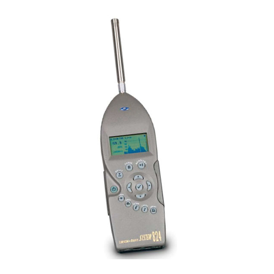
Analyzer and precision sound level meter
Hide thumbs
Also See for System 824:
- Technical reference manual (673 pages) ,
- Reference manual (536 pages) ,
- Training manual (66 pages)
Table of Contents
Advertisement
Quick Links
Download this manual
See also:
Reference Manual
Advertisement
Table of Contents

Related Manuals for Larson Davis System 824


Summary of Contents for Larson Davis System 824
- Page 1 System 824 Training Manual Larson•Davis Inc. 1681 West 820 North Provo, UT 84601-1341 Phone: (801) 375-0177 FAX: (801) 375-0182 www.lardav.com I824.02 March 3, 1998...
- Page 2 System 824 USER MANUAL Copyright Ó Copyright 1997 Larson•Davis, Incorporated. This manual and the software described in it are copyrighted, with all rights reserved. The software may not be copied in whole or in part for commercial use without prior written consent of Larson•Davis Inc. The...
-
Page 3: Table Of Contents
Table of Contents Chapter 1 System 824 Overview General Description ................1-1 User Interface ................... 1-3 Chapter 2 Setup S Simple Sound Analyzer (SSA)............... 2-1 Chapter 3 View V Any Data....................3-1 RTA Live, RTA Max, and RTA Leq ............3-6... - Page 4 System 824 Training Manual Overall SLM ................... 6-18 Modifying the Overall SLM Settings..........6-20 Run Log....................6-21 Time History ..................6-22 Modifying the Time History Settings..........6-22 Viewing Time History Data ............. 6-29 Intervals ....................6-31 Modifying the Interval Settings ............6-32 Viewing Interval Data ..............
-
Page 5: System 824 Overview
This manual is best used accompanied with the instru- ment. You will be guided through a step by step tour of the System 824. The appropriate keypad button will be shown on the page. The resultant 824 display will then be presented to verify that you have performed the correct action. - Page 6 You will likely find the user interface of the System 824 to be very intuitive. However, it is recommended that you initially follow the steps shown in this manual until you have full exposure to the nuances of the instrument’s operating system. It should also be men- tioned that for detailed explanations of the System 824’s functions, you should defer to the System 824...
-
Page 7: User Interface
Step 2 Press l to exit the PWR screen User Interface There are quite a few places you can go from here. It’s worthwhile to discuss the 824 User interface, starting with the instrument keypad. The three keys on the top 2/19/98 System 824 Overview... - Page 8 P - The PRINT key is used to establish the setting required to communicate with an external serial printer. The user also selects the type of report that they wish to print from within this menu. System 824 Training Manual 2/19/98...
- Page 9 The check key c is used to select an option or choice from an 824 menu. It is also used to access the various Settings menus from within the measurement displays (views). 2/19/98 System 824 Overview...
- Page 10 System 824 Training Manual 2/19/98...
-
Page 11: Chapter 2 Setup S
C H A P T E R Setup As mentioned, the SETUP S key is used to establish the 824 measurement setups and associated parame- ters. Press the SETUP S. The setup names in the setup menu screen list will de- pend on the configuration of your 824. - Page 12 If the following screen appears, press the desired choice. In this example, the choice “No” will be selected. Step 3 Press r once to highlight “No” (or what- ever choice you desire) System 824 Training Manual 2/19/98...
- Page 13 The SLM&RTA (SSA) setup is now Step 4 Now press the check key: c to proceed with active denoted by the SLM+RTA the SLM&RTA (SSA) setup recall. If another title at the top of the screen. Notice message appears noting that the Active ID that the SLM characters are bolded.
- Page 14 Step 22 Step 9 To set the time, press TOOLS T to access the clock/timer set feature. Step 10 Press d to highlight “Clock/Timer”. System 824 Training Manual 2/19/98...
- Page 15 Step 11 Press r to enter the “Clock/Timer” menu. Within this menu, you can change the Current Time, Current Date, Day of Week, Timer Mode, Run Date, Stop Date, Run Time 1, Stop Time 1, Run Time 2, and Stop Time 2. For now, we will only worry about setting the time, date, and day of the week.
- Page 16 Use l or r to highlight the number you want to change. Once highlighted, use u or d to increment or decrement the number. Continue this process until you have the desired “Current Date” entered. System 824 Training Manual 2/19/98...
- Page 17 Step 17 Press c to enter the date. Step 18 To change the current “Day Of Week”, press u or d to highlight the “Day Of Week” field. Step 19 Press r to enter the “Day Of Week” modifi- cation field. Step 20 Use d or u to highlight the weekday you want active.
- Page 18 Leq for the current measurement, and the total runtime since the last measurement reset. Within this screen, many useful functions can be accessed using the arrow keys. System 824 Training Manual 2/19/98...
- Page 19 In the SLM View, (on-screen param- Step 23 Press r once and Slow will be highlighted. eter modification) can be performed using the u, d, l, r arrow keys. Step 24 Now press r (or l) and you will cycle through the three detector rate options: Fast, Slow, and Impulse.
- Page 20 SLM (Sound Level Meter) parameters; the RTA (Real Time Analyzer) parameters; the RTA Intervals; the Report settings; and the I/O (input/Output) Controls. Let’s enter the SLM Settings menu. 2-10 System 824 Training Manual 2/19/98...
- Page 21 Step 29 Press u or d highlight SLM. Step 30 Now press c (or r) to enter SLM Settings menu. Here you can see the different parameters that can be changed for the SLM functions of the 824. The parame- ters that can be accessed and modified include the Detector Rate, Weighting, Gain, Transducer (Con- denser microphone, Electret microphone, and Direct),...
- Page 22 SLM measurement views. Step 35 To exit the SLM Settings menu you can either press the left key three times, or press SETUP. For this exercise, press SETUPS. You will be 2-12 System 824 Training Manual 2/19/98...
- Page 23 returned to the SLM + RTA measurement dis- play. 2/19/98 Setup S 2-13...
- Page 24 2-14 System 824 Training Manual 2/19/98...
-
Page 25: View
C H A P T E R View As mentioned earlier, the VIEW key V is used to choose the different types of data that can be viewed using the current measurement setup that you have selected. Press VIEW V. Since we are currently in the SLM&RTA (SSA) setup, the View options will reflect this selection. - Page 26 Now you are viewing the current Step 4 Press r to get to the “Any Level b”screen. Leq and SEL data with the various weighting values applied. System 824 Training Manual 2/19/98...
- Page 27 These are the current Lmax values Step 5 Press r again to get to the “Any Level c”. from the Fast and Slow detectors with the weighting values applied. These are the current Lmin values Step 6 Press r again to get to the “Any Level d” from the Fast and Slow detectors screen.
- Page 28 Lmax from the 824’s impulse detector. Here we see the value, date, and time Step 12 Press r to access the ”Any/Time-d” screen. associated with the Lmin from the 824’s slow detector. System 824 Training Manual 2/19/98...
- Page 29 Now we see the value, date, and time Step 13 Press r to access the “Any/Time-e” screen. associated with the Lmin from the 824’s fast detector. This is the value, date, and time Step 14 Press r to access the “Any/Time-f” screen. associated with the Lmin from the 824’s impulse detector.
-
Page 30: Rta Live, Rta Max, And Rta Leq
RTA Live, RTA Max, and RTA Leq Let’s now explore some of the different ways that we can look at RTA data from the 824. First, make sure that you are in the View menu. System 824 Training Manual 2/19/98... - Page 31 Step 1 Now press d to highlight the “RTA Live” viewing option. Step 2 Press c to accept this View choice. The “SLM+RTA Live” screen is now active as is noted at the top of the display. Notice that RTA is now in bold letters informing us that we are viewing the fractional octave band data from the 824.
- Page 32 1/3 octave band data in tabular for- mat rather than graphic. Step 4 Pressing the left and right arrow keys (l or r) will scroll through all of the frequencies and amplitudes. When you have finished, System 824 Training Manual 2/19/98...
- Page 33 press c again to re-enter the SLM/RTA view- ing options. Step 5 With “Spectrum” highlighted, press c to switch the display back to the graphical for- mat. Step 6 Press c again to re-enter the SLM/RTA view- ing options. Now press d to highlight the “Graph”...
- Page 34 Step 9 Press c twice to return to the SLM/RTA viewing options. Step 10 Now press d to highlight the “Setting” options. Then press c. 3-10 System 824 Training Manual 2/19/98...
- Page 35 Step 11 Now press c to enter Setting. Step 12 Press d to highlight the RTA settings option. Step 13 Next, press c (or r) to enter the RTA set- tings menu. Filters is used to conserve power. Here we can change the settings for the RTA Detector Setting the filter to12.5 KHz is less (Fast, Slow), the fractional octave Bandwidth (1/3, or energy consuming than using 20...
- Page 36 Step 14 Press d until Bandwidth is highlighted. Step 15 Now press c (or r) to enter the Bandwidth menu Step 16 Press u to highlight 1/1. Step 17 Then press c to initiate the bandwidth change. 3-12 System 824 Training Manual 2/19/98...
- Page 37 Step 18 Press l three times to exit the Settings menu and back to View. You will now see the 1/1 octave band data in the graphical display. For purposes of this exercise, let’s change the display back to 1/3 octave bands. We’ll repeat the process we just completed.
- Page 38 Before exploring the other types of setups that you may have in your particular 824, lets explore the other common features with all 824’s. Step 23 Press V to exit back to the SLM+RTA screen. 3-14 System 824 Training Manual 2/19/98...
-
Page 39: Chapter 4 Data D
Data The DATA key D provides access to the data storage and recall functions of the System 824. Data files are stored in the 824’s internal memory. First, verify that the 824 is still running (running figure in top right cor- ner). - Page 40 Step 2 Press c to stop the 824 and store the current data. The 824 will beep to signify that the data storage has occurred, and return the display to the previously active View screen. Step 3 To examine previously stored data, press DATA D. System 824 Training Manual 2/19/98...
- Page 41 Step 4 Notice that the stored data record now appears in the Data Files list. Press d to highlight the stored record. Step 5 To see information on the stored measure- ment, press r. This screen shows the date and time of the measure- ment beginning and end.
- Page 42 Step 7 To recall the previously selected record, use u or d to highlight “Recall Data”. Step 8 Press c to recall the currently selected record. The 824 will beep and the data record will be dis- played. System 824 Training Manual 2/19/98...
-
Page 43: Chapter 5 Tools T
C H A P T E R Tools The TOOLS T key accesses system oriented opera- tions for the 824. These include calibration; setting the 824 clock/timer; checking memory; establishing lock parameters; power monitoring; and setting communi- cations protocol. Press TOOLS T to access the Tools menu. - Page 44 824. It also lists screen. the total RAM (memory) in your unit. Step 4 Press r to return to the “About-a” screen. Step 5 Press TOOLS T to return to the Tools menu. System 824 Training Manual 2/19/98...
- Page 45 This screen contains fields for entering your company, address, and a title. This allows you to “personalize” your System 824. Let’s enter a name in this exercise. The first name field should already be highlighted. If it isn’t, press u or d to highlight the first “Name”...
- Page 46 Continue this process until the name is complete. Note that the scroll list contains upper and lower case letters, numbers, punctuation, and a variety of useful symbols. System 824 Training Manual 2/19/98...
-
Page 47: Calibration
Step 10 Press c to enter this name. Step 11 The other name field can be edited in the same fashion. Press l to return to the Tools menu. Calibration Step 1 From within TOOLS, press d to highlight “Calibration”. 2/19/98 Tools T... - Page 48 Step 4 Next, let’s press r to enter the “Calibration” menu to check and change the calibration val- ues. Step 5 To check the current calibration, confirm that “Check” is highlighted in the Calibration menu. System 824 Training Manual 2/19/98...
- Page 49 Next, connect a microphone calibrator to the 824’s microphone. Then turn the calibrator on. (Note: the calibrator dB output level should match the number associated with “Cal Level” in the Calibration menu. If it does not, skip to “Cal Level” now and change the value to match your calibrator).
- Page 50 “Yes”. The system will go through a calibration change. Step 12 If you are using a condenser microphone (and you have the 824 Option 01 installed), you will be asked if you’d like to “Calibrate the System 824 Training Manual 2/19/98...
- Page 51 High Range?” of the 824. Press c to answer “Yes”. In order to perform high range mea- surements, the 824 reduces the microphone polarization voltage by 20 dB. It will take about one minute for this change (and stabilization) to occur, so that the high range can be calibrated.
-
Page 52: Modifying The Calibration Level
Step 3 Here, use l or r to highlight the number you wish to change. Once highlighted, use u or d to increment or decrement the number. Continue this process until you have the desired “Cal Level” entered. Press c to enter the level. 5-10 System 824 Training Manual 2/19/98... -
Page 53: Clock/Timer
As you probably know, it is good Step 4 Press l to exit the “Calibration” menu. measurement practice to use the same calibrator every time you per- form a calibration check and/or change to your 824. The “Calibrator S/N” is used to enter the serial num- ber of the calibrator that you have designated as your “824 calibrator”. - Page 54 Timer modification by editing the “Current Time”. Day of Week, Timer Mode, Run Date, Stop Date, Run Time 1, Stop Time 1, Run Time 2, and Stop Time 2. These parameters are all changed in a similar way. 5-12 System 824 Training Manual 2/19/98...
- Page 55 Step 7 Press u or d to highlight “Current Time”. Step 8 Press r to enter the “Current Time” modifi- cation field. Step 9 Here, use l or r to highlight the number you wish to change. Once highlighted, use u or d to increment or decrement the number.
- Page 56 Step 12 Use l or r to highlight the number you want to change. Once highlighted, use u or d to increment or decrement the number. Continue this process until you have the desired “Current Date” entered. Press c to enter the date. 5-14 System 824 Training Manual 2/19/98...
-
Page 57: Timer
Step 13 To change the current “Day Of Week”, press u or d to highlight the “Day Of Week” field. Step 14 Press r to enter the “Day Of Week” modifi- cation field. Step 15 Use d or u to highlight the weekday you want active. - Page 58 (uses Run Date, Stop Date, Run Time 1, Stop Time 1, Run Time 2, and Stop Time 2) Step 3 Use d or u to highlight the desired Timer Mode selection. 5-16 System 824 Training Manual 2/19/98...
- Page 59 Step 4 For exercise sake, choose “Block Mode” by using u or d to highlight “Block”. Step 5 Once you have selected the “Block” Timer Mode choice, press c to activate it. Step 6 To change the “Run Date”, first press u or d to highlight the “Run Date”...
- Page 60 Step 9 Press c to enter the run date. For sake of economy, use a short measurement dura- tion in this exercise (one minute). To change the “Stop Date”, first press u or d to highlight the “Stop Date” field. 5-18 System 824 Training Manual 2/19/98...
- Page 61 Step 10 Press r to enter the “Stop Date” modifica- tion field. Step 11 Use l or r to highlight the number you want to change. Once highlighted, use u or d to increment or decrement the number. Continue this process until you have the desired “Stop Date”...
- Page 62 Once highlighted, use u or d to increment or decrement the number. Continue this process until you have the desired “Run Time 1” entered. Step 16 Press c to enter the “Run Time 1”. 5-20 System 824 Training Manual 2/19/98...
- Page 63 Step 17 To change the “Stop Time 1”, press u or d to highlight the “Stop Time 1” field. Step 18 Press r to enter the “Stop Time 1” modifica- tion field. Use l or r to highlight the number you want to change.
-
Page 64: Memory
(using the active measurement setup) until the stop date/time are reached. Press l to return to the “Tools” menu. Memory Step 1 While in the TOOLS menu, press d to high- light “Memory”. 5-22 System 824 Training Manual 2/19/98... - Page 65 The “Memory-a” screen displays the Step 2 Press c to enter the “Memory-a” screen. amount of available memory in your 824. “Memory-b” provides additional Step 3 Press r to advance to the “Memory-b” memory information including the screen. number of data files stored and the available setup allocations.
-
Page 66: Lock
TOOLS T to return to the Tools menu. Lock Step 1 From the TOOLS menu, press d to high- light “Lock”. The “Lock” screen shows the lock Step 2 Press c to enter the “Lock” screen. status of the 824. 5-24 System 824 Training Manual 2/19/98... -
Page 67: Power Monitor
Press TOOLS T to return to the Tools menu. Power Monitor Step 1 While in the TOOLS menu, press d to high- light “Power Monitor”. The “Battery” screen provides infor- Step 2 Press c to enter the “Battery” screen. mation regarding the power source of the 824. - Page 68 Within this menu, you can control Step 7 Press c (or r) to enter the “Settings” menu. the Power Settings parameters. These include “Power Off Mode”, “Auto-Off Time”, “Standby Time”, “Backlight Time”, “Backlight”, “LCD contrast”, and “External Power”. 5-26 System 824 Training Manual 2/19/98...
- Page 69 Step 8 To look at the “Power Off Mode” press u or d to highlight this choice. The “Blank LCD” selection will Step 9 Now press c (or r) to enter the “Power Off cause the LCD screen to turn off, Mode”...
- Page 70 Step 12 Once you have established a desired “Auto- Off Time, press c. Step 13 Now press d to highlight “Standby Time”. 5-28 System 824 Training Manual 2/19/98...
- Page 71 “Standby Time” places the 824 in an Step 14 Press c (or r) to enter the “Standby Time” energy conservation state by turning menu. off the LCD (screen), the serial port, and the DC output, while still gath- ering data. Here you establish the “Standby Time”...
- Page 72 The u and d arrow keys increment through the minute numbers, while l and r toggles between to minute fields. Step 18 Once you have established a desired “Back- light Time, press c. Step 19 Now press d to highlight “Backlight”. 5-30 System 824 Training Manual 2/19/98...
- Page 73 The “Backlight” screen provides Step 20 Then press c (or r) to enter the “Backlight” another means of enabling or dis- menu. abling the backlight function. Step 21 Use u or d to establish your backlight choice. Press c to activate this selection. Step 22 Now press d to highlight “LCD Contrast”.
- Page 74 824. Choosing “Battery” is the proper choice if you plan to power the 824 from an external 12-Volt battery (lead acid for example). Please consult Larson Davis regard- ing the proper method of connecting the 824 to the external battery.
- Page 75 Step 27 Use u or d to establish your external bat- tery choice. Press c to enable this selection. Step 28 Press l to exit the “Power Settings” menu and return to the “Power” Menu. Step 29 Now let’s press d to highlight “Charge Mode”.
-
Page 76: Communication
Step 31 Use u or d to establish your battery charge choice. Press c to enable this selec- tion. Step 32 Press l to return to the Tools menu. Communication Step 1 From within the TOOLS menu, press d to highlight “Communication”. 5-34 System 824 Training Manual 2/19/98... - Page 77 The screen becomes active during Step 2 Press c to enter the “Communication” serial communication with a com- screen. puter. You can monitor the commu- nication process within this window. Here, you can establish and modify Step 3 Now, press c again to enter the “Serial Com- the parameters associated with com- munication”...
- Page 78 Step 8 Use the u and d arrow keys increment through the address numbers, while l and r toggles between the three address fields. Press c when you have selected the desired address. 5-36 System 824 Training Manual 2/19/98...
- Page 79 Step 9 Now press d to highlight “Flow Control”. Within this menu, you can select the Step 10 Press c (or r) to enter the “Flow Control” method of handshaking appropriate menu. for the device which you plan to com- municate with.
- Page 80 5-38 System 824 Training Manual 2/19/98...
-
Page 81: Log - Logging Sound Level Meter (Option 01)
C H A P T E R Log - Logging Sound Level Meter (Option 01) Your 824 does not necessarily contain the Log option. This is a non-standard option that is purchased sepa- rately from the basic Model 824. If you indeed have purchased this option, proceed. -
Page 82: Current Slm
It should be noted that “Cur- rent” means the data since the last RESET R. If the 824 is not currently running, press RUN/STOP s to start a measurement. System 824 Training Manual 2/19/98... - Page 83 Step 3 The current data can be witnessed by per- forming a data reset. Press RESET R. Notice that the run time clock is set to 00:00:00 and restarts when the reset is performed. The screen lists the date and time Step 4 Now press r to see the “SLM Current-b”...
-
Page 84: Modifying The Slm Settings
For this exercise, use the shortcut. Step 1 From within the “SLM Current” window, press c. You are now viewing the SLM setting screen. From here, you can modify the various parameters associ- System 824 Training Manual 2/19/98... - Page 85 ated with the 824 Sound Level Meter functions. The “Graph” settings operate the same as was shown ear- lier in the Simple Sound Analyzer (SSA) section. Step 2 For review, first verify that “Graph” is high- lighted. Step 3 Now press c to activate the “Adjust Graph” feature.
- Page 86 SLM Current-a screen. Step 6 Press c to return to the “SLM Settings” win- dow. Step 7 Now press d to highlight “Settings”. Step 8 Press the check key c to enter Settings menu. System 824 Training Manual 2/19/98...
- Page 87 The parameters that can be modified Step 9 Press u or d to view the different parame- here include: SLM Detector (Fast, ters that can be changed for the current SLM Slow), SLM Weighting (A,C, Flat), setup. For this exercise, press d until Pk Range (Normal, Low, High), Trans- Weighting is highlighted.
- Page 88 Step 14 Press lto return to the SLM Settings menu. We will look at the TWA settings when we cover the Exposure features of the 824. Step 15 Press l to exit the SLM Settings menu. System 824 Training Manual 2/19/98...
-
Page 89: Stats
Stats Displayed here are the current set- Step 1 Press u to move to the SLM Stats screens. tings of the SPL exceedance thresh- Immediately shown is the “SLM Stats-a” olds, with the number of times that screen. these values have been surpassed during the current measurement. -
Page 90: Modifying The Stat Settings
You can set two exceedance levels for the SPL detector, and two exceedance levels for the Peak detector. Step 2 For this exercise, change the Peak 1 level. Press d until “Pk-1 Excd Lvl” is high- lighted. 6-10 System 824 Training Manual 2/19/98... -
Page 91: Ln Centiles
Step 3 Press r to enter the “Pk-1 Excd Lvl” screen. Step 4 The u and d arrow keys increment through the exceedance level numbers, while l and r toggles between the three numeric fields. Once you have selected a desired “Pk-1 Excd Lvl”... -
Page 92: Modifying The Ln Settings
To change the values of the six Ln settings for the SLM, you can again go to the SETUP menu by pressing S, or you can take the shortcut from where you are cur- rently. Once again, take the shortcut. 6-12 System 824 Training Manual 2/19/98... - Page 93 Step 1 From within the “SLM Ln” window, press c. The “Graph” settings operate the same as was shown earlier in the “SLM Current” section. We will skip that feature now. Press d to highlight “Settings”. Step 2 Then press r to enter to the “Ln” setting screen.
- Page 94 Step 5 The u and d arrow keys increment through the percentage numbers, while l and r toggles between the different numeric fields. Step 6 Once you have selected a desired “Ln 3” value, press c. 6-14 System 824 Training Manual 2/19/98...
-
Page 95: Exposure
Step 7 The new “Ln 3” value now appears in the associated field. Press l to exit the “Ln” screen. Step 8 Press l again to return to the “SLM Ln” dis- play window. Exposure This screen shows the Dose and Pro- Step 1 Press u to move to the SLM Exposure-a jected Dose. -
Page 96: Modifying The Exposure Settings
These include the Overall Exchange Rate, Overall Threshold Level, Overall Criterion Level, and the Criterion Time. 6-16 System 824 Training Manual 2/19/98... - Page 97 Step 2 For sake of exercise, let’s change the exchange rate. Use u or d to highlight “Ovll Exchange”. Step 3 Press r to enter the “Ovll Exchange” win- dow. Step 4 The following warning will appear letting you know that a measurement reset is required if the exchange rate is going to be altered.
-
Page 98: System 824 Training Manual
“Overall” is different from “Cur- rent”. Recall that “Current” shows only the data since the last RESET R. “Overall” is unaffected by a RESET and is the accumulated data from the original start of the mea- surement. 6-18 System 824 Training Manual 2/19/98... - Page 99 This screen lists the date and time Step 2 Press r to see the “SLM overall-b” screen. when overall measurement began, along with the current date and time if the measurement is run- ning (stop date and time if it is not running), and the elapsed run time.
-
Page 100: Modifying The Overall Slm Settings
“Stats”. We accessed these by toggling the u and d arrow keys while we were in the measurement display (recall that we started with “SLM Current”). Let’s look at the rest of them now. 6-20 System 824 Training Manual 2/19/98... -
Page 101: Run Log
Run Log Step 1 Press d to highlight the “Run Log” View selection. The Run Log provides a record for Step 2 Then press c (or r) to select “Run Log”. each 824 measurement run and stop. In other words, it keeps a record of every time the RUN/STOP key s has been pressed since the last Over- all RESET. -
Page 102: Time History
Modifying the Time History Settings To change the Time History parameters, you can choose to go to the SETUP menu by pressing S, or you can take the shortcut from where you are cur- rently. 6-22 System 824 Training Manual 2/19/98... - Page 103 The choices within the “Time His- Step 1 From within the “SLM Time History” win- tory” menu include: “Beginning”, dow, press c. “Ending”, “Find”, “Graph”, and “Settings”. “Beginning” moves you to the first Time History sample of the active measurement. “Ending” moves you to the last Time History sample of the active measurement.
- Page 104 Step 6 The choices are “Yes” or “No”. Use u or d to highlight “Yes”. Then press c to enter your choice. “Hist Period” is used to establish the duration of each Time History sample. Step 7 Press u or d to highlight “Hist Period”. 6-24 System 824 Training Manual 2/19/98...
- Page 105 Step 8 Press c (or r) to enter the “Hist Period” screen. The u and d arrow keys increment through the Period Time values, while l and r toggles between the different numeric fields. Step 9 Let’s set the 824 to acquire 10 second time his- tory samples.
- Page 106 Leq. The choices include “none”, “Pk- 2”, “Pk-1”, “Lmax”, and “Advc”. Here. Step 13 Let’s choose Lmax as our other measurement to be logged. Press u or d to highlight “Other Level”. 6-26 System 824 Training Manual 2/19/98...
- Page 107 Step 14 Press c (or r) to enter the “Other Level” screen. Step 15 Use the u or d arrow keys to highlight Lmax as the other level to be logged with the Time History of the Leq. Then press c to enter this selection.
- Page 108 Step 19 Now press l to exit the Time History “Set- tings” menu. Step 20 Next, press l to return to the Time History display. There is no data because the acquisi- tion parameters have changed. 6-28 System 824 Training Manual 2/19/98...
-
Page 109: Viewing Time History Data
Viewing Time History Data Step 1 Press s to initiate the measurement. On the screen you will see a graph of Step 2 After the measurement has run for a brief the Leq versus time. The display also duration (minute or so), press l or r (or lists the value of the Leq (larger digi- u or d ) to cycle through the time history tal number), and the “other level”... - Page 110 Step 6 Press c to accept the reset. Step 7 Now let’s disable the time history logging feature. Press u to highlight “No”, then press c to accept. 6-30 System 824 Training Manual 2/19/98...
-
Page 111: Intervals
Step 8 Now press l to return to the Time History “Settings” menu. Step 9 Press l again to return to Time History view. Step 10 Push VIEW V to return to the View window. Intervals Intervals is very useful when moni- Step 1 Within VIEW, press u or d to highlight toring noise levels for extended peri- “Intervals”. -
Page 112: Modifying The Interval Settings
SETUP menu by pressing S, or you can take the shortcut from where you are currently. Step 1 From within the “SLM Interval” window, press c. Step 2 Press d to highlight “Settings”. 6-32 System 824 Training Manual 2/19/98... - Page 113 The choices here are: “Intv Enable”, Step 3 Next, press c (or r) to enter the “Interval” “Intv Period”, “Intv Time Sync”, settings menu. “Intv Save Ln’s”, “Intv Auto Stop”, “Intv Threshold, “Intv Exchange”. The “Intv Enable” acti- vates or deactivates the Intv mea- surement function.
- Page 114 Interval time values, while l and r toggles between the different numeric fields (hh:mm:ss). Step 9 Now enter our one minute interval choice by selecting “00:01:00” After you have entered this “Intv Period”, press c to enable this selection. 6-34 System 824 Training Manual 2/19/98...
- Page 115 “Intv Time Sync” enables or disables Step 10 Press u or d to highlight “Intv Time the capability of synchronizing the Synch”. measurement interval with the 824’s built-in clock. An example would be if you wanted to have an interval stored every hour, on the hour.
- Page 116 Stop”. after each Interval is complete. The next Interval will then begin only when the RUN/STOP key s is pushed. Step 17 Now press c (or r) to enter the “Intv Auto Stop” screen. 6-36 System 824 Training Manual 2/19/98...
- Page 117 The choices are “Yes” or “No”. Use u or d to high- light your “No”. Step 18 Then press c to enter this choice. “Interval Threshold” lets you select Press u or d to highlight “Interval Threshold”. a threshold or level for calculating an Interval TWA (Time Weighted Aver- age).
- Page 118 Step 21 Press c (or r) to enter the “Interval Exchange” menu. Step 22 The u and d arrow keys increment through the exchange rate choices. Let’s use a 3 dB exchange rate for now. Once you have highlighted this preference, press c. 6-38 System 824 Training Manual 2/19/98...
-
Page 119: Viewing Interval Data
Step 23 Press l to return to the “Interval” settings menu. Step 24 Press l again to enter the “Interval” mea- surement screen. Viewing Interval Data This is the Interval-a screen. It Step 1 Press RUN/STOP s to initiate the measure- shows the Leq and SEL for the first ment. - Page 120 Here we see the six Ln statistical Step 5 Press r to advance to the “Interval-e” descriptors for the first interval. screen. 6-40 System 824 Training Manual 2/19/98...
-
Page 121: Exceedance History
In the upper right part of the display Step 6 Press r to return to the “Interval-a” screen. (to the right of 1/) you can see the number of one minute intervals that have occurred since the measure- ment was initiated. Step 7 You can view the other interval data by press- ing d. -
Page 122: Modifying The Exceedance History Settings
“Find” lets you choose an Exceed- ance record to move to within the active measurement “Settings” is the area where you can modify the parameters associated with acquir- ing the Exceedance records. 6-42 System 824 Training Manual 2/19/98... - Page 123 Step 3 Press the rto enter the “Excd Settings” menu. This menu lets you to set an exceed- Step 4 Press the u or d to highlight the “Trigger- ance threshold level. When the 824 ing”, then press the c. measures a level that surpasses the established threshold level, it will log the exceedance history.
- Page 124 80 dB (SPL Excd Lvl 1 minus Hys- Step 8 Let’s set the “Hysteresis” to 5. Press r to teresis), the 824 will stop gathering enter the “Hysteresis” window. data, and re-arm its trigger for the next exceedance event. 6-44 System 824 Training Manual 2/19/98...
- Page 125 Step 9 Use u to increment the hysteresis value to 5 dB, then press c to enter this choice. Step 10 Press the lto return to the “Excd Settings” menu. Press u or d to highlight “Excd Enable”. Step 11 “Excd Enable” activates or deactivates the exceedance gathering feature.
- Page 126 fields. Enter 5 sec- onds. Then press c. Step 16 Next, push u and d to highlight “Excd Time-Hist”. With this menu item set to “Yes”, a time history of the event will be saved when 6-46 System 824 Training Manual 2/19/98...
- Page 127 an exceedance event occurs. Let’s set this field to “Yes”. Step 17 Press c to enter the “Excd Time-Hist” menu. Step 18 Now use u or d to select “Yes”. Then press c to accept this choice. Step 19 Press u and d to highlight “T.H. Period”. This menu establishes the sampling rate for time history data acquired during the exceed- ance event.
- Page 128 “Level” or “Passby” as a means of ger”. triggering the exceedance data cap- ture. Passby incorporates the 10 dB down-points exceedance acquisition. (see user manual for details on Passby). Step 23 Press c to enter the Excd Trigger menu. 6-48 System 824 Training Manual 2/19/98...
- Page 129 Step 24 For this example, we will use “Level”. Press u or d to highlight “Level”. Then, press c to activate this selection. Step 25 Now, press u or d to highlight “Excd Time”. Step 26 Then, press c to enter the “Excd Time” menu.
-
Page 130: Viewing Exceedance History Data
You event started are logged. At the bot- should see a “Excd-a” screen similar to the tom of the screen, the total duration one below. of the exceedance event is listed. 6-50 System 824 Training Manual 2/19/98... - Page 131 This display shows the Peak 1, Peak Step 2 Press r to advance to the “Excd-b” screen. 2, and Lmax values for the exceed- ance event. Step 3 Press l or r to return to the “Excd-a” screen. Again, the Leq and SEL of the event, Step 4 Go ahead and create another noise event to and the time and date of the start are initiate one more exceedance event.
- Page 132 “SLM Current” sec- tion. You can control the graph level and scale of the Exceedance Time History using this feature. “Settings” is the area where you can modify the parameters asso- 6-52 System 824 Training Manual 2/19/98...
-
Page 133: Spectra Intervals
ciated with acquiring the Exceedance Time History measurement. Spectra Intervals The Log option also adds the very useful feature of automatically collecting 1/3 or 1/1 octave band spec- tra over time to the Simple Sound Analyzer (SSA). You can capture and store data as fast as 1 spectrum per second. - Page 134 Step 4 Next, press the c to enter the Interval setup menu area. Step 5 Next, press d to highlight “Settings” Step 6 Press c to enter Interval “Settings”. Step 7 Press d to highlight “Settings. 6-54 System 824 Training Manual 2/19/98...
- Page 135 Step 8 Next, press c (or r) to enter the “Interval” settings menu. Step 9 Now press c (or r) to enter the “Intv Enable” screen. Step 10 The choices are “Yes” or “No”. Use u or d to highlight “Yes”. Then press c to enter your choice.
- Page 136 fields (hh:mm:ss). Step 13 Now enter a ten second interval choice by selecting “00:00:10”. Step 14 Press c (or r) to enter the “Intv Period” screen. Step 15 The l twice to exit Interval Settings. 6-56 System 824 Training Manual 2/19/98...
-
Page 137: Viewing Spectra Intervals
Viewing Spectra Intervals After you have enabled the Interval setup parameters, press VEIW V to access the Simple Sound Analyzer (SSA) View menu Step 1 Press d to highlight “Leq Spectra”. Step 2 Press c to activate this View selection. 2/19/98 Log - Logging Sound Level Meter (Option 01) 6-57... - Page 138 Step 5 Now let’s look at the Max spectra for each interval. Press View V to return to the View screen Step 6 Press d until you have highlighted the “RTA MAX” selection. 6-58 System 824 Training Manual 2/19/98...
- Page 139 The Max spectra is the frequency Step 7 Press c to view the Interval Max spectra spectrum that contains the largest amount of acoustic energy that occurred during the measurement interval. As you increment through the logged Max spectra, you can see the interval number at the top, left part of the screen.
- Page 140 6-60 System 824 Training Manual 2/19/98...
- Page 141 Index Numerics viewing 6-50 Exceedance Levels 6-10 1/1 octave 3-13 Exceedance Threshold 6-43 Exchange Rate 6-17 About External Battery 5-33 screens 5-2 External Power 5-32 Adjust Graph 6-5 Any Data 3-1 Files Any Level 3-2 Data 4-3 Auto-Off Time 5-27 to 5-28 Flow Control 5-37 Frequency Backlight 1-3...
- Page 142 Taktmaximal 3-2 External Power 5-32 Time History 6-22 LCD Contrast 5-31 periods 6-29 Power Off Mode 5-27 settings 6-28 Standby Time 5-28 Timer Mode 5-12, 5-16 Power Monitor 5-25 Titles Power Off Mode 5-27 Index-2 System 824 Training Manual 2/26/98...
- Page 143 user 5-3 Tools key 5-1 Lock 5-24 memory 5-22 Power Monitor 5-25 TWA 6-19 User titles 5-3 User interface 1-3 View Any Data 3-1 Current SLM 6-2 Spectra Intervals 6-57 Viewing Exceedance History 6-50 Viewing Interval Data 6-39 Index-3 2/26/98...
Need help?
Do you have a question about the System 824 and is the answer not in the manual?
Questions and answers