Table of Contents
Advertisement
Advertisement
Table of Contents

Related Manuals for Larson Davis 831


Summary of Contents for Larson Davis 831
- Page 1 Model 831 Sound Level Meter Manual...
- Page 2 Larson Davis Model 831 Manual I831.01 Rev O Manual...
- Page 3 Changes and improvements to the information described in this manual may be made at any time. Record of Serial Number and Purchase Date Model 831 Serial Number: ___________ Preamplifier Model: _________...
-
Page 4: Table Of Contents
Unpacking and Inspection ..................2-1 Connecting the Microphone and Preamplifier ............2-2 Connecting the Preamplifier ................. 2-3 Disconnecting the Preamplifier ................2-4 Powering the Model 831 ..................2-4 Chapter 3 Overview 831 Components ....................3-1 Summary of Displays and Icons ................3-7 Navigating and Selecting .................. - Page 5 Run Modes Without Measurement History ............6-4 Chapter 7 Making a Measurement Configuration of the System ..................7-1 Switching On the Model 831 .................7-1 Model 831 Setup ....................7-3 Calibrating the Model 831 ..................7-3 Positioning the Model 831 ..................7-3 Performing the Measurement ................7-5 Storing the Measurement ..................7-15...
- Page 6 Locate Record Number ..................11-16 Link to Measurement History Display .............. 11-17 Markers ......................11-18 Chapter 12 Measurement History 12-1 Run Control with Measurement History ............. 12-1 Continuous and Timer Modes ................12-2 Timed Stop Mode ....................12-3 Manual and Stop When Stable Modes ..............12-5 Display of Measurement History Data ..............
- Page 7 Localization .......................18-20 Displays ......................18-23 Options .......................18-29 Logic I/O ......................18-31 Chapter 19 Non-Acoustical Inputs 19-1 831-INT .......................19-1 Weather Measurement Using 831-INT ...............19-2 Location Measurement Using 831-INT .............19-10 Chapter 20 Communication 20-1 Control Panel - Communication ................20-1 Modem Tab ......................20-3 Wireless Tab ......................20-6 RS-232 Tab ......................20-8...
- Page 8 21-1 Control Panel - Lock ................... 21-1 Fully Locked ....................... 21-5 Locked With Auto-Store ..................21-6 Locked With Manual-Store ................. 21-7 Calibration When The Model 831 Is Locked ............21-8 Chapter 22 About 22-1 Control Panel - About ..................22-1 About ........................
- Page 9 SLM Utility-G3 ....................26-1 Upgrading Model 831 Firmware .................26-2 Upgrading Options ....................26-7 Appendix A Technical Specifications Standards Met by Model 831 ................A-1 Model 831 Specifications ..................A-2 CE Information ....................A-20 1/1 and 1/3 Octave Filters ................... A-21 Position of Instrument and Operator ..............A-30 Frequency Response ...................
-
Page 10: 831 Features
C H A P T E R 831 Features Welcome to the Larson Davis Model 831. This versatile instrument, with graphic display, performs the functions of several instruments; It puts the combined features of a precision sound level meter and a real-time frequency analyzer in the palm of your hand. -
Page 11: Basic Measurements
USB 2.0 full speed peripheral connector for control and data download by a PC • AUX control connector for USB remote power, weather transducers and the 831-INT • I/O connector for communicating with peripheral devices such as weather transducers •... -
Page 12: Available Options
Automatic Data Logging with periods from 20 ms to 24 hour (831-LOG) • Fast Spectral Time History Data Logging with intervals of 2.5, 5.0 or 10 ms (831-FST, requires 831- LOG and 831-OB3) • Exceedance-based Logging Analysis with Events (831-ELA). Automatic sound recordings can also be made when the 831-SR option is also enabled •... -
Page 13: Standard Accessories
Temperature, Humidity (831-WTHR) • Analog Modem or RS-232 Communication (831-MDM) Standard Accessories Some of these options may not be The Model 831 is generally delivered with the standard provided with systems designed for accessories described below. specific applications. Microphone Preamplifier •... -
Page 14: Optional Accessories
TRP003 • EPS2108-2 Environmental Shell, protects microphone and preamplifier from rain and wind and used with tripod TRP002 • EPS029-831 Weather-proof enclosure for remote noise monitoring; includes two batteries and microphone mast Model 831 Manual Optional Accessories... - Page 15 EPS033 Steel security band for NMS systems • NMS016 Permanent noise monitoring system with weather proof enclosure and tilt down pole designed for AC power; includes Model 831, EPS031, 831-INT, 17' pole, 426A12, 9-AH backup battery and fiberglass enclosure •...
- Page 16 •BAT012 100AH Battery •BAT013 2X21AH batteries Weather Data Acquisition • 831-INT 831 Interface Unit for use with 426A12 Outdoor Microphone Preamplifier and weather sensors The SEN028, SEN029, and SEN030 • SEN028 Wind Monitor; Speed and Direction are no longer supported.
- Page 17 Model 831 in conjunction with CBL140, CBL145 or CBL154. 1.25 A, 2.5X5.5X14 mm • BAT015 External battery powering device for the 831, holding 4 or 8 D-sized alkaline 1.5 volt batteries to extend run time Optional Accessories Model 831 Manual...
- Page 18 TRP020-06 Heavy duty 6' tripod. Use with 426A12, with EPS031 AND EPS032. EPS030-831 AND EPS029-831 • TRP020-10 Heavy duty 10' tripod. Use with 426A12, EPS030-831, EPS029-831, EPS031 and EPS032 • TRP020-15 Heavy duty 15' tripod. Use with 426A12, EPS030-831, EPS029-831, EPS031 and EPS032 •...
- Page 19 • DNA (Data Navigation and Analysis) software provides setup and remote operation of the Model 831, providing real-time data displays on a PC. Powerful graphics routines are provided to create custom data displays ranging from simple time histories and frequency spectra to spectrograms (level...
-
Page 20: First Use
• Using USB power • Powering-up the Model 831 You will then be ready to use the Model 831 for actual measurements. Unpacking and Inspection Your Model 831 has been shipped in protective packaging. Please verify that the package contains the items listed below. -
Page 21: Connecting The Microphone And Preamplifier
The microphone body will seat smoothly against the preamplifier body. DO NOT use excessive force. When removing the microphone, turn while gripping the microphone body, not the grid cap, to prevent damage to the microphone diaphragm. Connecting the Microphone and Preamplifier Model 831 Manual... -
Page 22: Connecting The Preamplifier
The bottom end of the preamplifier has a 5 pin connector the collar/ring at the top of the that fits snugly into the top of the Model 831. Insert the Model 831 body. preamplifier into the mating connector on the Model 831. -
Page 23: Disconnecting The Preamplifier
Disconnecting the Preamplifier On the front surface of the Model 831, just below the preamplifier connector, is a small button. Press and hold this button while pulling the microphone / preamplifier assembly out of the Model 831. Preamplifier Release FIGURE 2-4 Push Button to Release Preamplifier... - Page 24 Battery Power The Model 831 is compatible with AA nickel metal hydride (NiMH), Alkaline or 1.5 Volt Lithium batteries. Energizer, Duracell and other nationally recognized brands are the preferred suppliers of alkaline batteries. These will provide the user with the best battery life estimation. Sanyo,...
- Page 25 The unit will shut down in a short time because the battery voltage is too low. When the battery is at the end-of-life, the Model 831 will stop running, save all data and instrument status, then turn off.
- Page 26 Properties, as described in the section “Battery Type” on page 18-5. Charging Batteries On-board When using NiMH batteries and powering the Model 831 from either the computer (via USB port) or from the PSA029 power supply, or from another external source, the batteries will be charged inside the instrument.
-
Page 27: External Power Supply
USB power regardless of negotiation. The PSA029 is supplied with power The Model 831 can be powered via the USB port with the plug adaptors for most areas of the PSA029 external power supply. The PSA029 has an input world. - Page 28 Low Voltage Shutdown The Model 831 has a special feature to preserve the service life of an external SLA (Sealed Lead-Acid) battery by preventing it from being discharged excessively. When the battery voltage drops below the external shutoff voltage (default value +10.8 volts), but remains above +10.2 volts for one minute, the instrument will stop, save data and turn the Model 831 off.
- Page 29 If the power fault condition is not alleviated within 2 minutes, the instrument powers off. If a sufficient power supply is provided for more than 10 seconds, i.e. USB or Main power is connected, the instrument proceeds to turn 2-10 Powering the Model 831 Model 831 Manual...
- Page 30 8 and 2 keys. The units of the temperature display The last section displays the Model 831 internal temperature are user-selectable, as described in that is used to automatically adjust the contrast of the display “Units”...
- Page 31 The real-time clock will maintain its value for six minutes, permanent damage may occur. Press enough to implement a battery change. This prevents battery key for several seconds to drain when the Model 831 is not in use for an extended weeks) turn off the meter.
-
Page 32: Chapter 3 Overview
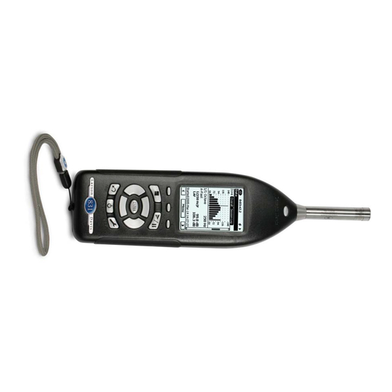
831 Components Microphone Preamplifier LCD Display Keypad Connectors FIGURE 3-1 The Model 831 The standard Model 831 shown in FIGURE 3-1 includes the following: • 1/2 in. diameter condenser microphone • PRM831 microphone preamplifier • Backlit graphic 160 x 240 pixel LCD display •... - Page 33 AC/DC output, control, USB, and external power connectors (shown in FIGURE 3-2) • True “hand held” instrument with “sure grip” pads FIGURE 3-2 shows the bottom view of the Model 831. AC/DC Output and Headset Hardware Power Switch USB Interface AUX Connector...
- Page 34 There are two equivalent electrical impedance adaptors available. These are discussed in Chapter 1 "Optional Accessories" on page 1-5. Display The Model 831 has a 160 x 240 graphic, liquid crystal greyscale display. The display is backlit to provide Model 831 Manual 831 Components...
- Page 35 Controls provided contrast backlight adjustments. When the Model 831 is first switched ON, the Live tab appears. When a measurement is in progress, a display similar to Figure 3-3 is shown. Input Overload or OBA Overload or Under Range Icon...
- Page 36 Keypad The 831 meter has a 13 button keypad. This section describes the buttons on the keypad. FIGURE 3-4 shows the 831 keys. SOFTKEYS: Left Center Right RUN/PAUSE STOP/STORE RIGHT LEFT DOWN TOOLS RESET POWER FIGURE 3-4 Model 831 Keys...
- Page 37 The ten remaining keys below the softkeys are described in Table 3-1. The POWER key is used to turn the Model 831 ON and OFF when the Hardware Power Switch, on the base of the unit is in the “|” position. To turn the 831 off or on, press and hold the power key for a few seconds.
-
Page 38: Summary Of Displays And Icons
Power Indicator The following icons indicate the power source driving the Model 831 and the supply available to operate it. Battery Power The battery icon indicates the state of the battery charge by the width of the interior shaded portion. - Page 39 The external power connection icon appears when the Model 831 is powered from an external power supply or via the USB port. Measurement Name This is the file name to be used for the data file. Stability Indicator Presented in the form of an analog display, this dynamic icon indicates the trend in the measured overall Leq, indicating if the measured signal is rising, decaying or holding stable.
- Page 40 FIGURE 3-7 Normal vs Under Range Data Display OBA Overload Icon If the input to the Octave Band Analyzer (optional firmware 831-OB3 required) becomes overloaded, the icon shown will appear to indicate the overload. This icon operates similar to the Input Overload Icon shown in the above section "Input Overload Icon".
- Page 41 Figure 3-8. FIGURE 3-8 OBA Under Range Display Measurement Status Reset Icon The Reset Icon indicates that a reset has occurred. 3-10 Summary of Displays and Icons Model 831 Manual...
- Page 42 Copy Indicator Icon is displayed in the upper left corner in place of the PCB Piezotronics logo. Power Save Icon When the Model 831 is in the power save mode, the power save icon will be displayed in the location where the measurement status icons usually appear.
-
Page 43: Navigating And Selecting
(STOP/STORE) key. Pressing the key when the unit is PAUSED continues the run. This key is only active on a Data View screen. 3-12 Navigating and Selecting Model 831 Manual... -
Page 44: Tab And Setting Displays
Press the Center Softkey to return the Data Display tabs. Control Panel (Tools) Properties The Control Panel is accessed by pressing the (TOOLS) key at the lower right of the 831 front panel. To exit from the Model 831 Manual Tab and Setting Displays 3-13... -
Page 45: Chapter 6 Run Control
Session Log: The Session Log is a record of data tabs corresponds to the LD default accumulation actions. Resetting and storing data will setup used when the Model 831 is clear the session record. A time-stamped record is made delivered from the factory. These... - Page 46 Additional tabs appear in different instrument modes when the 831-FFT and 831-RT options are enabled. For more information, refer to the "FFT and Tonality" and "RT-60" chapters. Measurement Settings Tabs The Measurement Settings tabs allow for specific settings.
- Page 47 Sound (optional): used to set the quality of sound recording and enable its usage • Weather: used to setup external transducers for the measurement of wind speed, wind direction, temperature and humidity 3-16 Tab and Setting Displays Model 831 Manual...
- Page 48 For a detailed description of the The Control Panel displays icons to represent the different Tools Screen, see “Control Panel - functions available for the Model 831. Pressing the System Properties” on page 18-1. (TOOLS) key displays the Control Panel screen, as shown in FIGURE 3-10.
- Page 49 System Property tabs. Lock For a detailed description of the Lock permits the Model 831 to be configured such that Lock feature, see Chapter 21 " L ock/ certain keys are locked so their functionality cannot be Unlock the Model 831" on page 21- utilized.
- Page 50 The About tabs include the following: • About: shows information such as serial number and firmware revision • Standards: lists the standards that the Model 831 meets • Options: shows the options that are available in this instrument • User: user entered instrument identification...
-
Page 51: Parameter Selection
• Format USB Parameter Selection When operating the Model 831, you frequently define parameters by selecting them from lists that may appear on the display either as a row with a radio button, or as a vertical list in a drop down menu. - Page 52 Use the 2 and 8 keys to highlight the parameter (Frequency Weighting, Detector, etc.), then the 6 and 4 keys to highlight the desired selection for that parameter. Press to make the selection and fill in the radio button associated with that parameter. Model 831 Manual Parameter Selection 3-21...
- Page 53 FIGURE 3-15. FIGURE 3-15 Drop Down Menu Use the 2 and 8 keys to highlight the desired item in the list and press to make the selection and close the menu. 3-22 Parameter Selection Model 831 Manual...
- Page 54 The 6 and 4 keys are used to move the cursor right or left, respectively. At any cursor position, the 8 and 2 keys are used to scroll the alphanumeric character appearing in that position through a defined sequence. Model 831 Manual Parameter Selection 3-23...
- Page 55 When a purely numeric parameter is being entered, as in FIGURE 3-18, the same procedure is followed as for alphanumeric parameters. In this case, repeated presses of the 8 and 2 keys will scroll upward or downward, respectively, through the numeric sequence. 3-24 Parameter Selection Model 831 Manual...
-
Page 56: Chapter 4 Basic Measurement Setup
C H A P T E R Basic Measurement Setup This chapter describes the setup of the Model 831 to perform basic sound level measurements. These measurements may include the following: • Leq, Lmax, Lmin corresponding to user-selected values of frequency weighting and detector •... -
Page 57: Setup Tabs
Settings In Use Message If the Model 831 is not connected to If the G4 is connected to the Model 831 when attempting to a computer running G4 LD Utility access the Settings Screen, the display shown in FIGURE 4- software, ignore this section. - Page 58 General Tab FIGURE 4-3 General Tab The 831 Utility Software can be used The General Tab is used to enter a file name and a to easily enter both the file name and measurement description for the measurement being the measurement description.
- Page 59 Frequency Weighting A, C and Z frequency weightings are provided for the SPL and peak detectors. These are selected separately. Time Weighting Available time weightings for the SPL detector are: Slow, Fast and Impulse. Setup Tabs Model 831 Manual...
- Page 60 0 dB The effect of the gain on the noise level is shown in FIGURE A-27 "Noise of Model 831 with 377B02: 0 dB Gain, Low Range” on page A-48, FIGURE A-28 "Noise of Model 831 with 377B02: 0 dB Gain, Normal Range”...
- Page 61 The effect on the A-Weighted linearity range is shown in the section “f) Linear Operating Range” on page B-9. Octave Band Analyzer Tab (Optional) default values these This tab will only appear when the Model 831 has the parameters shown optional 831-OB3 firmware enabled. FIGURE 4-5. FIGURE 4-5 OBA Tab OBA Parameter Selection The OBA parameters are selected as shown in FIGURE 4-6.
- Page 62 In order to be able to calculate Ln values, the Model 831 creates an amplitude distribution table over the range 0 to 200 dB, in amplitude increments of 0.1 dB. These data...
- Page 63 00.01 to 99.99%. Selection of Ln Values default values these The Model 831 displays six Ln values at a time, using user- parameters shown selected values of n. These are set from the Ln Tab, shown FIGURE 4-7. in FIGURE 4-7.
- Page 64 The selection of the Run Mode and the associated parameters is shown in FIGURE 4-9. The Measurement History feature is not discussed in this chapter. For further information on that, see Chapter 12 "Measurement History” on page 12-1. Model 831 Manual Setup Tabs...
- Page 65 History” a measurement option provided when the optional firmware page 12-1. 831-ELA is enabled. Since this chapter is concerned only with basic measurements, we do not address Measurement History here. Thus, in the following sections when we refer to parameters, this does not include Measurement History.
- Page 66 The Triggers tab is used to define trigger levels associated with exceedance events; instances where the measured sound level (SPL or Peak) exceeds one of the user-defined trigger levels. The variation of sound level during a typical Model 831 Manual Setup Tabs 4-11...
- Page 67 SPL detectors, exceedance events based on the peak trigger level can identify impulsive noises produced by blasts and gun fire which would not ordinarily produce an exceedance of the SPL trigger levels. 4-12 Setup Tabs Model 831 Manual...
- Page 68 Noise Event History Data When the Model 831 has the optional 831-ELA firmware loaded, detailed sound level data associated with exceedance events are measured and stored. For details, see Chapter 13 "Event History” on page 13-1...
- Page 69 The Directive 2002/49/EC of the European Parliament and of the Council of 25 June 2002, relating to the assessment of environmental noise permits member states to shorten the evening period by one or two hours and lengthen the day 4-14 Setup Tabs Model 831 Manual...
-
Page 70: Exiting Settings Screen
To exit the Settings Screen, press the Center Softkey labeled Close. If any setup parameters have been changed, the “Apply Changes” message box will be displayed as shown in FIGURE 4-13. FIGURE 4-13 Apply Changes Model 831 Manual Exiting Settings Screen 4-15... -
Page 71: Setup Manager
G4 or and use. G3 software. To activate the Setup Managers, press the (TOOLS) key. to open the Control Panel. Highlight the Setup Manager icon, as shown in FIGURE 4-14 FIGURE 4-14 Control Panel 4-16 Setup Manager Model 831 Manual... - Page 72 LD Active: the setup presently active in the Model • LD default: the factory default setup as originally shipped from Larson Davis If we have created a setup using the Setup Screen, as described earlier in this chapter, the LD Active setup is listed as just “LD Active”.
- Page 73 FIGURE 4-16 Setup Manager: User-defined Setups Added Change to LD Default Setup If you wish to return all settings in the Model 831 to the default settings which were active when the instrument was delivered from the factory, highlight LD default and press .
- Page 74 FIGURE 4-18. FIGURE 4-18 Apply Changes Prompt Select Yes to return settings in the Model 831 to the factory defaults. Otherwise, select No to cancel the settings change. If you wish to save the measurement prior to returning the...
- Page 75 Use this setup screen to make all desired modifications to the Active setup. When done, press the softkey labeled Close, which will open the menu shown in FIGURE 4-22 FIGURE 4-22 Apply Changes to Active Setup 4-20 Setup Manager Model 831 Manual...
- Page 76 FIGURE 4-24 Save File Menu: Cursor Active Enter the name and press to accept the name. Highlight the Yes box and press to save the setup under that name. To cancel the save operation, highlight No and press Model 831 Manual Setup Manager 4-21...
- Page 77 To complete the overwrite operation, highlight Yes and press . To cancel the overwrite operation, highlight No and press . To select a different file name, highlight the box labeled ... and press to repeat the file selection process. 4-22 Setup Manager Model 831 Manual...
- Page 78 Load Settings Load Settings loads the settings from the selected file into the Model 831. Edit Edit permits the user to modify the settings in the selected file, in the same manner as used for modifying the Active setup, described in “Modifying the Active Setup”...
- Page 79 “Save Modified Setup” on delimiter. page 4-21. Refresh List Refresh List updates the setup list in the Setup Manager display. Close Setup Manager Press the center softkey labeled Close to close the Setup Manager. 4-24 Setup Manager Model 831 Manual...
-
Page 80: Chapter 5 Data Display
5-1. Depending on the firmware options loaded in the Model off-screen to the right use the Right 831, there may be as many as seven different data display Softkey beneath the display. To scroll tabs each identified by a title at the top. Use the Right and back to the left, use the Left Softkey Left Softkeys to navigate between tabs. -
Page 81: Live Tab
Live Tab The Live tab may not appear as When the Model 831 is turned ON, the user is generally described here if the displays have presented with the Live tab. The measurements displayed on been customized. For a detailed the Live tab are always active, real-time measurements. - Page 82 To select which sound level parameter is to be utilized for the 2nd numerical value displayed, press to open the menu shown in FIGURE 5-3 FIGURE 5-3 Menu for User-Selected SLM Parameter Highlight the desired parameter and press to make the selection. Model 831 Manual Live Tab...
- Page 83 Record Number with Date and Time FIGURE 5-4 Live Tab, Large Digit In addition to displaying the current value of Leq, this display uses a check mark to indicate a current exceedance of the SPL1 trigger level. Live Tab Model 831 Manual...
- Page 84 1/1 Octave Band Analyzer (Optional) The 1/1 Octave Band Analyzer display appears only when the instrument is loaded with optional 831-OB3 firmware. Frequency Spectrum Bandwidth Frequency weighting Detector Sound Level Measurement Frequency Band Level at Cursor Position Sound Pressure Level, Frequency Weighting...
- Page 85 831-OB3 firmware. FIGURE 5-6 Live Tab: 1/3 Octave Spectrum Note that the graph scaling can be The 1/3 Octave page is similar to FIGURE 5-5. The graph modified as described in section and data are presented for 1/3 octave bands.
- Page 86 Exceedances of these trigger points will be indicated by a check mark appearing to the right of each. The check mark will appear only as long as the measured level remains above the trigger point. Model 831 Manual Live Tab...
- Page 87 Interface Unit and the 426A12 Outdoor Preamplifier and Power Supply. It shows information regarding the control signals of the control port that connects the 831-INT; specifically the Overload logic input (indicates a hardware detected overload condition in the 426A12), the logic input...
- Page 88 This can also be done remotely without having to perform an in-field service call. The electrostatic actuator can be activated when stopped by pressing to toggle the E.A. calibrator On and Off. The SPL displays the measured E.A. level. Model 831 Manual Live Tab...
- Page 89 FIGURE 5-10 ICP Preamp Displays Here we can see how the DC voltage measured at the input of the Model 831 is useful in diagnosing problems with the input signal. The Fault:Open indicator is shown if the voltage is too high (34.3 Vdc) and the Fault:Shorted indicator is shown if the voltage is too low (0.0 Vdc).
- Page 90 During this time, the display will indicate - -. Memory The Memory section indicates the amount of memory available as a percentage and in number of kBytes. The number of stored data files is also indicated. Model 831 Manual Live Tab 5-11...
-
Page 91: Overall Tab
Display, described in " A ny Level appear. Although the 1/1 and 1/3 octave spectra require Display" on page 5-41. optional firmware (831-OB3), we do include the display of this data in this chapter. value using... - Page 92 FIGURE 5-13 FIGURE 5-13 Menu for User-Selected SLM Parameter There twenty-four possible Highlight the desired parameter and press to make the selections; scroll down to see more selection. than shown in FIGURE 5-13. Model 831 Manual Overall Tab 5-13...
- Page 93 The process is continuous throughout the run time. The Pause Time indicator shows the amount of time the current measurement was paused. 5-14 Overall Tab Model 831 Manual...
-
Page 94: Overall Slm
To reset data, press the key. The L is the lowest level the SPL detector has ASmin measured during the run time of the measurement. A date and time of occurrence is recorded with this event. Model 831 Manual Overall Tab 5-15... - Page 95 1/1 Octave Band Analyzer (Optional) The 1/1 Octave Band Analyzer display appears only when the optional firmware 831-OB3 has been enabled and this measurement mode has been selected in the setup. Lmax Values Leq Values Lmin Values Frequency Spectrum Bandwidth...
- Page 96 1/3 Octave Band Analyzer (Optional) The 1/3 Octave Band Analyzer display appears only when the instrument is loaded with optional 831-OB3 firmware and this measurement mode been selected in the setup. FIGURE 5-17 Overall Tab: 1/3 Octave Spectrum Model 831 Manual...
- Page 97 Ln values can be changed, as described in "Modifying Ln Values During a Measurement” on page 4-8, so that Ln values corresponding to different values of n may be displayed. 5-18 Overall Tab Model 831 Manual...
- Page 98 NF30-101 firmware kHz filters. This method of computing Ln values is used options have been enabled. primarily in France. Figure 5-19 shows the Ln percentiles with the NF30-101 option enabled. FIGURE 5-19 Ln with NF30-101 Model 831 Manual Overall Tab 5-19...
- Page 99 Spectral Ln (Optional) The Spectral Ln display appears only when the optional 831-OB3 firmware has been enabled and the Spectral Ln Mode set for 1/1 or 1/3 octave measurements, as described in " S pectral Ln Mode" on page 4-7.
- Page 100 The Exceedences page shows the number of exceedances that have occurred during the measurement and the total duration of exceedances. Exceedances are shown for two threshold levels of the SPL detector and three for the peak detector. Model 831 Manual Overall Tab 5-21...
- Page 101 The Overloads page shows the number of times, the percent of time and the amount of time that the Sound Level Meter and the OBA have been overloaded. The Community Noise page is shown in Figure 5-23. FIGURE 5-23 Overall Tab: Community Noise 5-22 Overall Tab Model 831 Manual...
-
Page 102: C-A And Impulsivity
See Chapter 4 "Day/Night Tab” on page 4-13 for a detailed description of the setup procedure. C-A and Impulsivity FIGURE 5-24 Overall Tab: C-A Level and Impulsivity Model 831 Manual C-A and Impulsivity 5-23... - Page 103 The number of sound recordings includes the following: 5-24 C-A and Impulsivity Model 831 Manual...
-
Page 104: Session Log Tab
Measurement (Sound Recording) • Event (Sound Recording) • Marker (Sound Recording) • USB command • Run timer complete • Analog Modem (Communication Failure) • 831 INT-ET (Communication Failure) • GPS Time Sync • Low battery Model 831 Manual Session Log Tab 5-25... - Page 105 The correction is the number of seconds that the internal clock was adjusted. A negative number represents the clock being set backwards in time. For further detail on the setup of a GPS device, see "Location Measurement Using 831- INT" on page 19-10. 5-26...
- Page 106 26 "Session Log Tab” on page 5-25. A highlighted voice Recording” on page 10-1. There are a number of alternative ways to playback sound recordings. See " S ound Recording Playback" on page 16-20 for more detail. Model 831 Manual Session Log Tab 5-27...
- Page 107 FIGURE 5-29. FIGURE 5-29 Highlighted Voice Message, Session To play back the highlighted voice message, press select the Play menu item, shown in FIGURE 5-30. FIGURE 5-30 Voice Recording Play Menu 5-28 Session Log Tab Model 831 Manual...
-
Page 108: Adjust Graph Scale
Once one or more graphic displays have had their scaling Bottom in the Adjust Graph menu. changed, they will remain that way until changed again or until the defaults settings are restored, as described in "Format & Restore Defaults" on page 23-3. Model 831 Manual Adjust Graph Scale 5-29... -
Page 109: View Spectrum Normalized
A standard spectrum displayed on the Live tab appears as shown in FIGURE 5-33. FIGURE 5-33 Standard Live Spectrum Display To access the View Normalized display, press the center software Menu to display the menu shown in FIGURE 5-33. FIGURE 5-34 Menu 5-30 View Spectrum Normalized Model 831 Manual... - Page 110 SPL will appear if that menu is opened. Selecting the Reference Spectrum Highlight the Ref: data field and press to open the Reference Menu, shown in FIGURE 5-36. FIGURE 5-36 View Normalized Reference Menu Model 831 Manual View Spectrum Normalized 5-31...
- Page 111 See "Normalizing using Frequency Weighting" on page 5- Highlight the desired reference spectrum and press make a selection. Once the reference spectrum has been selected, press the left softkey SET to display the Live Spectrum in the normalized view. 5-32 View Spectrum Normalized Model 831 Manual...
- Page 112 1 kHz and 2 kHz bands were approximately 42 dB higher than for the reference spectrum. FIGURE 5-38 Normalized Spectrum Display: Higher Levels at 1 kHz and 2 kHz Model 831 Manual View Spectrum Normalized 5-33...
- Page 113 FIGURE 5-33, by selecting -A the normalized view displays an A- weighted version of this spectrum, as shown in FIGURE 5- FIGURE 5-39 Spectrum From 5-34 View Spectrum Normalized Model 831 Manual...
- Page 114 The user-defined spectrum is created one band at a time. Use the 4 and 6 keys to move the cursor to the frequency band whose amplitude is to be changed, highlight the input , use the 4, amplitude field shown FIGURE 5-41. Press Model 831 Manual View Spectrum Normalized 5-35...
- Page 115 1 kHz (the level at 1 kHz will be subtracted from all band level values in the reference spectrum and the level in the 1 kHz band will be 0.0 dB). 5-36 View Spectrum Normalized Model 831 Manual...
- Page 116 Reference Selected The Leq in the data field shown highlighted above indicates that the spectrum being displayed is Leq. With this data field highlighted, press to open the menu shown in FIGURE 5-45. Model 831 Manual View Spectrum Normalized 5-37...
- Page 117 Lmin spectrum that existed at the time the normalization was performed. If the Model 831 has not been running since the normalization was performed, and we then change the selected spectrum type to Lmax, the display will show a spectrum whose amplitudes represent (Lmax - Lmin) of original spectrum, as shown in FIGURE 5-47.
- Page 118 FIGURE 5-47 Lmax - Lmin Spectrum If the Model 831 were still running, the Lmax would continue changing but the reference spectrum, based on the Lmin spectrum measured previously, would remain the same. Model 831 Manual View Spectrum Normalized 5-39...
- Page 119 Leq, Lmax and Lmin, normalized by the frequency weighting used for the normalization, as shown in FIGURE 5-48. FIGURE 5-48 Leq Spectrum Normalized by - A 5-40 View Spectrum Normalized Model 831 Manual...
-
Page 120: Any Level Display
However, the Model 831 is simultaneously calculating sound level values for all possible selections of frequency weighting (A, C and Z), detector (Slow, Fast and Impulse) and peak weighting (A, C and Z). - Page 121 C and Z weighting. The displayed value of Leq is based on a one second integration time. Because they are instantaneous values, their numerical values will change rapidly in response to a change in sound level at the microphone. 5-42 Any Level Display Model 831 Manual...
- Page 122 Leq, Maximum and Minimum levels corresponding to Fast, Slow, Impulse and Peak detection using A, C and Z weighting. . Close Display To close the Any Level Display, press the Close softkey. Model 831 Manual Any Level Display 5-43...
- Page 123 5-44 Any Level Display Model 831 Manual...
-
Page 124: Run Control
C H A P T E R Run Control The Model 831 provides a number of run modes to control the time duration of a measurement. The most simple are Manual Stop, Timed Stop and Stop when Stable. More advanced are the Continuous, Single Block Time and Daily Timer modes. - Page 125 ‘Manual Stop, Timed Stop or Stop When Stable” on page 6- Continuous When using Continuous, the Model 831 begins running whenever the Run key is pressed and when the power is turned on. A session log entry of type “Run” with a cause of “Power”...
-
Page 126: Run Mode With Measurement History
Modes with Measurement History. and store a sequence of measurements using the same setup, either manually or automatically. With the Model 831 this is facilitated using the Measurement History feature, which is described in detail in Chapter 12 "Measurement History" on page 12-1. -
Page 127: Run Modes Without Measurement History
FIGURE 6-2. FIGURE 6-2 Setup of Manual Stop, Timed Stop, and Stop When Stable Run Modes Manual Stop The measurement is manually stopped by pressing the 7 key. Run Modes Without Measurement History Model 831 Manual... - Page 128 99:59:59 (h:m:s). The default is 20 Current average level over the last seconds. 100s are less than the Delta Level For each, highlight the desired data field, enter the appropriate values and press (ENTER). Model 831 Manual Run Modes Without Measurement History...
- Page 129 Time setting left as 00:00 (no time) will be saved as 00:01 (one minute) upon closing or leaving the Control tab. Daily Reports There are two daily reports available with the Continuous Run mode. • Daily Auto-Store • Daily Cal-Check Run Modes Without Measurement History Model 831 Manual...
- Page 130 (not including the continuation process), whichever comes first. Daily Cal-Check When the Model 831 is used with one of the Larson Davis outdoor microphone preamplifiers, 426A12 or PRM2103, Model 831 Manual Run Modes Without Measurement History...
- Page 131 When the run mode is Single Block Timer or Daily Timer, each measurement will consist of data measured over different blocks of time between the start date and time and the end date and time. Run Modes Without Measurement History Model 831 Manual...
- Page 132 Highlight each data field individually, press and use the arrow keys to set the parameters as desired. Press again to complete the selection. The following example illustrates several important considerations in setting up these Timer modes. Model 831 Manual Run Modes Without Measurement History...
- Page 133 If a measurement is manually stopped in the middle of a block, no measurement would be initiated until the next valid start time. If a measurement is manually started, the measurement would stop automatically at the next valid stop time. 6-10 Run Modes Without Measurement History Model 831 Manual...
- Page 134 With the Enable Measurement History option selected in these modes, a Time setting left as 00:00 (no time) will be saved as 00:01 (one minute) upon closing or leaving the Control tab. Model 831 Manual Run Modes Without Measurement History 6-11...
- Page 135 6-12 Run Modes Without Measurement History Model 831 Manual...
-
Page 136: Making A Measurement
In this chapter we describe how to make and store an accurate sound level measurement. Before doing this, make sure that the Model 831 has been setup to meet the requirements for the measurement as described in Chapter 4 “Basic Measurement Setup” on page 4-1. - Page 137 • If the Model 831 has been rebooted 29 times since the last memory check • If the Model 831 has been more than 180 days since the last memory check Switching On the Model 831 Model 831 Manual...
-
Page 138: Model 831 Setup
Indicator FIGURE 7-2 Data Display Screen The 7 (STOP/STORE) key will produce a steady red light to indicate that the Model 831 is in the stopped state with no data yet measured. Model 831 Setup Set the measurement parameters of the Model 831 as described in Chapter 4 “Basic Measurement Setup”... - Page 139 If desired, a shielded microphone extension cable may be emissions compliance testing was placed between the meter and the preamplifier/microphone. performed using only a 10 ft. No correction is required when using Larson Davis Model EXC010 extension cable, EXCXXX microphone extension cables in combined described in “CE Information”...
-
Page 140: Performing The Measurement
The Model 831 uses a single range The Live Display provides a running sound level for sound level measurements, so measurement whether or not the 831 is actually performing a there is no need to select a range as measurement while the Overall Display provides the part of making a measurement. - Page 141 The state of waiting for valid data will occur when the instrument is first switched On, and also following a filter reset (performed by pressing the 1 (Reset) key when the Model 831 has already been reset). To conserve power usage, when no key has been pressed for a period equal to ten times the Backlight Time, the state of the Model 831 is indicated in Table 7-7-2.
- Page 142 The measured data are available for display from the Overall View. These data are distributed over thirteen sections (with the 831-IH and 831-OB3 options). Use the 8 and 2 keys to change sections. The first two sections from the top present basic sound level parameters as shown in FIGURE 7-5 and FIGURE 7-6.
-
Page 143: Measurement Range
12 “Sensitivity Tab” on page 8-14. Overload Indication When a signal from the preamplifier exceeds the calibrated input range of the Model 831, the Input Overload Icon will appear at the top of the display. Performing the Measurement Model 831 Manual... - Page 144 The overall data will not be affected by any acoustic events occurring during the time period that the Model 831 was paused. Model 831 Manual Performing the Measurement...
- Page 145 When the measurement is paused, the center softkey will be labeled Back-5s, as shown in FIGURE 7-8. 5 Second Back Erase Label FIGURE 7-8 Five Second Back Erase Label 7-10 Performing the Measurement Model 831 Manual...
- Page 146 • Press the center softkey to implement the Undo action and then press the key to resume the measurement without removing the previous five second time segment. Model 831 Manual Performing the Measurement 7-11...
- Page 147 • Press the center softkey to implement the undo action and the press the key to continue the measurement without removing the previous ten second time segment. 7-12 Performing the Measurement Model 831 Manual...
- Page 148 A reset will not reset stored data takes place. For example, an aircraft files. A reset can be initiated when the Model 831 is running, passing overhead when attempting paused or stopped. However, it must be stopped for the reset to measure the background noise in operation to be performed.
-
Page 149: Stopping The Measurement
“Storing the Measurement” on page 7-15. Resetting When Stopped If the Model 831 is stopped when the key is pressed, the Stop Required Menu will not appear, but the Save File Menu will appear to provide a choice of saving the measured data prior to the reset or not. -
Page 150: Storing The Measurement
Overwriting a Saved File If you wish to use this data to replace a data file already saved in the Model 831, instead of highlighting Yes or No, highlight the box with the title “...” and press the . This will open a window listing all the data files already saved in the Model 831, as shown in FIGURE 7-14. - Page 151 3 dB. This is done by subtracting the inherent sound level from the total sound level using the following formula. 10 1 Lmeas Linh – where 7-16 Storing the Measurement Model 831 Manual...
- Page 152 Lcorr = corrected sound level Lmeas = measured sound level Linh = inherent noise level Model 831 Manual Storing the Measurement 7-17...
-
Page 153: Recovery After Improper Shutdown
Recovery After Improper Shutdown NOTE: There is a risk of file-system When the Model 831 has been shutdown improperly, for corruption when power to the system example a loss of power during a measurement, the is unexpectedly shut off. To minimize... - Page 154 Data Saved Save Data prompt Reset Instrument prompt No Response for 10 seconds Instrument Reset FIGURE 7-16 Improper Shutdown Sequence, Case 2 Model 831 Manual Recovery After Improper Shutdown 7-19...
- Page 155 7-20 Recovery After Improper Shutdown Model 831 Manual...
-
Page 156: Chapter 8 Calibration
Calibration Stability The Model 831 should maintain a stable value of sensitivity over long periods of time. Significant changes in sensitivity, or a pattern of small but regular sensitivity changes, are indicative of problems with the measurement system calling for laboratory calibration and possibly service. -
Page 157: Control Panel - Calibrate
Calibrate tabs. With the PRM2103 preamplifier, the FIGURE 8-2 shows the calibration tabs that appear with the E.A. Check, E.A. History, and E.A. PRM831 preamplifier for the Model 831. Check Spectrum tabs do not appear. For more information, see the PRM2103... - Page 158 Calibration Spectrum Calibrate Tab History Tab Sensitivity Tab E.A. Check Tab Certification Tab E.A. History Tab E.A. Check Spectrum Tab FIGURE 8-2 Calibration Tabs Model 831 Manual Control Panel - Calibrate...
- Page 159 Model 831, whose name appears at the top of the tab (PRM831 in this example). The preamplifier type is read automatically when the instrument is booted up, or following a change in preamplifier.
-
Page 160: Acoustic Calibration
OBA range is automatically switched to high for the calibration. After calibration, the Model 831 returns to the original frequency and time weighting set by the user. If the OBA is enabled, the OBA range is also restored to that set by the user. - Page 161 Model 831 with 1/2” Free-Field Microphone The CAL200 provides a nominal pressure level of 94 dB or 114 dB. The exact levels are printed on the Larson Davis calibration sheet that came with the calibrator. When using a free-field microphone, the pressure level at the microphone diaphragm will be slightly different.
- Page 162 Environmental Parameter Ranges For proper calibration of a Class 1 sound level meter such as the Model 831, the calibration procedure and the correction values apply over the ranges presented in Table 8-1. Parameter Range Static Pressure 65 kPa to 108 kPa (9.4 psi to 15.7 psi) - 10 C to + 50C (14 F to + 122F...
- Page 163 If the desired calibrator is already in the list, select the calibrator and press . The calibration information will appear above. Microphone Selection Select the microphone to be used from the Sensitivity tab, as shown in FIGURE 8-2. FIGURE 8-4 Sensitivity Tab Acoustic Calibration Model 831 Manual...
- Page 164 Larson Davis microphones most frequently be entered when it is selected (as used with the Model 831, highlight the microphone listed shown in Figure 8-4). and press , as shown in FIGURE 8-5...
- Page 165 Highlight the Calibrate button on the Model 831 and press , opening the calibrating display shown in FIGURE 8-6. FIGURE 8-6 Calibrating The present sound level (94.56 dB), the difference between the calibration level and the present sound level ( and an indication of stability are displayed in this message box.
- Page 166 When the results of the calibration indicate a change in sensitivity greater than 0.5 dB from the previous calibration results, the message shown in FIGURE 8-9 appears. FIGURE 8-9 0.5 dB From Previous Calibration Result Model 831 Manual Acoustic Calibration 8-11...
-
Page 167: Calibration History
Here we see the date and time of each calibration, along with the sensitivity in dB re. 1 V/Pa and the difference between the level measured during the calibration and the level of the previous calibration. 8-12 Acoustic Calibration Model 831 Manual... -
Page 168: Sensitivity Tab
Calibration Spectrum The 831-OB3 option and 1/3 octave Press to display the spectrum of the highlighted setting are automatically enabled calibration, as shown in FIGURE 8-11 (whether purchased or not) for acoustic calibrations and calibration checks so that spectra can be stored in history records and data files. - Page 169 The noise floor is calculated as the energy sum of the microphone self noise, preamplifier self noise and instrument self noise. The appropriate noise floor, as well as the nominal sensitivity, is computed automatically in the Model 831 with the following preamplifiers and their commonly paired microphones: •...
-
Page 170: Calibration Without Preamplifier
Calibration Without Preamplifier There may be situations where the microphone preamplifier provided with the Model 831 is not being used. For example when a hydrophone is being used, no level calibrator is available so the sensitivity must be input directly by the user. -
Page 171: Certification
Certification Tab Parameter Selection The Certification tab parameters are selected as shown in FIGURE 8-15. FIGURE 8-15 Certification Tab Parameter Selection 8-16 Certification Model 831 Manual... - Page 172 When the Calibrate Tool is selected, as shown in FIGURE 8-1. These messages will appear as shown in FIGURE 8-16 and FIGURE 8-17. FIGURE 8-16 Message: Calibration will expire FIGURE 8-17 Message: Calibration has expired Model 831 Manual Certification 8-17...
-
Page 173: E.a. Check
E.A. Check When using a Larson Davis Model 426A12 Outdoor Preamplifier and Power Supply or Model 2100 Outdoor Preamplifier, this menu is used to perform a remote calibration check by switching on the electrostatic actuator (E.A.) contained within rain hat of the Model 426A12. - Page 174 No will maintain the original Standard E.A. Level as the standard for comparison. All manual E.A.Checks that do not time-out will be stored in the calibration history, meaning that even if Model 831 Manual E.A. Check 8-19...
-
Page 175: E.a. History
Background Noise If the measured level during calibration is not stable, the Model 831 will assume that there is contamination due to background noise and abort the calibration. Also, the E.A. calibration spectrum can be viewed to see if there was any significant out-of-band energy. -
Page 176: Industrial Hygiene
Dosimeter 2 tabs appear, which are provided to permit the evaluation of two independent noise dose data sets. Other than being on separate pages, they are identical. The default values for Dosimeter 1 tab parameters are shown in FIGURE 9-1. FIGURE 9-1 Dosimeter 1 Model 831 Manual Industrial Hygiene... - Page 177 Predefined Setups In most cases, measurements of this type are setup to conform to a specific standard. The Model 831 permits the user to create such a setup in a single step by simply selecting the applicable standard. The standards addressed by the Model 831 and the corresponding parameters are as shown in Table 9-1 'Predefined Noise Dosimeter Setups'.
- Page 178 The titles of the second field (Exchange Rate) and the two sections at the lower portion of the display (Threshold and Criterion) correspond to the three parameters we wish to set. Within each is a numeric field into which the user can enter Model 831 Manual Measurement Setup...
- Page 179 Criterion Level and the Time. When Auto-Calculate is activated, by checking the check box to the left, then only one of these need be entered and the other will be automatically set to follow the standard. Measurement Setup Model 831 Manual...
-
Page 180: Data Display
Sound Exposure metrics indicate the actual and extrapolated (8 and 40 hours) exposure accumulated in terms of hours and seconds. These are discussed in "Sound Exposure (SE)" on page D-16 and "Sound Exposure Level (SEL, LE)" on page D-17. Model 831 Manual Data Display... - Page 181 TWA measured over an eight hour period if there had been no sound exposure other than that which occurred during that ten minute period. ProjTWA The ProjTWA (Projected Time Weighted Average) is calculated from data measured during the measurement run Data Display Model 831 Manual...
- Page 182 Dose which would be measured if the noise measured during the ten minute period had continued for eight hours. The remainder of the display shows the parameters used for the measurement: Frequency Weighting, Exchange Rate, Threshold and Criterion (time and level). Model 831 Manual Data Display...
- Page 183 Canadian province of Quebec. FIGURE 9-7 SEA Display SEA is an integration of 1 second peaks that exceeded 120 dB. Both the SEA value and the frequency weighting used for the measurement are displayed. Data Display Model 831 Manual...
-
Page 184: Voice Recording
When using a headset, the Jack By connecting a headset to the headset jack on the bottom of Function must to set to Headset as the Model 831, voice records may be recorded using the described section " J ack headset microphone. -
Page 185: Voice Recorder
The voice records list will then be empty. Record To begin a recording from the Voice Recorder Page, press the Left Softkey, just beneath the Record Icon. Record Icon 10-2 Voice Recorder Model 831 Manual... - Page 186 Select Yes to save the recording or No to close the recording session without saving the recording. Playback key can also be used to play To playback a highlighted voice record, press the Right the highlighted voice record. Softkey beneath the Playback Icon. Playback Icon Model 831 Manual Voice Recorder 10-3...
- Page 187 At the end of the voice record, the playback will stop automatically. Session Log Page Voice recordings can also be played back from the Session Log Page, as described in "Voice Message/Sound Recording Playback" on page 5-27. 10-4 Voice Recorder Model 831 Manual...
-
Page 188: Time History
20 milliseconds to 24 hours. 831-LOG and 831-FST When the Model 831 has both the optional firmware 831- LOG and 831-FST enabled, the available range of intervals is from 2.5 milliseconds to 24 hours. For more detailed information, see "Increased Time Resolution”... - Page 189 18-14. The definition is shown in "Taktmaximal-5" on page D-21. weighted average level (LCeq-LAeq) Impulsivity (LAIeq-LAeq). The optional firmware 831-IH is and L : time-weighted averages associated with twa1 twa2 required for these metrics to be Dose 1 and Dose 2 exchange rates and thresholds. See measured.
- Page 190 PRM2103 Outdoor Microphone Internal Temperature Preamplifier System required. Internal Humidity From External Transducers via the 831-INT Interface Unit Wind Speed Wind Gust Speed Wind Direction Temperature: Average, Max and Min Levels Humidity: Average, Max and Min Levels From SEN031 Weather Station...
-
Page 191: Time History Setup
FIGURE 11-1 Time History Setup Menu Press (ENTER) to enable the Time History functionality and to place a check in the Enable Time History check box. This will add additional items to the Time History setup 11-4 Time History Setup Model 831 Manual... - Page 192 (partially) in Figure 11-3. FIGURE 11-3 Time History Period Menu The following values are available for selection as time increment for the Time History: Model 831 Manual Time History Setup 11-5...
- Page 193 Note that the values 2.5 ms, 5 ms and 10 ms will only appear when the 2.5, 5, 10, 20, 50, 100, 200, 500 optional firmware 831-FST has been Seconds enabled. As you scroll downwards, when the highlight reaches the...
- Page 194 Time History Options Menu. You will then be able to display other tabs of the Measurement Setup Menu or exit from the Measurement Setup Menu by pressing the center softkey labeled Close. Model 831 Manual Time History Setup 11-7...
- Page 195 6 key to place a check mark and press once more. When data is exported, the Tms data will appear in another column, separate from the normal time stamp data, allowing the use of Excel time and date formatting. 11-8 Time History Setup Model 831 Manual...
-
Page 196: Time History Display
Time History Display Single Value Metrics When the Model 831 is not equipped In this section we discuss the time history graph which with the optional firmware 831-OB3, appears for single value metrics such as sound levels and or if it is equipped with this option non-acoustic parameters. - Page 197 Left/Right Arrow Keys For the display shown in FIGURE 11-7, the 4 and 6 keys have dual roles as listed below. Press to toggle between them: • Change Record • Change Metrics (Measurement Parameters) 11-10 Time History Display Model 831 Manual...
- Page 198 "Select Time History Metrics” on page 11-6. The default value is the first parameter selected during the setup procedure. When repeatedly pressing the 6 key, the logged metric values will be displayed in the same sequence as they Model 831 Manual Time History Display 11-11...
- Page 199 Selected Metric FIGURE 11-9 Time History Graph and Value of LASmax at Same Time Frequency Spectra When the Model 831 is equipped When frequency spectra have been included in the list of with the optional firmware 831-OB3 metrics to be measured in the setup, as described in "1/1 and and either the 1/1 octave spectra or 1/3 Octave Spectra”...
- Page 200 At any time, the role of the left and right arrow keys, as well as the means to change it, are indicated by the icon in the lower portion of the display, as shown in FIGURE 11- Model 831 Manual Time History Display 11-13...
- Page 201 FIGURE 11-11 Role of Left/Right Arrow Keys: Frequency Spectra Display Frequency Band Time History From the frequency spectra display, press the 2 key to obtain the Frequency Band Time History display shown in FIGURE 11-12 FIGURE 11-12 Frequency Band Time History Display 11-14 Time History Display Model 831 Manual...
- Page 202 Switch role of left/right arrow keys from from “Change Frequency” arrow keys from “Change “Change Record” “Change Metrics” Metrics” “Change “Change Frequency” Record” FIGURE 11-13 Role of Left/Right Arrow Keys: Frequency Band Time History Model 831 Manual Time History Display 11-15...
-
Page 203: Locate Record Number
First or Last, respectively, and press Jump 10 Records Back or Ahead To jump back or ahead ten records, highlight Record Number and press the left or right softkey, respectively, as indicated in FIGURE 11-15. 11-16 Locate Record Number Model 831 Manual... -
Page 204: Link To Measurement History Display
To rapidly switch from a Time History display to a Measurement History display, press the Menu softkey which will produce the display shown in FIGURE 11-17. FIGURE 11-17 Link to Measurement History Highlight Link-Measurement History and press Model 831 Manual Link to Measurement History Display 11-17... -
Page 205: Markers
Markers Markers are used to annotate portions of the time history, especially for the purpose of identifying sound sources as they become dominant in the measurement. The Model 831 offers ten separate user-definable markers. Markers Setup Note that the default values for these... - Page 206 Record with a Marker The Record check box is available when the optional firmware 831-SR has been enabled. This will permit a sound recording snapshot to be made whenever the associated marker is activated. See "Marker Initiated Recording” on page 16-9 for more details.
- Page 207 At any time during a measurement, any of the markers can be set On or Off. The best way to enable or disable a marker . The 4 and 6 keys will turn the marker On/ is to press Off as well. 11-20 Markers Model 831 Manual...
- Page 208 Display The 831 Utility software provided with the Model 831 will show the names of the markers along with the time history data when the data is exported. See the 831 Utility User Manual for details. Model 831 Manual Markers...
- Page 209 11-22 Markers Model 831 Manual...
-
Page 210: Measurement History
Chapter 5 "Data Display” on page 5-1. The optional firmware 831-ELA must be enabled to obtain the measurement history capability. This chapter presents a detailed description of the setup and use of the Measurement History feature and the data displays which it provides. -
Page 211: Continuous And Timer Modes
08:14:00 (h:m:s format), the first measurement will be cut short such that the subsequent measurements will begin at 08:15, 08:20, 08:25, etc. 12-2 Continuous and Timer Modes Model 831 Manual... -
Page 212: Timed Stop Mode
Subsequent runs, each manually initiated, will produce the same number of stored measurements. Model 831 Manual Timed Stop Mode 12-3... - Page 213 Timed Stop or Stop When Stable" on page 6-4. of records have been measured. This data is displayed on the Measurement History tab, as described in "Measurement Tab" on page 12-7, and can be saved by pressing the 7 (STOP) key. 12-4 Timed Stop Mode Model 831 Manual...
-
Page 214: Manual And Stop When Stable Modes
Session Log tab. and time averaging can also be accessed from both the Current and the Measurement tabs. See " A ny Level Display" on page 5-41. Model 831 Manual Manual and Stop When Stable Modes 12-5... - Page 215 The 2nd numerical value displayed, in this example, is a user-selected parameter. This parameter is selected the same as for the Live SLM Display, described in "User-Selected SLM Parameter" on page 5-3. 12-6 Display of Measurement History Data Model 831 Manual...
- Page 216 Comments FIGURE 12-7 Measurement Record Display Row 1 See Figure 12-6 for detailed view. Column 1 Large Digit Display Row 1 Column 2 Table 3-1 Examples of Displays on Measurement Tabs Model 831 Manual Display of Measurement History Data 12-7...
- Page 217 Column 3 Smax Smin Max, Min and Peak Levels Row 1 Column 4 1/1 Octave Spectrum Row 1 Option 831-OB3 Required Column 4 1/3 Octave Spectrum Row 2 Option 831-OB3 Required Column 1 Ln Percentiles Row 2 If the user were to manually change...
- Page 218 FIGURE 12-7 Measurement History Displays Model 831 Manual Display of Measurement History Data 12-9...
- Page 219 12-7, the selected record number for which data is being displayed in indicated at the upper right. For all other displays, the selected record number is indicated below the graph as shown in Figure 12-8 on page 12-10. 12-10 Display of Measurement History Data Model 831 Manual...
-
Page 220: Storing A Measurement History
History display. To implement this link, press the Menu softkey which will produce the display shown in FIGURE 12-10. FIGURE 12-10 Link to Time History Display Highlight Link-Time History and press to obtain the display shown in FIGURE 12-11. Model 831 Manual Storing a Measurement History 12-11... - Page 221 FIGURE 12-11 Time History Display 12-12 Link to Time History Model 831 Manual...
-
Page 222: Event History
Event History tab. Basic Measurement Data When the basic measurement capability of the Model 831 is utilized, as described in the section “Triggering” on page 5- 7, only a very limited set of data are saved for each threshold associated with the five trigger levels: •... -
Page 223: Event History Setup
Since each noise event is initiated when the sound level (SPL or Peak) exceeds a threshold level, one might define the end of the sound event at the instant both the SLM and 13-2 Event History Setup Model 831 Manual... - Page 224 There are two Trigger Methods provided. • Level: in which an event is triggered when the measured sound level exceeds user-defined trigger levels. • Dynamic: in which a single trigger level is utilized which tracks the background noise level. Model 831 Manual Trigger Method 13-3...
- Page 225 When the Peak level also exceeds the Peak 2 level or the Peak 3 level (which should be higher than the Peak 2 level), this is noted on the Exceedances page of the Overall tab. 13-4 Trigger Method Model 831 Manual...
- Page 226 When performing unattended noise monitoring on a 24-hour basis using a fixed trigger level which is appropriate for capturing the higher level events, the dog barks would be missed since they are below the trigger level, as shown in FIGURE 13-4. Model 831 Manual Trigger Method 13-5...
- Page 227 15 dB. This permits the capture of lower level noise events which occur during periods of low background noise, as shown in FIGURE 13- 13-6 Trigger Method Model 831 Manual...
- Page 228 To select the Dynamic Trigger Method, highlight the Trigger Method field and press to open the Trigger Method menu, shown in FIGURE 13-6 FIGURE 13-6 Trigger Method Menu Highlight Dynamic and press to implement the selection. Model 831 Manual Trigger Method 13-7...
-
Page 229: Trigger Method
Enter the desired values and press Dynamic Response The background sound level used with dynamic triggering is a user-selected Ln level, calculated using an algorithm which includes the rise rate in dB per minute. There are five 13-8 Trigger Method Model 831 Manual... - Page 230 Ln of say several dB would not produce level, the tracking level will decrease an immediate change in the event trigger level. at the rate determined by the tracking Ln percentile and its corresponding rate. Model 831 Manual Trigger Method 13-9...
-
Page 231: Event Time History Setup
Highlight the Period data field and press to obtain the Period menu, shown in FIGURE 13-9. FIGURE 13-9 Event Time History Period Menu The available choices are as follows: 13-10 Event Time History Setup Model 831 Manual... - Page 232 Both can be enabled at the same time. Pre-trigger To set the number of pre-trigger samples, highlight the Pre- trigger data field and press . Enter the desired value and press Model 831 Manual Event Time History Setup 13-11...
- Page 233 Black Bar Indicates Valid Progress Icon Event Level Current Live Event Level Frequency Weighting and Detector used for Trigger Level; Fixed Triggering or Dynamic Indicates Triggered Trigger Status Icon FIGURE 13-11 Event Trigger Status Display 13-12 Event History Display Model 831 Manual...
- Page 234 Trigger Status Icons The Model 831 begins sampling data as soon as the 9 (Run/Pause) key is pressed. The trigger status is indicated by one of five Trigger Status icons as described below. Pre-Trigger Pre-trigger is being collected but there are fewer samples than the pre-trigger samples setting.
- Page 235 "Event Sound Recording" on page 16-14, the Sound Recording in Progress icon will be illuminated whenever a sound recording is being made. This icon is greyed out when no recording is taking place. 13-14 Event History Display Model 831 Manual...
- Page 236 1. The Levels Display shown above presents data for the 1st of 4 events. Use the 4 and 6 keys to navigate backward or forward, respectively, through the stored records. Model 831 Manual Event History Display 13-15...
- Page 237 At any time, the role of the left and right arrow keys is indicated by the left/right arrow icon. Press to change the role, as indicated in the lower portions of the display, and as shown in FIGURE 13-15. 13-16 Event History Display Model 831 Manual...
- Page 238 1/3 Octave Spectrum Display With all possibilities included, the fourth display would be a 1/3 octave spectrum for the displayed event, as shown in FIGURE 13-16. FIGURE 13-16 Event History: 1/3 Octave Display, Section 4 Model 831 Manual Event History Display 13-17...
- Page 239 At any time, the role of the left and right arrow keys is indicated by the left/right arrow icon and the action of to change their role is indicated in the lower portions of the display, as shown in FIGURE 13-15. 13-18 Event History Display Model 831 Manual...
- Page 240 Frequency and Level at Cursor Position Number of Time History Records Measured Number Events Time History Record Measured Whose Spectrum is Being Displayed Event Being Displayed FIGURE 13-19 Event Spectra Time History Display, Section 6 Model 831 Manual Event History Display 13-19...
- Page 241 Switch role of left/right “Change Frequency” to from “Change Record” to “Change arrow keys from “Change “Change Record” Event” Event” “Change Frequency” FIGURE 13-20 Role of Left/Right Arrow Keys: Event Spectra Time History 13-20 Event History Display Model 831 Manual...
-
Page 242: Event History Display
At any time, the role of the left and right arrow keys is indicated by the left/right arrow icon and the action of the key to change their role is indicated in the lower portions of the display, as shown in FIGURE 13-15. Model 831 Manual Event History Display 13-21... -
Page 243: Link To Time History And Measurement History
Event History displays to the same point in time of the Time History and/or Measurement History display. 13-22 Link to Time History and Measurement History Model 831 Manual... - Page 244 FIGURE 13-23 By-Time Event Spectral Time History To implement a link, press the Menu softkey which will produce the display shown in FIGURE 13-24. FIGURE 13-24 Link to Time History and Measurement History Displays Model 831 Manual Link to Time History and Measurement History13-23...
- Page 245 Highlight the desired display and press the key to switch to that display, as shown in the following figures. FIGURE 13-25 Time History Display FIGURE 13-26 Measurement History Display 13-24 Link to Time History and Measurement History Model 831 Manual...
-
Page 246: Fft And Tonality
There are two ways to activate the FFT instrument mode on the 3 (TOOLS) key and then the Model 831. One way is to select the FFT icon on the navigate up to select the FFT icon. Control Panel and the other is to recall an FFT setup using Setup Manager as described in Chapter 4. - Page 247 FIGURE 14-3. It is possible to load any setup file without regard to the current instrument mode. FIGURE 14-3 FFT Setup Manager 14-2 Accessing FFT Mode Model 831 Manual...
-
Page 248: Configuring A Measurement
FFT data files. This file name can be used to indicate the type of data that was taken or the project the data is from. This name can be up to 8 characters long and contain letters, numbers, and certain symbols. Model 831 Manual Configuring a Measurement 14-3... - Page 249 Use the Frequency Span setting to specify the upper end of frequency response. The choices are: • 20 kHz • 10 kHz • 5 kHz • 2 kHz • 1 kHz • 500 Hz • 200 Hz • 100 Hz 14-4 Configuring a Measurement Model 831 Manual...
- Page 250 3.125 Table 14-1 Frequency Resolution (Hz) Window Three Window options are available in the Model 831 to provide emphasis or balance between frequency selectivity and amplitude ripple as the signal frequency varies from one bin to another. The choices are: •...
- Page 251 FFT records equals the Count setting value. A measurement may be terminated early by pressing 7. Table 14-2 FFT Run Modes 14-6 Configuring a Measurement Model 831 Manual...
- Page 252 Table 14-3 Maximum Input for Range and Gain Count The Count setting is used with the Count Stop and the Timed Stop modes to generate a count average measurement as described in Table 14-2. Model 831 Manual Configuring a Measurement 14-7...
- Page 253 Table 14-5 Nominal Calculation Time (seconds) with 67% Overlap The actual amount of overlap can vary based on processor load. Varying the amount of overlap allows the Model-831 to process all incoming sound samples even when the processor is busy (i.e., storing a file). Variations in the...
- Page 254 The Tonality tab, as shown in Figure 14-7, provides settings for ISO 1996-2 Annex C Tonality Assessment. When enabling the Tonality feature, the Model 831 presents a prompt if any settings are not in agreement with the ISO 1996-2 Standard. The...
-
Page 255: Viewing And Analyzing Results
75% to both the left and right of the central frequency. Viewing and Analyzing Results The Model 831 can measure FFT spectra with up to 6400 lines of resolution. Because of the limited resolution of the display, every line displayed on the graph may contain more than one measured value. - Page 256 Figure 14-10 shows FFT History data on the History tab. Indicates pressing ENTER changes the functionality of the 82 keys (zooming Indicates the current record number and the total number to changing records and of records back) FIGURE 14-10 FFT History Model 831 Manual Viewing and Analyzing Results 14-11...
- Page 257 Zooming In/out The Model 831 provides a graphical zoom function that displays a narrower frequency range and the spectrum on the graph is displayed at a higher frequency resolution. This is useful if you want to take a closer look at an area of interest.
- Page 258 Changing the Cursor Type The Model 831 provides both manual cursor control and a max-tracking cursor, both of which can be displayed with or without harmonic cursors. To change the cursor type press the Menu soft-key, highlight Cursor Type as shown in...
- Page 259 20 kHz and a fundamental frequency of 5 kHz only three harmonic cursors are within the frequency range and shown. FIGURE 14-14 illustrates this example. FIGURE 14-14 Harmonic Cursors 14-14 Viewing and Analyzing Results Model 831 Manual...
- Page 260 The max-tracking state and the relative position of the display window are indicated on the display as shown in FIGURE 14-15. FIGURE 14-15 Max-Tracking Cursors Model 831 Manual Viewing and Analyzing Results 14-15...
- Page 261 FIGURE 14-16. FIGURE 14-16 Below 3Hz The scaling of the y-axis can be adjusted as described in the Adjust Graph Scale section of Chapter 5. 14-16 Viewing and Analyzing Results Model 831 Manual...
- Page 262 The FFT graphs on the FFT Live, Overall, and History tabs can be adjusted independently of the sound pressure level graph on the Live tab as shown in FIGURE 14-6. FIGURE 14-17 Dual Range Displays Model 831 Manual Viewing and Analyzing Results 14-17...
- Page 263 Tonality graph to be Manual or Max-Tracking in the measurement records, just as you same way as other FFT results. You can also specify the can with other FFT measurements. number of harmonic cursors appearing on the Tonality 14-18 Viewing and Analyzing Results Model 831 Manual...
- Page 264 Tonality Standard. Quality Indicators Tonality Measurement FIGURE 14-19 Quality Indicators on Tonality Tab Table 14-6 describes each quality indicator, corresponding deficiency for each indicator, and the remedy for each deficiency. Model 831 Manual Viewing and Analyzing Results 14-19...
- Page 265 The sound measurement does not contain suf- Increase the Regression ficient regression data and therefore cannot Range on the Tonality tab. display a standard linear regression line. Table 14-6 Quality Indicators for Tonality Deficiencies 14-20 Viewing and Analyzing Results Model 831 Manual...
-
Page 266: Storing Data
Data Explorer only shows files for Use the Data Explorer utility to view stored measurements on the Model 831. Data Explorer is opened by pressing the 3 key the current instrument mode. and then selecting the icon labeled Data Explorer. When this utility opens, it displays saved files. -
Page 267: Return To Sound Level Meter Mode
Control Panel, select the SLM icon and press Changing modes using the icon on the control panel loads the setup that was previously in use for that mode. FIGURE 14-21 SLM Icon 14-22 Return to Sound Level Meter Mode Model 831 Manual... -
Page 268: Accessing Rt-60 Mode
C H A P T E R RT-60 This chapter describes the measurement features associated with the RT-60 optional firmware 831-RT. Accessing RT-60 Mode There are two ways to activate RT-60 measurement mode. One way is to select the RT-60 icon on the Control Panel and the other is to recall an RT-60 setup using Setup Manager. - Page 269 Using the Setup Manager To load a setup file via the Setup Manager, press the to open the Control Panel. Select the Setup Manager icon as shown in FIGURE 15-3. FIGURE 15-3 Setup Manager Icon 15-2 Accessing RT-60 Mode Model 831 Manual...
-
Page 270: Making A Measurement
Impulse Method (using Schroeder reverse integration) • Interrupted Noise Method In many instances, RT60 measurements can be made using the predefined setup files provided. Impulse Method Step 1 Recall RT60impl from the Setup Manager. Model 831 Manual Making a Measurement 15-3... - Page 271 Step 1 Recall RT60pink from the Setup Manager. Step 2 If using the internal noise generator, connect the AC output of the Model 831 to an amplifier/speaker system. If using an external generator, set the RT-60 noise type to "OFF" (see the “Customizing Measurements” on page 15- 20’) and generate noise externally.
- Page 272 Measurement State Sequence This section presents the sequence of Model 831 screen displays and actions taking place during an a measurement. Trigger Level Trigger Level - 45 dB FIGURE 15-5 RT-60 Status Screen Initiate Measurement Initiate a measurement by pressing the...
- Page 273 The 7 key will stop flashing to indicate that an external noise source should be turned off. If using the internal noise source, it will stop automatically. FIGURE 15-10 Valid Display 15-6 Making a Measurement Model 831 Manual...
- Page 274 FIGURE 15-12 Measurement Completed Repeat Measurement The operator can now move the microphone and/or noise source and press the key to initiate another measurement sequence. Model 831 Manual Making a Measurement 15-7...
-
Page 275: Viewing And Analyzing Results
The RT-60 Status display shows the previously described measurement states. After the measurement is complete, it also shows the Lmax, Leq, and background level for each frequency, as well as the Z-weighted Leq value. FIGURE 15-13 RT-60 Status 15-8 Viewing and Analyzing Results Model 831 Manual... - Page 276 Figure 15-14) indicated where the changing ensemble/decay, frequency, and decay number. focus of the left/right arrows will go See FIGURE 15-5. when is pressed. Model 831 Manual Viewing and Analyzing Results 15-9...
- Page 277 (ENTER) (RIGHT) (ENTER) FIGURE 15-15 Navigation 15-10 Viewing and Analyzing Results Model 831 Manual...
- Page 278 T30. However, if the T30 decay time was undetermined, the T20 data is used. When the Impulse method is used, the reverse integration curve is also shown on the graph. Model 831 Manual Viewing and Analyzing Results 15-11...
- Page 279 5 dB. LZmax is the maximum value of the time history. LZbk is the background level measured for this frequency at this position. 15-12 Viewing and Analyzing Results Model 831 Manual...
- Page 280 For more information about the quality indicators, see the “Quality Indicators” on page 15-27. =Good =Fair =Poor If a decay time could not be determined, the quality indicator icon will not be present. FIGURE 15-18 Quality Summary Model 831 Manual Viewing and Analyzing Results 15-13...
- Page 281 The Accuracy Grade page shows values according to the grade, including Estimated Grade, criteria described in ISO 3382-2:2008 (E). Frequency Range, Positions, and Decays, see ISO 3382-2:2008 (E) and the G4 LD Utility manual. FIGURE 15-20 Accuracy Grade Page 15-14 Viewing and Analyzing Results Model 831 Manual...
- Page 282 FIGURE 15-21. In this case, the operator coughed during a measurement. Once the data has been stored, it cannot be edited in the Model 831; therefore individual decays cannot be included or excluded from the ensemble.
-
Page 283: Manually Controlling The Internal Noise Source
Manually Controlling the Internal Noise Source When operating in the Room Acoustics instrument mode, the Model 831 provides an internal noise generator capable of outputting white or pink noise via the AC output jack. The noise source is controllable from the Source display as follows: The 4 and 6 keys control the noise type. - Page 284 When the measurement method is set to Impulse or the Link to Source Display control is unchecked, the source is controllable independent of the RT-60 measurement. FIGURE 15-24 No Link to Source Display Model 831 Manual Manually Controlling the Internal Noise Source 15-17...
- Page 285 RT-60 Noise controls. In this case there is a notification under the graph and the trigger level and trigger source are shown. FIGURE 15-26 Link to Source Display 15-18 Manually Controlling the Internal Noise Source Model 831 Manual...
- Page 286 (Build Time). Model 831 Manual Manually Controlling the Internal Noise Source 15-19...
-
Page 287: Customizing Measurements
From any of the pages on the RT-60 tab, press the Center Softkey labeled Menu, highlight Settings, press display the settings tabs shown below. These pages are used to modify the measurement parameters. The active parameter values shown represent the default values. 15-20 Customizing Measurements Model 831 Manual... -
Page 288: General Settings
The Exit Time is set to give the operator enough time to exit the room and to allow any residual noise to decay before starting a measurement and can range from 0 to 99 seconds. Model 831 Manual Customizing Measurements 15-21... - Page 289 5 dB below the configured Trigger Level. Decays indicates the number of successive reverberation time measurements to take at a location. Once the measurement is started by pressing 9, the Model 831 will 15-22 Customizing Measurements Model 831 Manual...
- Page 290 Sample Period as indicated by “Max Run Time vs Sample Period” on page 15- Sample Period (ms) Max Run Time (s) Table 15 - 1 Max Run Time vs Sample Period Model 831 Manual Customizing Measurements 15-23...
- Page 291 Impulse method. FIGURE 15-32 Source Setting: Impulse Method The impulse signal is generated externally, i.e., with a starter pistol, a balloon, etc.; there is nothing to configure on this page. 15-24 Customizing Measurements Model 831 Manual...
- Page 292 The signal used to energize the room can be generated by an external sound source or using the internal noise source of the Model 831. If using an external source, select "Off". If using the internal noise source, select "White" or "Pink"...
-
Page 293: Storing Data
Note: The Data Explorer only shows Use the Data Explorer utility to view stored measurements files from the current instrument on the 831. Data Explorer is opened by pressing the mode. and then selecting the icon labeled "Data Explorer". When this utility opens, it will display the saved files. -
Page 294: Quality Indicators
Quality Indicators The Model 831 provides a variety of measurement “quality indicators” using criteria described in ISO 3382-2:2008(E). For more information, including the equations used to calculate each metric, please refer to ISO 3382-2:2008(E). -
Page 295: Accuracy Grade
- 3 'Minimum Number of Positions and Measurements'. Precision Method precision method appropriate where high measurement accuracy is required. The nominal accuracy is assumed to be better than 2.5% in octave bands and better than 5% in one-third-octave bands. 15-28 Accuracy Grade Model 831 Manual... -
Page 296: Return To Sound Level Meter Mode
When the RT-60 mode is active, select the SLM icon in the then the key to select the SLM Control Panel to return to Sound Level Meter mode, as icon. shown in Figure 15-35. Model 831 Manual Return to Sound Level Meter Mode 15-29... - Page 297 Changing modes using the icon on the control panel loads the setup that was previously in use for that mode. FIGURE 15-35 SLM Icon 15-30 Return to Sound Level Meter Mode Model 831 Manual...
-
Page 298: Sound Recording
“all day” recordings. We recommend the use of an external recorder connected to the Model 831 AC output for these types of applications. Sound Recording Types There are four types of sound recordings described in this chapter: •... -
Page 299: Sound Recording Setup
FIGURE 16-1. FIGURE 16-1 Sound Recording Setup Menu Sample Rate The Sound Recorder feature of the Model 831 is a powerful tool for source identification and for advanced analysis. The sample rates used for source identification are 8k, and 16k sps (samples per second) and the sample rates used for advanced analysis are 24k and 48k sps. - Page 300 Utility. The exported wave file can be analyzed with a software package such as Mat Lab. Restrictions It is not possible to use the sound recorder at 24k and 48k at the same time as the Time History, Event History or Marker Model 831 Manual Sound Recording Setup 16-3...
- Page 301 These have a 33 dB gain difference between them. They are guidance in the selection of range similar to the two ranges available for use with the 1/1 and 1/ setting. 3 octave band filters, described in "OBA Range Setting" on 16-4 Sound Recording Setup Model 831 Manual...
- Page 302 831. Levels are indicated for specific instrument setups using microphones having given sensitivities. Since the Model 831 can be setup to have a gain of either 0 or 20 dB, as described in "20 dB Gain" on page 4-5, there are two possible values of peak overload level and noise level for a given microphone.
- Page 303 If the sound level drops below the lower limit of the sound recording range, its signal will be lost in noise during playback. Thus, the selection of instrument gain and 16-6 Sound Recording Setup Model 831 Manual...
-
Page 304: Manual Sound Recording
Rec softkey • Profile Page of the Live tab will not appear. • Session Log tab (while running) • Time History tab (while running) FIGURE 16-5 Screens for Initiating a Manual Sound Recording Model 831 Manual Manual Sound Recording 16-7... - Page 305 Figure 16-7. When the recording has begun, the Rec softkey will be replaced by a Stop softkey, as shown in FIGURE 16-7 FIGURE 16-7 Markers Setup Menu, Sound Recording in Progress 16-8 Manual Sound Recording Model 831 Manual...
-
Page 306: Marker Initiated Recording
Note that the default values for these Markers are setup using the Markers tab of the parameters shown Measurement Setup View, as shown in Figure 16-8. FIGURE 16-8. FIGURE 16-8 Markers Setup 1-5 Model 831 Manual Marker Initiated Recording 16-9... - Page 307 Highlight the field of the marker to be named and press markers is simplified by using the This will produce a cursor which can be moved left and right 831 Utility software. to different digit positions in the data field using the keys, as shown in Figure 16-10.
- Page 308 To enter the Pre-trigger Time, highlight the Pre-trigger data field and press to open the Pre-trigger Time data field and cursor shown in Figure 16-12. FIGURE 16-12 Entering Pre-trigger Time for Event Sound Recording Model 831 Manual Marker Initiated Recording 16-11...
- Page 309 Set Marker to On To initiate a sound recording, set On any marker which had been designated Record, as described in "Setting a Marker to Record" on page 16-10. To do this, highlight the name of 16-12 Marker Initiated Recording Model 831 Manual...
- Page 310 Mark Sound Type Menu, shown in FIGURE 16-14. Press the None softkey to set all Markers to Off and press the Close softkey. All markers will also be set to Off if the measurement is stopped by pressing the key. Model 831 Manual Marker Initiated Recording 16-13...
-
Page 311: Event Sound Recording
Event Sound Recording section of the Sound data stored for these exceedance Recording Setup Menu as shown in Figure 16-16 events (see Chapter 13 " E vent History” on page 13-1) the 831-ELA firmware must be enabled. FIGURE 16-16 Event Sound Recording Menu Snapshot Time... - Page 312 Snapshot Time Minimum Pre-Trigger Duration Time No Recording: Level Drops Threshold Below Threshold Before Exceedance Minimum Duration FIGURE 16-19 Less Than Minimum Duration: No Event/No Recording Model 831 Manual Event Sound Recording 16-15...
- Page 313 Recording Time Snapshot Time Pre-Trigger Minimum Time Duration Threshold Exceedance Drops Below Threshold Below Threshold Less Than Continuation Period; Event Continues FIGURE 16-21 Stops When Level Drops Below Threshold After Continuation: Valid Event/Recording 16-16 Event Sound Recording Model 831 Manual...
- Page 314 Pre-Trigger Minimum Time Duration Stops Recording When Snapshot Time is Threshold Exceedance Reached Below Threshold Less Than Continuation Period; Event Continues FIGURE 16-23 Stops When Reaches Snapshot Time After Continuation: Valid Event/ Recording Model 831 Manual Event Sound Recording 16-17...
-
Page 315: Measurement History Sound Recording
Scroll to the Measurement Sound Rec. area, select Save enabled on the Settings > Control Snapshot, and press , as shown in Figure 16-24. tab to activate Measurement Sound Recording. FIGURE 16-24 Measurement Sound Recording 16-18 Measurement History Sound Recording Model 831 Manual... -
Page 316: Combined Sound Recordings
The original recording will then stop when the counters of all recordings have counted down to zero, indicating that the time interval of that recording encompasses all the data which would have been recorded by those separate recordings. Model 831 Manual Combined Sound Recordings 16-19... -
Page 317: Sound Recording Playback
When using the SLM Utility-G3 and In this section we present several methods for playing back G4 software, sound recordings can sound recordings from the Model 831 and listening to them be played back through the computer using headphones connected to the AC/DC Output and speakers and saved as Windows .wav... - Page 318 FIGURE 16-29 Noise Event Sound Record Combined Recording A combined sound recording, described in "Combined Sound Recordings" on page 16-19, is identified by the recording type of the first recording which initiated the recording process. Model 831 Manual Sound Recording Playback 16-21...
- Page 319 Sound Recording Icon FIGURE 16-31 Sound Recording Playback; Event Recordings To play back the recording for this record, press the Menu key to obtain the menu shown in FIGURE 16-32 FIGURE 16-32 Menu 16-22 Sound Recording Playback Model 831 Manual...
- Page 320 The Model 831 must be stopped in Highlight Playback and press to playback this sound order to perform a playback in this recording. manner. If the instrument is running when the playback is attempted, a screen will be displayed to permit the user to stop the instrument.
- Page 321 16-24 Sound Recording Playback Model 831 Manual...
-
Page 322: Data Explorer
C H A P T E R Data Explorer This chapter describes how to view data and files in the Data Explorer of the Model 831 Sound Level Meter. Control Panel - Data Explorer To activate the Data Explorer Page, press the (TOOLS) key. -
Page 323: Data Explorer
USB memory device. • Start date and time of measurement • End date and time of measurement • Run time of measurement • Size of Measurement File Scrolling There are two modes of scrolling available: 17-2 Data Explorer Model 831 Manual... - Page 324 Right Softkey labeled Menu for more options. FIGURE 17-3 Data Explorer Menu Highlight the desired function and press . To leave this menu without taking any action press the Close Softkey. Model 831 Manual Data Explorer 17-3...
- Page 325 Press the Center Softkey labeled Close to return to the Data Explorer view. Delete The Delete menu item deletes the highlighted stored data file. The prompt shown in FIGURE 17-5 will be displayed. FIGURE 17-5 Delete File Highlight the appropriate response and press 17-4 Data Explorer Model 831 Manual...
- Page 326 The Delete All Internal menu item will delete all files saved file names will be reset to 001 when to the internal memory of the Model 831. The prompt shown the Delete All Internal is performed. in FIGURE 17-6 will be displayed.
- Page 327 Select the desired response and press . If you select Yes, then the old file will be over written with the selected file. A response of No will return to the Rename message box. 17-6 Data Explorer Model 831 Manual...
- Page 328 FIGURE 17-10 is displayed. memory device--it moves it. Once the file is moved to the memory device, the data is not preserved on the 831. FIGURE 17-10 USB Move Complete Message If a file with the same name already exists on the USB...
- Page 329 If the attached USB Flash Drive (or mass storage device) already has a file named the same as one being moved from internal memory, the instrument automatically alters the name so that it will be unique. 17-8 Data Explorer Model 831 Manual...
- Page 330 All seven files are moved to the USB Flash Drive from the first instrument, 08010700.LD0 through 08011300.LD0. At the second instrument, that has seven files with the exact names, Model 831 Manual Data Explorer 17-9...
- Page 331 Jump to Beginning The Jump to Beginning menu item will select the first data file listed. Jump to End The Jump to End menu item will select the last data file listed. 17-10 Data Explorer Model 831 Manual...
-
Page 332: System Properties
C H A P T E R System Properties The System Properties tabs are used to identify and / or control functions of the Model 831 that are not related to sound measurement or calculations. Control Panel - System Properties To activate the System Properties tabs, press the (TOOLS) key. -
Page 333: Device
Highlight one of the three fields to edit. Enter the desired text and press to accept the information and move the highlight out of the field. At this point another field can be selected and the above process repeated. 18-2 Device Model 831 Manual... -
Page 334: Time
Time The time and date for the Model 831 may be adjusted on the Time tab. FIGURE 18-3 Time Tab Setting Day and Year Highlight the data field for the day or year and press 8 or 2 to specify the numeric value. Press to select the value. - Page 335 Sync Date/Time with PC Selecting the "Sync Date/Time with PC" check box enables the Model 831 time to be set to the PC time when the unit is connected to G4 LD Utility. Highlight the box and press to either enable or disable this option.
-
Page 336: Power
Battery Type This parameters identifies the type of battery installed in the Model 831. This information is used for the calculation of battery life. To set the battery type, highlight the Battery Type data field... - Page 337 To set the Auto-off Time, highlight the Auto-Off Time data field and press to open the Auto-Off Time Menu, shown in FIGURE 18-8. FIGURE 18-8 Auto-Off Time Menu Highlight the desired time and press to make a selection. The default value is “Never”. 18-6 Power Model 831 Manual...
- Page 338 The default value is “Never”. Power Save Icon When the Model 831 is in the power save mode, the power save icon will be displayed in the location where the measurement status icons, described in "Measurement Status" on page 3- 10, usually appear.
- Page 339 To set the Backlight Time, highlight the Backlight Time data field and press to open the Backlight Time Menu, shown in FIGURE 18-10. FIGURE 18-10 Backlight Time Menu Highlight the desired time and press to make a selection. The default is “10 sec”. 18-8 Power Model 831 Manual...
- Page 340 To set the Display Contrast, press the key from any data viewing tab. Highlight the Display Contrast data field and press 5. This will open a single digit data field as shown in Figure 18-18-12. Model 831 Manual Power 18-9...
-
Page 341: Preferences
FIGURE 18-14 shows the default The Preferences tab is used to configure various instrument values for the parameters on the functions. Preferences tab. FIGURE 18-14 Preferences Tab Select the desired preference and press to view a list of options. 18-10 Preferences Model 831 Manual... - Page 342 To correct a free-field microphone to obtain a random incidence response, highlight FF -> RI and press The default mode is Off. Auto-Store The Model 831 provides three Auto-Store options to enhance your data gathering activities: When using Auto-Store, data files •...
- Page 343 By pressing the 9 key, the instrument will automatically elapsed will not result in the data reset so a new measurement may begin. being automatically stored. The following table shows how manual or timer-based stops affect Auto-Store preferences in various run modes. 18-12 Preferences Model 831 Manual...
- Page 344 DC output is typically directed to a strip chart recorder. • As a microphone and speaker connection when used with the optional headset for voice recording/playback (ACC003) It can also be set to Off. Model 831 Manual Preferences 18-13...
- Page 345 FIGURE 18-17. FIGURE 18-18 USB Host Port On/Off Menu Highlight the desired USB Host Port Status and press make the selection. When the USB Host Port is set On, 18-14 Preferences Model 831 Manual...
- Page 346 USB Serial Printer (PRN003) It is possible to print an Overall Summary and a screenshot of the Model 831 screen using a USB Serial Printer (MCP8770). To do this, plug the USB printer into the USB port and turn it on. Then, turn on the USB Port as described in ‘USB Host Port”...
- Page 347 FIGURE 18-21 Print Summary Menu Item FIGURE 18-22 Print Screen Menu Item Highlighting either one and pressing will initiate the corresponding print. When the print has been successfully completed, the message shown in FIGURE 18-23 will appear to confirm this. 18-16 Preferences Model 831 Manual...
- Page 348 18-24 will appear informing the user that the printer is not present. FIGURE 18-24 Printer Not Present Message If the printer is disconnected during the printing process, the message shown in FIGURE 18-25 will appear. FIGURE 18-25 Printer Disconnected Message Model 831 Manual Preferences 18-17...
-
Page 349: Time Zone
Highlight On and press to make the selection. When using the SLM Utility-G3 software to control the Model 831, there are two operational modes for the GPS: GPS On In this mode, the GPS is always on and consuming power, but the GPS tab is also always being updated. - Page 350 FIGURE 18-28 Time Zone: Hours The Time Zone Hours range from -12 to +13, in integer steps. Minutes FIGURE 18-29 Time Zone: Minutes The available values range from 0 to 45, in 15 minute steps. Model 831 Manual Preferences 18-19...
-
Page 351: Localization
FIGURE 18-30. another. FIGURE 18-30. FIGURE 18-30 Localization Tab Highlight the parameter to be set and press to view a list of options. Languages The Model 831 supports the following languages: • English • Czech • French •... -
Page 352: Date Format
FIGURE 18-31. FIGURE 18-31 Language Preferences Highlight the desired language and press to make a selection. Decimal Symbol The Model 831 supports two formats for the decimal symbol • Period ( • Comma ( Highlight the Decimal Symbol field and press to obtain a listing of the choices as shown FIGURE 18-32. - Page 353 Highlight the desired Date Format and press to make the selection. Units The Model 831 supports both English and SI units. Highlight the Units field and press to display the Units Menu as shown in FIGURE 18-33. FIGURE 18-34 Units Menu...
-
Page 354: Displays
FIGURE 18-35 Displays Tab Start The user can select to have one of the following displays appear when the Model 831 is switched On. With the Start data field highlighted, press to obtain a list of options, as shown in FIGURE 18-36. - Page 355 FIGURE 18-37 Displays Tab Options Highlight the desired tab and press to make the selection. Display Selection The displays that can be set to appear or to be hidden are shown below for each of the possible tab selections. 18-24 Displays Model 831 Manual...
- Page 356 FIGURE 18-38 Live Tab Displays FIGURE 18-39 Overall Tab Displays Model 831 Manual Displays 18-25...
- Page 357 Session Log Display FIGURE 18-40 Session Log Displays FIGURE 18-41 Current Displays 18-26 Displays Model 831 Manual...
- Page 358 FIGURE 18-42 Measurement Displays FIGURE 18-43 Events Displays Model 831 Manual Displays 18-27...
- Page 359 FIGURE 18-44 Time History Displays All displays which have a check in their check box will appear on the Model 831. To modify any of the displays associated with one of the tabs, highlight the field listing those displays and press to obtain a display similar to FIGURE 18-45, where the first item is highlighted.
-
Page 360: Options
Note that default options, The Options tab permits the user to enable/disable installed Community Noise for example, will options on the Model 831. not appear in the list as they cannot masked. Also, RT-60, Exceedances, 1/1 Octave, and 1/3 Octave cannot be masked while in RT-60 mode. - Page 361 FIGURE 18-48 Apply Changes Highlight Yes and press , which will produce the message shown in FIGURE 18-49 indicating that the instrument must be rebooted for the masking/unmasking changes to take effect. FIGURE 18-49 Reminder to Reboot Instrument 18-30 Options Model 831 Manual...
-
Page 362: Logic I/O
System Properties Menu and reboot the instrument. Logic I/O The Model 831 has one logic in line and one logic out line. The role of these lines is defined in the Logic I/O menu, shown in FIGURE 18-50. - Page 363 FIGURE 18-52 Logic Out Menu Run State When the Logic Out is set to Run State, then the output will be driven high when the Model 831 is running and will be driven low when the Model 831 is stopped. Event...
-
Page 364: Non-Acoustical Inputs
Larson Davis manual 831- INT.01. FIGURE 19-1 831-INT with Model 831 Mounted The 831-INT is a device that connects to the Model 831 through the 831’s I/O connector and enhances the capabilities of the 831 to include interfaces for all necessary components of a permanent noise monitoring system. -
Page 365: Weather Measurement Using 831-Int
2 Digital I/O lines: 1 in, 1 out Weather Measurement Using 831-INT Note that the optional firmware 831-WTHR must be enabled in order to measure weather parameters with the Model 831. Larson Davis Sensors The following devices are available from Larson Davis for... - Page 366 (Hz) multiplied by the calculated scale factor of the sensor. Below is a table showing the scale values to enter into the Model 831 for the SEN028 and SEN029 for various units of measure. The Units is the text label to enter into the Units field of the Model 831.
- Page 367 The compass menu, shown in FIGURE 19-4, provides a list of permitted formats. FIGURE 19-4 Weather Compass Menu Temperature Setup FIGURE 19-5 Weather Temperature Menu Humidity Setup FIGURE 19-6 Weather Humidity Menu 19-4 Weather Measurement Using 831-INT Model 831 Manual...
- Page 368 The Wind Setup menu is shown in FIGURE 19-7. FIGURE 19-7 Weather Wind Menu Wind Dir: Choose Compass or Degrees for the display (i.e., ENE vs. 70.0°) Threshold: If the wind speed is above this threshold, it is considered windy. Model 831 Manual Weather Measurement Using 831-INT 19-5...
- Page 369 Hysteresis: If sound exceedance are paused due to a wind exceedance, wind speed must drop below (Excd. Level - Hysteresis) before sound exceedance are resumed. Temperature Setup Note: This menu is informational only. FIGURE 19-8 Weather Temperature Menu 19-6 Weather Measurement Using 831-INT Model 831 Manual...
- Page 370 Timer: Makes the Start Time and End Time available for turning the heater on or off, respectively. Times are shown in 24-hour notation. • Off: Keeps the heater always off. The Start Time and End Time are dimmed. Model 831 Manual Weather Measurement Using 831-INT 19-7...
- Page 371 Note: This menu is informational only. FIGURE 19-10 Weather Humidity Menu When used with a Model 831, with the exception of precipitation data, the Vaisala weather station is configured to report measurements once per second. The reported values are the average over that one second interval. Wind Gust is the max speed detected over that interval.
- Page 372 When weather has been enabled, the measured data will appear on both the Live and the Overall tabs. Live Display Instantaneous weather data appears on the Live tab shown in FIGURE 19-11. FIGURE 19-11 Live Weather Display Model 831 Manual Weather Measurement Using 831-INT 19-9...
-
Page 373: Location Measurement Using 831-Int
FIGURE 19-12 Overall Weather Display Location Measurement Using 831-INT The optional firmware 831-GPS To provide global positioning information to the Model 831, must be enabled in order to utilize a Larson Davis offers the GPS001 USB GPS Receiver with a GPS with the Model 831. - Page 374 When the GPS feature is enabled by the user, the display shown in FIGURE 19-14 will appear on the Live tab, just above the “Time, Battery Voltage and Memory” display shown in Figure 5-11 on page -5-11. FIGURE 19-14 GPS Display Model 831 Manual Location Measurement Using 831-INT 19-11...
- Page 375 Datum The GPS uses WGS 84 as its default datum. The user can change the datum as described in the Ho lux manual. 19-12 Location Measurement Using 831-INT Model 831 Manual...
-
Page 376: Chapter 20 Communication
C H A P T E R Communication The Communication tabs are used to setup communications between the Model 831 and a PC using dial-up modems, GSM cellular telephones and RS-232 devices. Control Panel - Communication Most of the communication settings... - Page 377 The Status tab is used to monitor the status of the USB and RS-232 ports. The next three are used to setup the three different modes of communication available with the Model 831. 20-2 Control Panel - Communication Model 831 Manual...
-
Page 378: Modem Tab
Most of the data fields call for direct entry of parameters. The Modem and Dialout Settings utilize drop-down menus as follows. If you attempt to enable more than one device, the warning message shown in Figure 20-4 appears. FIGURE 20-4 Multiple Communication Device Warning Model 831 Manual Modem Tab 20-3... - Page 379 Dialout Settings Menu, shown in FIGURE 20-6. FIGURE 20-6 Dialout Settings Menu None The Model 831 will not dial the designated phone number for any reason Event The Model 831 will dial the designated phone number when...
- Page 380 Assign these as desired. Phone Number This is the telephone number that the 831 will dial when configured to dial on exceedance or alarm. Password The SLM Utility-G3 will not connect unless the password sent by SLM Utility-G3 matches the password stored within the Model 831.
-
Page 381: Wireless Tab
Common Pitfalls in Analog Modem Communication: • Ensure that the analog modem (MDMUSB-A) is connected to the 831-INT or a powered USB Hub. It will not work if connected directly to the Model 831 as it cannot supply sufficient power. - Page 382 USB Host Port On. Step 2 From the Communications tabs use the Wireless tab to set the wireless modem On. In addition to a Model 831 with firmware version V1.5 or higher, the following devices are required: • Model...
-
Page 383: Rs-232 Tab
The 'TR' LED would turn on. • The 'TR' LED should stay turned on. Step 6 Wait for 3 minutes. Model 831 is ready for incoming connections. The status of the modem can be verified on the Communication ->Status screen, described in“”... - Page 384 • A computer with a serial port connector and an available COM port • A Model 831 with the 831-MDM option installed and enabled. Setup Step 1 From the Communications tabs use the RS-232 tab to set the RS-232 to On.
- Page 385 “USB Host Port” on page -18-14. tab. Step 6 Use the Communication RS-232 tab, shown in FIGURE 20-12, to set the RS-232 option to On, as shown in FIGURE 20-13. FIGURE 20-12 Communication: RS-232 Tab 20-10 RS-232 Tab Model 831 Manual...
- Page 386 FIGURE 20-13 RS-232 Menu Step 7 Set the desired Baud rate as shown in FIGURE 20- FIGURE 20-14 Baud Rate Menu Model 831 Manual RS-232 Tab 20-11...
-
Page 387: Sms Out
• Baud Rate: User selectable metric; must match the SLM-Utility-G3 software be installed connection rate on the instrument end. to communicate with the Model 831 since there is not currently an ASCII • Flow Control: None character-based command set for RS-232 communication. -
Page 388: Network Tab
Network Tab The password on the Network tab is used to secure the Model 831 remotely over a network. If the password is forgotten, the Model 831 can be accessed by unlocking the meter itself in person. Network also displays 831-INT-ET Communications Watchdog information. - Page 389 Log Tab" in the "Data Display" chapter. Analog Modem Connection If an analog modem that is connected to a remote Model 831 does not respond to initialization commands after a period of 10 minutes, the Model 831 will reset the analog modem by power cycling the USB host port.
-
Page 390: Status Tab
This tab allows tracking of the status and state of attached communication devices. There are four separate channels that can be monitored. Analog, Wireless, RS-232 and USB depending on which type of device you have connected. Model 831 Manual Status Tab 20-15... - Page 391 A representation of the last data packet received on this data channel A representation of the last data packet sent on this data channel Time Displays the current date and time of the unit 20-16 Status Tab Model 831 Manual...
- Page 392 State values is presented in the time stamp signifying when the device entered that state. An section “States” on page 20-19. SMS Wait state signifies that the device has been initialized and is waiting for a connection request. Model 831 Manual Status Tab 20-17...
- Page 393 RS-232 FIGURE 20-21 Status:RS-232 FIGURE 20-22 Status: USB Channel 20-18 Status Tab Model 831 Manual...
- Page 394 The wireless modem is connected to an IP address. Sleep It is only possible to have one device communicating at a time. If you attempt to enable or use more than one device the currently active device will enter a sleep state. Model 831 Manual Status Tab 20-19...
-
Page 395: Troubleshooting
The wireless modem is ready to receive an SMS message requesting connection. Troubleshooting When a connection to the Model 831 cannot be made via the wireless modem, the following procedure is recommended. Verify that the modem is enabled on the communications tab and that the USB host port is on. - Page 396 PC. Step 2 Place the wireless modem CD into the PC's CD- ROM drive and plug the USB cable into the PC. The Add New Hardware Wizard will display. Please follow the installation prompts. Model 831 Manual Troubleshooting 20-21...
- Page 397 Wireless Modem USB Baud Rate Setup Step 1 After installation go to the Control Panel > Systems > Device Manager. Right-click the installed modem and select Properties, as shown in Figure 20-25. FIGURE 20-25 View Modem Properties 20-22 Troubleshooting Model 831 Manual...
- Page 398 FIGURE 20-26 COM Port Information Step 3 Open your Windows HyperTerminal program. This will launch the Connection Description dialog box. In this dialog box, enter a name and click OK, as shown in Figure 20-27. FIGURE 20-27 Connection Description Model 831 Manual Troubleshooting 20-23...
- Page 399 •Bits per second: 230400 •Data bits: 8 •Parity: None •Stop bits: 1 •Flow control: Hardware. FIGURE 20-29 Port Settings Step 6 From the Modem Properties dialog box click the ASCII Setup button and specify the following: 20-24 Troubleshooting Model 831 Manual...
- Page 400 Step 7 Go to the AT window and type OK. If the response is correct, go to Step 9. Otherwise, proceed with Step 8. Step 8 Go to Modem Properties and change the bits per second to 115200 rate and retry step 9. Model 831 Manual Troubleshooting 20-25...
- Page 401 115200. Reconnect to the modem Step 11 Type in the AT Window. Verify that it responds with OK. Step 12 Type AT+IPR? The response should be 115200. Verify Signal Strength and Error Rate Step 1 Type AT+CREG=1. 20-26 Troubleshooting Model 831 Manual...
- Page 402 If it displays a lower version number, you will need to return the modem to MultiTech or to the place of purchase for a firmware upgrade. Model 831 Manual Troubleshooting 20-27...
- Page 403 20-28 Troubleshooting Model 831 Manual...
-
Page 404: Lock/Unlock The Model 831
To prevent unauthorized use or tampering with measurements and data, the Model 831 has a lock feature. When this is enabled, the Model 831 is tamper proof to a level selected by the user. There are 4 levels of security provided by this feature. - Page 405 A measurement may be running when this mode is enabled or pressing the (RUN/PAUSE) key will begin a measurement. A measurement cannot be paused. Pressing 21-2 Control Panel - Lock Model 831 Manual...
- Page 406 The user has no access to the instrument, except to start a run. Auto-Store preferences are enabled in this mode. See Chapter 21 "Fully Locked" on page 21-5. A measurement cannot be reset when the Model 831 is locked in any mode. Unlock Code Move the highlight to the Unlock Code Field.
- Page 407 FIGURE 21-6. If the box is checked, calibration will be allowed while the unit is locked, but not running a measurement. FIGURE 21-6 Allow Cal Check Box 21-4 Control Panel - Lock Model 831 Manual...
-
Page 408: Fully Locked
FIGURE 21-8 Are You Sure Highlight Yes and press the key to begin the measurement. A measurement cannot be Paused, Stopped or Stored in the Fully Locked mode. Model 831 Manual Fully Locked 21-5... -
Page 409: Locked With Auto-Store
FIGURE 21-9 Unlock key or the Right or Left Softkey may also be used. Enter a 4 digit code, then press The Model 831 is unlocked and all functions are available to the user. Locked With Auto-Store If the Locked w/Auto-Store mode has been selected, upon accepting the changes on the Lock page, the view would look as shown in FIGURE 21-10. -
Page 410: Locked With Manual-Store
Enter your 4 digit code, then press FIGURE 21-12 Auto-Store Unlock The Model 831 is unlocked and all the functions are available to the user. Locked With Manual-Store If the Locked w/Manual-Store mode has been selected, upon accepting the changes on the Lock page, the view would be as shown in FIGURE 21-10. -
Page 411: Calibration When The Model 831 Is Locked
Right or Left Softkey. Enter your 4 digit code, then press Calibration When The Model 831 Is Locked When the Model 831 is in any of the lock modes, and is stopped, the unit may be calibrated. This is only possible if the “Allow Cal. - Page 412 See Chapter 8 "Calibration" on page 8-1 for complete details on calibrating the Model 831. FIGURE 21-14 Locked with Calibration Permitted Model 831 Manual Calibration When The Model 831 Is Locked 21-9...
- Page 413 21-10 Calibration When The Model 831 Is Locked Model 831 Manual...
-
Page 414: Chapter 22 About
Right and Left Softkeys. All About tabs have one page. No user input is required on these pages. About This tab gives you important information, such as Serial Number and Firmware Revision. See FIGURE 22-2. Model 831 Manual About 22-1... -
Page 415: Standards
FIGURE 22-2 About Tab Standards The Standards tab lists the standards that the 831 meets. See FIGURE 22-3. FIGURE 22-3 Standards Tab 22-2 Standards Model 831 Manual... -
Page 416: Options
Options The Options tab lists available options for the Model 831. A check mark next to an option indicates that the option is enabled. See FIGURE 22-4. FIGURE 22-4 Options Tab Scroll down to see more options than shown in this graphic. -
Page 417: User
User This tab displays any identifying information the user may have entered on the System Properties Device tab or when using SLM Utility-G3 software. FIGURE 22-5 User Tab 22-4 User Model 831 Manual... -
Page 418: System Utilities
System Utilities icon on the and highlight the System Utilities icon as shown in FIGURE Control Panel. 23-1. FIGURE 23-1 Control Panel Press the (ENTER) key to display the File System tab. Model 831 Manual System Utilities 23-1... -
Page 419: File System
Warning! Using these functions may cause a The user should only activate these functions if there loss of data return the Model 831 to appears to be a problem. default conditions upon restoration. Check File System These utilities will detect and repair file system problems. - Page 420 When the Check File System button is selected, the Model 831 will check the file system in the Model 831, similar to Check Disk on a PC. If a problem is detected, an attempt will be made to repair the problem.
- Page 421 23-4 File System Model 831 Manual...
-
Page 422: Parameters Measured
• A-Weighting • C-Weighting • Z-Weighting Peak Weighting The Model 831 measures peak sound level values using one of the following user-selected frequency weightings: • A-Weighting • C-Weighting • Z-Weighting Model 831 Manual... - Page 423 XIeq Table 24-1 Sound Level Metrics Measured 1/1 and/or 1/3 Octave Frequency Spectra The Model 831 can perform just 1/1 or 1/3 octave real-time frequency spectra measurements or they can both be measured simultaneously. These spectra will be made using a user-selected frequency weighting (A, C or Z).
-
Page 424: Sound Exposure Metrics Measured
Lmax • Lmin Sound Exposure Metrics Measured See Chapter 9 “Industrial Hygiene” The Model 831 measures two separate and independent sets on page 9-1 of sound exposure metrics. The following parameters are user-selectable: • Exchange Rate: 3, 4, 5 or 6 dB •... -
Page 425: Statistical Metrics Measured
For example, L background noise since it is exceeded 90% of the time. The Model 831 can calculate and display six different Ln statistical parameters using the frequency weighting (A, C or Z) and exponential averaging (Slow or Fast) selected when setting it up for a sound level measurement. - Page 426 Spectral Statistics When the spectral Ln mode has been enabled in the frequency spectrum setup, the Model 831 will measure and store spectral statistical data in addition to broadband statistical data. Spectral statistics are similar to broadband statistics except that values of Ln are determined for every frequency band in the measured spectrum.
-
Page 427: Exceedance Counters
Exceedance Counters See “Triggers Tab” on page 4-11 The Model 831 has three exceedance event counters: two RMS event counters and three peak event counters. For each exceedance there is a threshold level, event counter and duration. The thresholds L... -
Page 428: Memory Utilization
USB memory. Out Of Memory Stop In order to ensure that all measured data can be stored, the Model 831 will be stopped automatically when the amount of available memory drops to 1 MB. Overall Data Each overall data block stored when performing a “Save File”... -
Page 429: Measurement History
Basic Event Data • Base Size: 90 • With 1/1 Octave Spectra Data : 186 • With 1/3 Octave Spectra Data: 378 • With 1/1 and 1/3 Octave Spectra Data: 474 25-2 Measurement History Model 831 Manual... -
Page 430: Voice Messages
Sound Recording The amount of memory utilized, in bytes, when storing each sound recording is calculated as follows: 72+2*(Sampling Rate)*(Record Length) where: • Sampling Rate is in Hz • Record Length is in seconds. Model 831 Manual Voice Messages 25-3... -
Page 431: Bad Flash Blocks
In the event that a Flash block fails after it has been written, that bad block may be detected by the Model 831 firmware. If a bad block is detected, the message shown in FIGURE 25-1 will be displayed. -
Page 432: Upgrade Firmware And Options
831 and downloading data to the PC. upgrades. Refer to the SLM Utility- Access the Larson Davis website to see if you are using the G3 Software manual for more most recent version. If not, download the latest version from information. -
Page 433: Upgrading Model 831 Firmware
G4 is used to implement the firmware upgrade and perform the following steps: Step 1 Connect the Model 831 to the PC or laptop via the USB cable CBL138, which is part of the PSA029 power supply, and launch G4. - Page 434 Step 5 Select I have downloaded my data files. FIGURE 26-3 SLMFirmwareProgrammer Step 6 Click Next to proceed with the upgrade, which will display the Select File menu shown in FIGURE 26-4. FIGURE 26-4 Select File Menu Model 831 Manual Upgrading Model 831 Firmware 26-3...
- Page 435 Define Path to Firmware Upgrade File Step 8 Click Browse and use the browser to define the path to the 831-v.rom file which was installed when you upgraded the G4 as described in “G4 LD Utility” on page 26-1. Unless you saved it to a different location, this file will be located in the default location C:\Program Files\PCB Piezotronics\G4.
-
Page 436: Upgrading Options
PC and make note of the location. Implementing the Option Upgrade The procedure for changing the options to the Model 831 is very similar to upgrading the firmware, as described in “Upgrading Model 831 Firmware” on page 26-2. Follow the instructions up until the Select File Menu shown in FIGURE 26-4 “Select File Menu"... - Page 437 If the choice is correct, click Finish to initiate the firmware upgrade. Otherwise, press Back to modify the choices or Cancel to abort the procedure. When option upgrade is in progress, the status of the upgrade process will be indicated dynamically on the screen. 26-6 Upgrading Options Model 831 Manual...
-
Page 438: Appendix A Technical Specifications
ANSI S1.4-1983 (R2006) plus Amendment ANSI S1.4A-1985 (R2006) Type 1 ANSI S1.43-1997 (R2007) Type 1 DIN 45657 Octave Filter Standards (Option 831- OB3) IEC61260 Ed. 1.0 (1995-08) plus Amendment 1 (2001-09), 1/1 and 1/3-octave Bands, Class 1, Group X, all filters ANSI S1.11-2004 (R2009) Class 1... -
Page 439: Model 831 Specifications
Statistics (L0.01 through L99.9 available) 1/1 or 1/3 Octave Spectral L Statistics available 831 Utility software available for setup, control and high speed data download with export to MS Excel Multi-tasking processor allows measuring while viewing data or transferring data... - Page 440 Peak detector Frequency weighting A, C or Z Reference range: 0 dB Gain and Octave Band Analysis Normal Range Exchange rates: 3, 4, 5, or 6 dB with optional 831-IH Sample rate: 51,200 Hz s Peak rise time Integration Method...
-
Page 441: Performance Specifications
Performance Specifications For performance specifications of the Model 831 with the PRM2103 preamplifier, see the Larson Davis PRM2103 Outdoor Microphone Preamplifier Manual. PRM831 with 377B02 Direct Input Microphone Gain 0 dB 20 dB 0 dB 20 dB Measurement 28 - 140 dB 24.9 - 120 dB... - Page 442 8000.0 52 to 140 33 to 120 50 to 140 dBV 33 to 120 dBV 85 85 85 85 16000.0 55 to 140 35 to 120 55 to 140 dBV 35 to 120 dBV Model 831 Manual Model 831 Specifications...
- Page 443 2 to 87 dBV Electrical measurements, microphone noise not included. Typical preamplifier noise included, direct-in electrical performance using CBL093 may be better than indicated at low frequencies Table A-5 Octave Band Analysis Performance Specifications Model 831 Specifications Model 831 Manual...
- Page 444 2.80 inches 7.10 cm Depth 1.60 inches 4.10 cm Weight with batteries; no preamplifier or 13.6 oz 390 g microphone Weight with batteries, preamplifier and 1.2 lb 550 g microphone Table A-7 Physical Characteristics Model 831 Manual Model 831 Specifications...
-
Page 445: General Specifications
-20° C to 70° C ± 0.5 dB error from 30% and 90% Influence of Humidity relative humidity at 40° C Equivalent microphone 12 pF for Larson Davis 1/2” microphone impedance Range level error (OBA option) ±0.1 dB relative to the reference range Digital Display Update Rate Once per second. - Page 446 •PRM2103, 426A12 and 2101K: Model 831 provides control signals to these outdoor microphone units when not used with 831-INT I/O Connector Pinouts The pinouts for the I/O Connector are as shown in Table A-9 " Model 831 I/O Pinouts". Pin # Description...
- Page 447 Analog Ground, Signal ground for pins 15 Ground through 17 Table A-9 Model 831 I/O Pinouts 1. To enable the “Logic In, Logic Control Input” feature, when making your own cable, pin 12 (Mains Power Status) must be driven by a resistance lower than about 20k .
-
Page 448: Frequency Weightings
-39.4 -3.0 ±0.2 ±0.5 39.81 -34.6 -2.0 ±0.2 ±0.5 50.12 -30.2 -1.3 ±0.5 ±0.5 63.10 -26.2 -0.8 ±0.5 ±0.5 79.43 -22.5 -0.5 ±0.5 ±0.5 100.00 -19.1 -0.3 ±0.5 ±0.5 Table A-11 Frequency Weightings Model 831 Manual Model 831 Specifications A-11... - Page 449 7943.00 -1.1 -3.0 ±0.2 ±1.0 10000 10000.00 -2.5 -4.4 ±0.2 ±1.0 12500 12590.00 -4.3 -6.2 ±0.2 ±1.5 16000 15850.00 -6.6 -8.5 ±0.3 ±2.0 20000 19950.00 -9.3 -11.2 ±0.5 ±2.0 Table A-11 Frequency Weightings A-12 Model 831 Specifications Model 831 Manual...
- Page 450 Typical Z-Weight Frequency Response For frequency responses of the Model 831 with the PRM2103 preamplifier, see the Larson Davis PRM2103 Outdoor Microphone Preamplifier Manual. 831 with PRM831 Typical Z wt Frequency Response 0 dB Gain Frequency Level dBµV 831 Z wt High Pass Frequency Response 0.10...
- Page 451 FIGURE A-1 High Pass Frequency Response 831 with PRM831 Typical Z wt Frequency Response 0 dB Gain Frequency Level dBµV 831 Z wt Low Pass Frequency Response 1000 129.99 1259 130.00 1585 130.00 1995 130.01 2512 130.01 3162 130.02 3981 130.02...
- Page 452 - 180relative to input, 128 s digital delay AC Output Phase and Delay DC Output Frequency Weighting Follows the SLM Frequency Weighting: A, C or Z Table A-12 AC/DC Output Model 831 Manual Model 831 Specifications A-15...
- Page 453 Time Average Levels and Sound Exposure Levels, (s) Minimum Maximum Unlimited (daily autostore enabled) Maximum > 23 days (daily autostore disabled, errors less than 0.5 dB) Dosimeter Metrics: TWA, Dose (s) Minimum Maximum Unlimited Table A-13 Min/Max Integration Time A-16 Model 831 Specifications Model 831 Manual...
- Page 454 This discrepancy can show up on the Model 831 where time resolution is in seconds. An example of would be when the 9 (RUN/PAUSE) button is pressed a moment before the seconds digit transitions.
- Page 455 Applying a voltage greater than specified can damage the instrument and void the warranty. External Power Power through I/O connector: 10 to 15.5 Vdc. Use cable CBL154 for 426A12, CBL140 for PSA027, or Model 831- INT Interface Unit Table A-15 Power Supply Specifications Battery Operating Lifetime...
- Page 456 Operation: 10% to 90% Storage: 5% to 85% Safety Approvals cUL/UL, CE, TEV, C-Tick and SAA Emissions FCC Part 15 Class B EN55022 Class B Table A-19 PSA029 AC to DC USB Power Adapter Specifications Model 831 Manual Model 831 Specifications A-19...
-
Page 457: Ce Information
CE Information Declaration of Conformity PCB Piezotronics, Inc. declares that: Model 831 Sound Level Meter has been measured in representative configuration with: PRM831 preamplifier, 377B02 microphone and the following cables: EXC010 microphone extension cable, CBL138 USB interface cable and CBL139 AC/DC output cable with an applied acoustic field of 74 dB at 1 kHz. -
Page 458: 1/1 And 1/3 Octave Filters
- Part 1: General Requirements. 1/1 and 1/3 Octave Filters The 1/1 and 1/3 octave filters (Option 831-OB3) comply with all requirements of IEC 61260 Ed 1.0 (1995-08) including amendment 1 (2001-09) for Class 1 and all requirements of ANSI S1.11-2004 and ANSI S1.11-1 for Class 1. - Page 459 FIGURE A-3 Passband of 1kHz 1/3 Octave Filter A-22 1/1 and 1/3 Octave Filters Model 831 Manual...
- Page 460 The Octave Filter Summation Error shown in the following graphs is defined by IEC61260 4.9. 1/1 Octave Sum m ation -0.5 -1.5 8.058 18.84 44.03 102.9 240.6 562.3 1314 3073 7182 Frequency FIGURE A-4 Gain = 0 dB, Filter Range = Normal Model 831 Manual 1/1 and 1/3 Octave Filters A-23...
- Page 461 FIGURE A-5 Gain = 0 dB, Filter Range = Low 1/1 Octave Sum m ation -0.5 -1.5 8.058 21.13 55.43 145.4 381.3 1000 2623 6879 Frequency FIGURE A-6 Gain = 20 dB, Filter Range = Normal A-24 1/1 and 1/3 Octave Filters Model 831 Manual...
- Page 462 1/1 Octave Sum m ation -0.5 -1.5 8.058 18.84 44.03 102.9 240.6 562.3 1314 3073 7182 Frequency FIGURE A-7 Gain = 20 dB, Filter Range = Low Model 831 Manual 1/1 and 1/3 Octave Filters A-25...
- Page 463 89.5 18.0 120.7 91.7 29.0 18.5 87.0 78.0 -2.9 140.8 88.8 52.0 40.2 107.5 87.7 19.8 120.7 89.7 31.0 20.2 87.0 77.0 10.0 -1.6 20000 Table A-21 1/3 Octave Linearity Range A-26 1/1 and 1/3 Octave Filters Model 831 Manual...
- Page 464 FIGURE A-8 Gain = 0 dB, Filter Range = Normal 1/3 Octave Filter Sum m ation -0.5 -1.5 6.31 15.11 36.17 86.6 207.3 496.4 1189 2846 6813 16312 Frequency FIGURE A-9 Gain = 0 dB, Filter Range = Low Model 831 Manual 1/1 and 1/3 Octave Filters A-27...
- Page 465 Gain = 20 dB, Filter Range = Normal 1/3 Octave Filter Sum m ation -0.5 -1.5 6.31 15.11 36.17 86.6 207.3 496.4 1189 2846 6813 16312 Frequency FIGURE A-10 Gain = 20 dB, Filter Range = Low A-28 1/1 and 1/3 Octave Filters Model 831 Manual...
- Page 466 Table A-21 on page A-26 shows the residual decay time (TR) and the bandwidth-time product (BT) for each of the filters on the Model 831. This data was taken by feeding the output of the internal pink noise source into the input of the Model 831 using a CBL09x. The residual decay time for each frequency is the T30 of the ensemble average of 50 decays.
-
Page 467: Position Of Instrument And Operator
When using the Model 831, the meter is held in one hand with the arm extended away from the body. Better results can be obtained by using a tripod. - Page 468 -1.10 -1.43 -1.43 -1.70 -1.83 -1.80 -1.83 -2.13 -2.27 -1.77 19952.62 -1.27 -1.30 -1.13 -1.47 -1.73 -1.67 -2.07 -2.30 -1.97 -2.23 -2.13 -1.97 -1.67 Table A-23 Directional Response of 3 1/2" Windscreen Model 831 Manual Position of Instrument and OperatorA-31...
-
Page 469: Frequency Response
For frequency response information with PRM2103 preamplifiers and EPS2116 environmental shells, see the respective manuals for these products. Plane Parallel to Display Screen LD Model: 831, Serial #: 0099, Normalized to 251.19Hz @ 0° xy Tested 02/03/06 15:13:24 by Alex T. Note: 377B02/100916 PRM831/0118 Reference Mic: B&K Model: 4189, Serial Number: 2440346, Tested: 02/03/06 10:50:56... - Page 470 LD Model: 831, Serial #: 0099, Normalized to 251.19Hz @ 0° xy Tested 02/03/06 15:13:24 by Alex T. Note: 377B02/100916 PRM831/0118 Reference Mic: B&K Model: 4189, Serial Number: 2440346, Tested: 02/03/06 10:50:56 -2.0 -4.0 -6.0 -8.0 -10.0 -12.0 -14.0 200 Hz...
- Page 471 LD Model: 831, Serial #: 0099, Normalized to 251.19Hz @ 0° xy Tested 02/03/06 15:13:24 by Alex T. Note: 377B02/100916 PRM831/0118 Reference Mic: B&K Model: 4189, Serial Number: 2440346, Tested: 02/03/06 10:50:56 -2.0 -4.0 -6.0 -8.0 -10.0 -12.0 -14.0 200 Hz...
- Page 472 LD Model: 831, Serial #: 0099, Normalized to 251.19Hz @ 0° xy Tested 02/03/06 15:13:24 by Alex T. Note: 377B02/100916 PRM831/0118 Reference Mic: B&K Model: 4189, Serial Number: 2440346, Tested: 02/03/06 10:50:56 -2.0 -4.0 -6.0 -8.0 -10.0 -12.0 -14.0 200 Hz...
- Page 473 Directional Characteristics LD Model: 831, Serial #: 0099, Normalized to 251.19Hz @ 0° xy Tested 02/03/06 15:13:24 by LD Note: 377B02/100916 PRM831/0118 Reference Mic: B&K Model: 4189, Serial Number: 2440346, Tested: 02/03/06 10:50:56 0° 2.0 dB -2.0 dB -6.0 dB -10.0 dB...
- Page 474 -10.0 dB -14.0 dB -18.0 dB -22.0 dB 90° Mic 1000.00 Hz Mic 1995.26 Hz Mic 3981.07 Hz Mic 7943.28 Hz FIGURE A-16 Model 831 with 377B02: 1000.00 Hz, 1995.26 Hz, 3981.07 and 7943.28 Hz Model 831 Manual Frequency Response A-37...
- Page 475 -14.0 dB -18.0 dB -22.0 dB 90° Mic 1258.93 Hz Mic 2511.89 Hz Mic 5011.87 Hz Mic 10000.00 Hz FIGURE A-17 Model 831 with 377B02 Microphone: 1258.93 Hz 2511.89 Hz, 5011.87 Hz and 10000.00 Hz A-38 Frequency Response Model 831 Manual...
- Page 476 -14.0 dB -18.0 dB -22.0 dB 90° Mic 1584.89 Hz Mic 3162.28 Hz Mic 6309.57 Hz Mic 12589.25 Hz FIGURE A-18 Model 831 with 377B02 Microphone: 1584.89 Hz 3162.28 Hz, 6309.57 Hz and 12589.25 Hz Model 831 Manual Frequency Response A-39...
- Page 477 Perpendicular to Plane of Display Screen LD Model: 831, Serial #: 0099, Normalized to 251.19Hz @ 0° xy Tested 02/03/06 15:13:24 by Alex T. Note: 377B02/100916 PRM831/0118 Reference Mic: B&K Model: 4189, Serial Number: 2440346, Tested: 02/03/06 10:50:56 -2.0 -4.0 -6.0...
- Page 478 LD Model: 831, Serial #: 0099, Normalized to 251.19Hz @ 0° xy Tested 02/03/06 15:13:24 by Alex T. Note: 377B02/100916 PRM831/0118 Reference Mic: B&K Model: 4189, Serial Number: 2440346, Tested: 02/03/06 10:50:56 -2.0 -4.0 -6.0 -8.0 -10.0 -12.0 -14.0 200 Hz...
- Page 479 LD Model: 831, Serial #: 0099, Normalized to 251.19Hz @ 0° xy Tested 02/03/06 15:13:24 by Alex T. Note: 377B02/100916 PRM831/0118 Reference Mic: B&K Model: 4189, Serial Number: 2440346, Tested: 02/03/06 10:50:56 -2.0 -4.0 -6.0 -8.0 -10.0 -12.0 -14.0 200 Hz...
- Page 480 LD Model: 831, Serial #: 0099, Normalized to 251.19Hz @ 0° xy Tested 02/03/06 15:13:24 by Alex T. Note: 377B02/100916 PRM831/0118 Reference Mic: B&K Model: 4189, Serial Number: 2440346, Tested: 02/03/06 10:50:56 -2.0 -4.0 -6.0 -8.0 -10.0 -12.0 -14.0 200 Hz...
- Page 481 -22.0 dB 90° Mic 1000.00 Hz (2) Mic 1995.26 Hz (2) Mic 3981.07 Hz (2) Mic 7943.28 Hz (2) FIGURE A-23 Model 831 with 377B02 Microphone: 1000.00 Hz 1995.25 Hz, 3981.07 Hz and 7943.28 Hz A-44 Frequency Response Model 831 Manual...
- Page 482 -22.0 dB 90° Mic 1258.93 Hz (2) Mic 2511.89 Hz (2) Mic 5011.87 Hz (2) Mic 10000.00 Hz (2) FIGURE A-24 Model 831 with 377B02 Microphone: 1258.91 Hz 2511.89 Hz, 5011.87 Hz and 10000.00 Hz Model 831 Manual Frequency Response A-45...
- Page 483 -22.0 dB 90° Mic 1584.89 Hz (2) Mic 3162.28 Hz (2) Mic 6309.57 Hz (2) Mic 12589.25 Hz (2) FIGURE A-25 Model 831 with 377B02 Microphone: 1584.89 Hz 3162.28 Hz, 6309.57 Hz and 12589.25 Hz A-46 Frequency Response Model 831 Manual...
- Page 484 Random Incidence LD Model: 831, Serial #: 0099, Normalized to 251.19Hz @ 0° xy Tested 02/03/06 15:13:24 by Alex T. Note: 377B02/100916 PRM831/0118 Reference Mic: B&K Model: 4189, Serial Number: 2440346, Tested: 02/03/06 10:50:56 -2.0 -4.0 -6.0 -8.0 -10.0 -12.0 -14.0...
- Page 485 In the following sections, the noise levels for each component, and the total, are presented as a function of 1/3 octave frequency bands. Typical Noise of Model 831 with 377B02 Microphone, 0 dB Gain, Low Range Total Noise Electronic Noise...
- Page 486 Typical Noise of Model 831 with 377B02 Microphone, 0 dB Gain, Normal Range Total Noise Electronic Noise Microphone Noise Frequency (Hz) FIGURE A-28 Noise of Model 831 with 377B02: 0 dB Gain, Normal Range Model 831 Manual Frequency Response A-49...
- Page 487 Typical Noise of Model 831 with 377B02 Microphone, 20 dB Gain, Low Range Total Noise Microphone Electronic Noise Noise Frequency (Hz) FIGURE A-29 Noise of Model 831 with 377B02: 20 dB Gain, Low Range A-50 Frequency Response Model 831 Manual...
- Page 488 Typical Noise of Model 831 with 377B02 Microphone, 20 dB Gain, Normal Range Total Noise Electronic Noise Microphone Noise Frequency (Hz) FIGURE A-30 Noise of Model 831 with 377B02: 20 dB Gain, Normal Range Model 831 Manual Frequency Response A-51...
- Page 489 Noise Level as a Function of Octave Frequency Bands In the following sections, the noise levels for each component, and the total, are presented as a function of octave frequency bands. Typical Noise of Model 831 with 377B02 Microphone, 0 dB Gain, Low Range Total Noise Electronic Noise...
- Page 490 Typical Noise of Model 831 with 377B02 Microphone, 0 dB Gain, Normal Range Total Noise Electronic Noise Microphone Noise Frequency (Hz) FIGURE A-32 Noise of Model 831 with 377B02: 0 dB Gain, Normal Range Model 831 Manual Frequency Response A-53...
- Page 491 Typical Noise of Model 831 with 377B02 Microphone, 20 dB Gain, Low Range Total Noise Electronic Noise Microphone Noise Frequency (Hz) FIGURE A-33 Noise of Model 831 with 377B02: 20 dB Gain, Low Range A-54 Frequency Response Model 831 Manual...
- Page 492 Typical Noise of Model 831 with 377B02 Microphone, 20 dB Gain, Normal Range Total Noise Electronic Noise Microphone Noise Frequency (Hz) FIGURE A-34 Noise of Model 831 with 377B02: 20 dB Gain, Normal Range Model 831 Manual Frequency Response A-55...
- Page 493 -6.1 -3.1 -9.1 426A12 0 dB Gain 377B20 -0.1 49.4 -26.1 -23.1 -29.1 426A12 20 dB Gain 377B20 19.9 494.3 -6.1 -3.1 -9.1 with ADP043 FIGURE A-35 Model 831 with Various Microphones and Preamplifiers A-56 Frequency Response Model 831 Manual...
-
Page 494: Specifications
The Larson Davis PRM831 is an electret microphone preamplifier for use with a Larson Davis Model 831 Sound Level Meter. It requires very little supply current and will drive 300 feet of cable. The preamplifier operates over wide temperature and humidity ranges. It has very little attenuation for use with 50 mV/Pa sensitivity microphones up to 140 dBSPL. - Page 495 12.7 mm diameter x 73 mm length (0.50" diameter x 2.88" length) Microphone Thread 11.7 mm - 60 UNS (0.4606 - 60 UNS) Cable Driving Capability (<0.1 dB error) Model 831 SLM: 10 V rms output signal, full scale • To 50 kHz with 10’ (3 m) cable A-58...
- Page 496 • To 15 kHz with 500’ (152 m) cable • To 6.3 kHz with 1000’ (305 m) cable Model 831: 3 V rms signal, 10.5 dB below full scale • To 80 kHz with 200’ (61 m) cable • To 63 kHz with 328’ (100 m) cable •...
- Page 497 Use with ½" electret microphone having about 50 mV/Pa sensitivity and meeting the mechanical requirements of IEC 61094-4 or ¼" electret microphone using the Larson Davis ADP043 adapter. In the interest of constant product improvement, specifications are subject to change without notice.
- Page 498 Awt = 1.8 uV, 4.9 dBuV, uncertainty = 0.46 dB Uncertainties are given as expanded uncertainty at ~95% confidence interval (k = 2). Technician: Leroy Harbaugh Test Date: 10OCT2007 FIGURE A-36 Certificate of Conformance; PRM831 Model 831 Manual Frequency Response A-61...
-
Page 499: Vibration Sensitivity
Table A-26 Axis of Vibration Parallel to the Microphone Diaphragm Vibration Perpendicular to Microphone Diaphragm Frequency 31.5 35.9 35.6 38.6 34.5 46.0 35.5 54.1 39.4 67.1 44.2 82.6 70.0 69.7 45.7 Table A-27 Axis of Vibration Perpendicular to the Microphone Diaphragm A-62 Vibration Sensitivity Model 831 Manual... - Page 500 Frequency 1,000 69.2 51.7 Table A-27 Axis of Vibration Perpendicular to the Microphone Diaphragm Model 831 Manual Vibration Sensitivity A-63...
- Page 501 A-64 Vibration Sensitivity Model 831 Manual...
- Page 502 "Connecting the Microphone and Preamplifier" on page 2-2 and "Connecting the Preamplifier" on page 2-3 5.1.8 Computer software is not an integral part of the Model 831 5.1.10 "Frequency Weightings" on page A-11. 5.1.12 The Model 831 measures sound level using a single range 5.1.13...
- Page 503 Section Model 831 Manual Comments 5.1.17 "j) Highest Sound Pressure Level" on page B-10 5.1.18 The Model 831 is a single channel instrument 5.1.19 "Start-up Period" on page 7-2 5.2.1 "Calibrator" on page 8-5 5.2.3 "Acoustic Calibration" on page 8-5 5.2.4...
- Page 504 "Min/Max Integration Time" on page A-16 5.21.1 "Microphone Extension Cable" on page 7-4 5.21.2 "n) Radio Frequency Emission" on page B-11 5.22.2 The Model 831 is a single channel instrument 5.23.2 "k) Battery Power Voltage Range" on page B-10 5.23.3 "Power Supply" on page A-18 5.23.5...
- Page 505 "Effect of Windscreen" on page A-30 "Octave Band Analyzer Tab (Optional)" on page 4-6 9.2.1 General "Standards Met by Model 831" on page A-1 "Configuration of the System" on page 7-1 "Microphone Extension Cable" on page 7-4 and "Use of a Windscreen" on page 7-4.
- Page 506 See "9.2.4 d Frequency Responses and Corrections" on page B-8 9.2.5 Operating the Sound Level Meter "General Specifications" on page A-8 "Positioning the Model 831" on page 7-3 "Low Level Sound Fields" on page 7-16 "Start-up Period" on page 7-2 Model 831 Manual...
- Page 507 No manufacturer-provided auxiliary devices are provided 9.2.7 Influence of variations in environmental conditions No components of the Model 831 are intended to be operated only in an environmentally controlled enclosure "General Specifications" on page A-8 "CE Information" on page A-20 Sections 5, 6, 7 and 9 (except 9.3)
-
Page 508: Sections 5, 6, 7 And 9 (Except 9.3
The microphone reference point is the center of the diaphragm of the 377B02 microphone. d) Periodic Testing Table 2 lists values of Larson Davis 831 with PRM831 and 377B02 Microphone adjustment data of A- weighted levels used for periodic measurements. - Page 509 Frequency Responses and Corrections Larson Davis 831 with PRM831 and 377B02 Microphone average frequency responses and corrections Required by IEC 61672-1 0° Free Field expanded Wind Screen Corrections with uncertainty 0° Free Field 0° Free Field Effect of on 831...
- Page 510 Linear Operating Range A-weighted sound levels for the 831 at the upper and lower limits of the linear operating ranges. Gain 31.5 Hz 1 kHz 4 kHz 8 kHz 12.5 kHz 0 dB 24 dB to 101 dB 24 dB to 140 dB...
- Page 511 6.4 Volts maximum The 831 will shut down if the battery is below 4.0 Volts when used with alkaline batteries. Therefore from 4.0 to 6.4 Volts is the usable range of battery voltage. The instrument will shut off to ensure that no data is taken that would not meet the requirements of IEC 61672.
- Page 512 Radio Frequency Emission The mode of operation of the 831 that produces the greatest radio frequency emission levels was with the 831 set to run and with an EXC010 (10' microphone extension cable) used to connect the PRM831 to the 831.
- Page 513 B-12 Sections 5, 6, 7 and 9 (except 9.3) Model 831 Manual...
-
Page 514: Appendix C Integrated Level Calculations
Integrated Level Calculations Basic Integrated Level Calculations Equivalent Continuous Sound Level The Larson Davis Model 831 calculates equivalent continuous sound levels based on equations from IEC standard 61672-1, Section 3.9 which defines L eq as follows: Note that the 831 displays the equiv-... - Page 515 Note that the format used by the 831 When a frequency weighting other than A is used, the to display equivalent continuous frequency weighting used shall be included explicitly in the sound pressure level is L , where title and the formula of the quantity, for example equivalent...
- Page 516 Threshold Level Elapsed measurement time shown as h:mm:ss.s FIGURE C-1 TWA Note that the 831 displays the time The actual equations used within the 831 are based on those weighted average TWA[Hr] for IEC 61672-1 and are implemented according to this...
- Page 517 The sample rate is 32 samples per second. is the calibration offset that corrects for various sensitivities of microphones SEL Calculations Note that the 831 displays SEL as SEL is available for the overall measurement and is , where X is the frequency calculated using this formula: weighting (X = A, C or Z).
- Page 518 = 20 = 6/log(2) for a 6dB exchange rate The factor of 100 in the equation produces a result that is a percentage. Dose is obtained from the accumulations made for TWA and SEL using the formula: where, Model 831 Manual Basic Integrated Level Calculations...
- Page 519 The sample rate is 32 samples per second. is the criterion sound duration as set by the 831’s “Criterion Time Hours” setting which by default is set to 8 hours L is the criterion sound level as set by the 831’s...
- Page 520 FIGURE C-3 DOSE and Projected DOSE Sound Exposure Calculations Sound exposure and sound exposure level are calculated as specified in IEC 61672-1. Note that the 831 displays Sound Sound Exposure Exposure as E , where X is the frequency weighting (X=A, C or Z).
- Page 521 Sound Exposure Level Note that the 831 displays Sound Exposure Level as L , where X is The A-weighted sound exposure level L is related to a the frequency weighting (X=A, C or...
-
Page 522: Community Noise Descriptors
Lday or Lnight will be shown as "- - -". The Session Log and Run Time are used to qualify the measurement periods. Model 831 Manual Community Noise Descriptors... - Page 523 24 hours (or more), the level measured for any partial portion of the day, evening or night period is assumed to represent the entire period. If there was no measurement performed for any of C-10 Community Noise Descriptors Model 831 Manual...
- Page 524 This is essentially the same as the L using default values, with the exception that the evening period begins at 22.00 instead of 23.00. Thus, by making this change in the formula, the measured value will represent CNEL. Model 831 Manual Community Noise Descriptors C-11...
- Page 525 C-12 Community Noise Descriptors Model 831 Manual...
-
Page 526: Appendix D Glossary
(unsteady) sound levels. If the Measurement Duration is the same as the Criterion Duration, then L TWA(LC) where the Measurement Duration (specified time period) is and q is the Exchange Rate Factor. Only sound Model 831 Manual Glossary... - Page 527 Example: If the Criterion Level = 90 dB and the Criterion Duration is 8 hours, then a sound level of 90 dB for 8 hours, will produce a 100% Noise Dose. See Noise Dose. Standard: ANSI S12.19 Glossary Model 831 Manual...
- Page 528 L. The values for the hourly periods from midnight to 7 a.m. have 10 added to them to represent less tolerance for noise Model 831 Manual Glossary...
- Page 529 - Doubling of the Sound Pressure = 6 dB - Doubling of the Sound Power = 3 dB - Doubling of the Perceived Sound Level = (approx) 10 dB Glossary Model 831 Manual...
- Page 530 Compare this to the use of voltage and power units in electrical engineering, units being related by P~V . In table 2 an illustration is made of values calculated on sound pressure, non-squared units. Model 831 Manual Glossary...
- Page 531 A 6 dB increase implies four times the sound power or two times the sound pressure. Table 2 Level form Linear form, non-squared units Exponential Form of 20•Exponent Ration of Value to Reference Ratio 1,000 10,000 100,000 1000,000 Glossary Model 831 Manual...
- Page 532 It is defined in ANSI S1.25 as “the change in sound level Rate Factor (q), Exposure corresponding to a doubling or halving of the duration of a Factor (k) sound level while a constant percentage of criterion exposure is maintained.” The rate and the factors are given Model 831 Manual Glossary...
- Page 533 It can be expressed in cycles per second and the value has the unit symbol Hz (Hertz) added and the letter f is used for a universal descriptor. It can also be expressed in radians per second, Glossary Model 831 Manual...
- Page 534 A-Weighting: A filter that adjusts the levels of a frequency spectrum in the same way the human ear does when exposed to low levels of sound. This weighting is most often used for Model 831 Manual Glossary...
- Page 535 1 Octave -50.4 -24.2 -6.2 -44.7 -20.4 -4.4 31.5 31.5 -39.4 -17.1 -3.0 -34.6 -14.2 -2.0 -30.2 -11.6 -1.3 -26.2 -9.3 -0.8 -22.5 -7.4 -0.5 -19.1 -5.6 -0.3 -16.1 -4.2 -0.2 -13.4 -3.0 -0.1 -10.9 -2.0 D-10 Glossary Model 831 Manual...
- Page 536 It can be composed of one of the following types: Capacitor (Condenser): A microphone that uses the motion of a thin diaphragm caused by the sound to change the capacitance of an electrical circuit and thereby to create a Model 831 Manual Glossary D-11...
- Page 537 4. Keep microphones away from strong electrical fields. A microphone measures forces not pressures. We would like the microphone to measure sound pressure (force per unit area) instead of sound force. If the pressure is applied D-12 Glossary Model 831 Manual...
- Page 538 Use a tripod whenever possible. 2. Measure the influence of other sources by measuring the background sound level without the source of interest. You may have to correct for the background. Model 831 Manual Glossary D-13...
- Page 539 Pink: It is a random sound that maintains constant energy per octave. Pink light is similar to pink noise in that it has a higher level at the lower frequencies (red end of the D-14 Glossary Model 831 Manual...
- Page 540 It must be chosen in conjunction with a microphone and a cable that connects them. Projected Noise Dose It is the Noise Dose expected if the current rate of noise exposure continues for the full Criterion Duration period. Model 831 Manual Glossary D-15...
- Page 541 T is the Measurement Duration (specific time period). When applied to hearing damage potential, the equation is changed to where k is the Exposure Factor. See Exchange Rate. Standard: ANSI S1.25 D-16 Glossary Model 831 Manual...
- Page 542 It then squares the pressure, takes the time average, and then takes the square root (this is called rms for root-mean square). There are several ways this can be done. Model 831 Manual Glossary D-17...
- Page 543 Instantaneous: The time varying reading on a meter face on in a meter output due to changes in the sound pressure. The reading will depend on the time-weighting applied. D-18 Glossary Model 831 Manual...
- Page 544 This descriptor is widely used. It is a fixed average (See Sound Pressure). Impulse: The value of an impulsive sound. The reading will depend on the time-weighting applied. Model 831 Manual Glossary D-19...
- Page 545 It is given by a set of numbers that describe the amplitude at each frequency or band of frequencies. It is often prefixed with a descriptor that identifies it such as sound pressure spectrum. It is generally expressed as a spectrum level. D-20 Glossary Model 831 Manual...
- Page 546 -- - 10 Klog TWA TC where T and K is the Exchange Rate Factor. It is used for hearing damage risk assessment. Standard: ANSI S12.19 Model 831 Manual Glossary D-21...
- Page 547 ----- - ------- - --- - where is the wavelength, c is the sound speed, f is the frequency in Hz, and is the radian frequency. It has the dimensions of inverse length. D-22 Glossary Model 831 Manual...
- Page 548 Total Customer Satisfaction Guaranteed 3425 Walden Avenue, Depew NY USA 14043 Phone: 716-926-8243 Toll Free: 888-258-3222 LarsonDavis.com FAX: 716-926-8215...
Need help?
Do you have a question about the 831 and is the answer not in the manual?
Questions and answers