Table of Contents
Advertisement
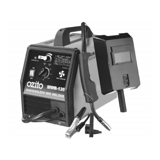
MIG WELDER
120 Amp
Gas/Gasless
Instruction Manual
3 Year Replacement Warranty
MWR-135
! !
WARNING! Read all safety warnings and all instructions. Failure to follow the
warnings and instructions may result in electric shock, fire and/or serious injury.
Save all warnings and instructions for future reference.
0312
www.ozito.com.au
To view the full range visit:
Advertisement
Table of Contents

Related Manuals for Ozito MWR-135


Summary of Contents for Ozito MWR-135
- Page 1 Gas/Gasless Instruction Manual 3 Year Replacement Warranty MWR-135 WARNING! Read all safety warnings and all instructions. Failure to follow the warnings and instructions may result in electric shock, fire and/or serious injury. Save all warnings and instructions for future reference.
-
Page 2: Specifications
SPECIFICATIONS - MODEL NO. MWR-135 Input: 230-240V ~ 50Hz Current Range: 40 - 120 Amp Duty Cycle: 60% @ 40 Amp, 8% @ 120 Amp Welding Wire Size: (0.6-0.8mm General Wire) (0.8-0.9mm Flux-Cored Wire) Insulation Type: Earthed Appliance (Class I) Welding wire spool weight: 0.2kg to 5kg... -
Page 3: Table Of Contents
TABLE OF CONTENTS SPECIFICATIONS…………………………………………… Page 1 KNOW YOUR PRODUCT………………………………….. Page 1 INTRODUCTION…………………………………………… Page 3 ELECTRICAL SAFETY………………………………………. Page 3 GENERAL SAFETY INSTRUCTIONS……………………… Page 4 ADDITIONAL SAFETY INSTRUCTIONS FOR WELDERS …… Page 5 ADDITIONAL SAFETY INSTRUCTIONS FOR MIG WELDERS…………………………………………………… Page 6 ASSEMBLY…………………………………………………… Page 7 OPERATION…………………………………………………... -
Page 4: Introduction
The electric motor has been designed for 230V and 240V only. Always check that the power supply corresponds to the voltage on the rating plate. Note: The supply of 230V and 240V on Ozito tools are interchangeable for Australia and New Zealand. -
Page 5: General Safety Instructions
GENERAL POWER TOOL SAFETY WARNINGS WARNING! Read all instructions. Failure to follow all instructions listed below may result in electric shock, fire and/or serious injury. The term "power tool" in all of the warnings listed below refers to your mains- operated (corded) power tool or battery-operated (cordless) power tool. -
Page 6: Additional Safety Instructions For Welders
GENERAL POWER TOOL SAFETY WARNINGS 13. Do not abuse the cord. Never carry the equipment by its cord or pull it to disconnect from the socket. Keep the cord away from heat, oil and sharp edges. 14. Store equipment. When not in use, equipment should be stored in a dry, locked up or high place, out of reach of children. -
Page 7: Additional Safety Instructions For Mig Welders
ADDITIONAL SAFETY INSTRUCTIONS FOR MIG WELDERS This appliance is not intended for use by persons (including children) with reduced physical, sensory or mental capabilities, or lack of experience and knowledge, unless they have been given supervision or instruction concerning use of the appliance by a person responsible for their safety. -
Page 8: Assembly
ASSEMBLY Setting the Welding Current in Gasless Welding Wire Mode When welding in the gasless mode, the welding current must be set as follows: To view the polarity terminal knobs, open the side cover (6) of the welder by raising the side cover release lever (8), lift the side cover (6) to view the polarity terminal knobs (Fig. - Page 9 Note: The adaptor, disposable argon cylinder, regulator and hose are available form your local gas supplier. The MWR-135 MIG welder is supplied with a 0.2kg coil of 0.8mm gasless welding wire (b) (Fig. 7). Welding wire up to 5.0kg can be fitted to this MIG welder using the 5.5kg...
- Page 10 ASSEMBLY (cont.) Fitting the Welding Wire 0.2kg coil (Fig. 8) Remove the wing nut (d) by rotating anti-clockwise and Drive washer (c) remove the drive washer (c) from the welding wire drive shaft (a). Drive Slide the 0.2kg coil onto the shaft (a) wire drive shaft (a).
- Page 11 ASSEMBLY (cont.) Wire Drive Roller Size Caution: It is critical that you choose the right wire drive roller (I) size (Fig. 9). There are two different size rollers included with the Gas/Gasless MIG welder, a roller to suit gasless flux-cored welding wire (0.8mm and 0.9mm) and general purpose wire (0.6mm and 0.8mm).
- Page 12 ASSEMBLY (cont.) Setting the Wire Drive Roller Size Release the pressure of the pressure roller (B) by loosening the adjustable pressure screw (C) anti-clockwise (Fig. 10). Push the pressure arm (D) down towards the base of the welder and swing the arm away form the welder (Fig.
- Page 13 ASSEMBLY (cont.) Adjusting the Drive Roller Pressure The pressure roller (B) applies pressure to the drive roller (I) through an adjustable pressure screw (C) and pressure arm (D). It is recommended that you adjust the adjustable pressure screw (C) in order to apply sufficient pressure to the wire drive roller (I), this will provide satisfactory wire feed and prevent the wire from slipping in the wire groove of the wire drive roller (I).
- Page 14 ASSEMBLY (cont.) Feeding the Welding Wire (Fig. 19) Adjustable pressure screw Pressure Roller Pressure Flexible inner tube Inlet guide Wire drive roller bracket Wire drive roller Fig. 19 1. Remove the shroud (11) and then unscrew the torch tip (12) from the MIG torch (10) by turning the torch tip (12) anti-clockwise.
-
Page 15: Operation
ASSEMBLY (cont.) Feeding the Welding Wire through to the MIG Torch (Fig. 21) Ensure the MIG torch (10) lead is straight, and the welder On/off switch (1) is turned on (Fig. 19). Feed the welding wire through to the MIG torch (10) by depressing the MIG torch (10) trigger switch. - Page 16 OERATION (cont.) Switching the Welder On and Off (Fig. 24) The On/Off Switch (1) will illuminate when the ON/OFF switch (1) is in the ON position. To turn the welder on, select the ON position. To turn the welder off, select the OFF position. Fig.
-
Page 17: Maintenance
This may result in arcing between the parts and their eventual failure. Note: Ozito Industries will not be responsible for any damage or injuries caused by the repair of the tool by an unauthorised person or by mishandling of the tool. -
Page 18: Spare Parts
SPARE PARTS Please contact your local Bunnings Special Orders Desk to order the required spare parts. Most common spare parts listed below Spare Part Part No. Welding torch assembly SPMWR135-04 On/off switch SPMWR135-12 Wire drive roller 0.6-0.8mm SPMWR135-56 Pressure roller SPMWR135-59 Wire drive roller 0.8-.09mm SPMWR135-92... -
Page 19: Pack Contents
Please recycle packaging where facilities exist. Check with your local council authority for recycling advice. PACK CONTENTS 1 x Gas/Gasless MIG Welder MWR-135 1 x Welding mask 1 x Combination chipping hammer and wire brush 1 x 0.6mm-0.8mm Wire feed roller (fitted to the welder) 1 x 0.8mm-0.9mm Wire feed roller... -
Page 20: Warranty
If the tool shows signs of damage or defects caused by or resulting from abuse, accidents or alterations. • Failure to perform maintenance as set out within the instruction manual. • If the tool is disassembled or tampered with in any way. OZITO Australia/New Zealand (Head Office) 1-23 Letcon Drive, Bangholme, Victoria, Australia 3175...
Need help?
Do you have a question about the MWR-135 and is the answer not in the manual?
Questions and answers