
Related Manuals for Hatz 2-4L41C


Summary of Contents for Hatz 2-4L41C
- Page 1 INSTRUCTION BOOK 2 - 4 L 41 C 2 - 4 M 41. 4 L 42 C 4 M 42 433 402 07 - ENG - 06.08 - 2 Printed in Germany...
- Page 2 HATZ spare parts and HATZ tools. The world-wide HATZ service network is also available to you for consultation and spare parts supply. For the address of your nearest HATZ service station, please refer to the attached list or the internet under: www.hatz-diesel.com The installation of inappropriate spare parts may cause problems.
-
Page 3: Table Of Contents
Contents Page Page Important notes on safe operation 5.3. Maintenance every 250 of the engine hours of operation 5.3.1. Engine oil change Description of engine 5.3.2. Cleaning cooling fan, cooling fins and oil cooler General information 5.3.3. Checking threaded connections 3.1. -
Page 4: Important Notes On Safe Operation Of The Engine
– Rotating parts must be shielded so that they cannot be touched accidentally when the engine is in- stalled in other equipment or machinery. Guards are available from HATZ to protect belt drives for cooling fans and generators. – Before attempting to start the engine it is essential to have studied the starting information in the Instruction Book. - Page 5 – Please pay attention to all advice- and warning stickers placed on the engine and keep them in legi- ble condition. Contact your next HATZ service station, if a sticker comes off or is illegible and ask for a new one.
-
Page 6: Description Of Engine
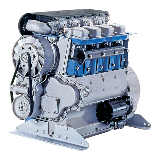
Description of engine Fully encapsulated „Silent Pack“ version Engine 2 ... 4 L 41 C 1 Access cover for fuel delivery pump 12 Air outlet duct 2 Oil filler pipe and dipstick 13 Capsule hood 3 Type plate 14 Suspension lug (retractable), 4 Speed control lever max. - Page 7 Description of engine Fully encapsulated „Silent Pack“ version Engine 4 L 42 C 1 Electronic control unit 14 Suspension lug (retractable), 2 Oil filler pipe and dipstick max. load 5000 N 3 Type plate 15 Air intake duct for capsule 4 Speed control lever 16 Combustion air intake aperture 5 Replaceable-element oil filter...
- Page 8 Description of engine Standard version Engine 2 ... 4 M 41 • 2 ... 4 M 41 Z 1 Oil filler pipe and dipstick 13 Cylinder head cover 2 Side panel 14 Air cleaner cover 3 Combustion air intake aperture 15 Suspension lug, max.
- Page 9 Description of engine Standard version Engine 4 M 42 1 Oil filler pipe and dipstick 14 Air cleaner cover 2 Side panel 15 Suspension lug, max. load 5000 N 3 Combustion air intake aperture 16 Fuel return line 4 Cooling fan drive belt 17 Fuel feed line with fuel pre-filter and 5 Cooling fan with alternator attached manual fuel pump...
-
Page 10: General Information
General information 3.1. Technical data 2 L 41 C 3 L 41 C 4 L 41 C / 4 L 42 C 2 M 41. 3 M 41. 4 M 41. / 4 M 42. Type Air-cooled, four-stroke diesel engine Combustion method Direct fuel injection Number of cylinders... -
Page 11: Transport
You can obtain a copy of this manual from your nearest HATZ service station. The type plate is placed on the crankcase resp. -
Page 12: Operation
Engine oil quantities and dipstick markings Operation dipstick 4.1. Before first start-up Oil content marking Engine type Sump (liter) (Figure 7, Engines are normally delivered without any fuel item 2) or oil. 2 L 41 C, 2 M 41 Z Yes 4.1.1. -
Page 13: Fuel
The engine should be in a horizontal position 4.1.2. Fuel before adding oil or checking the oil level. Stop the engine before refilling the fuel tank. Never refuel near a naked flame or sparks which could start a fire. Don’t smoke. -
Page 14: Starting The Engine
Models with manual fuel pump Low temperature resistance (On 4L42C and 4M42 engines only) At low temperatures, the viscosity of Diesel fuel increases. This may result in clogging of the fuel system. Thus, winter fuel must be used at out- side temperatures below 0 °C, or petroleum must be added in time. -
Page 15: Starting With The Electric Starter
If possible, disengage the engine from any driven equipment. The auxiliary equipment should always be placed in neutral. 4.2.1. Starting with the electric starter – Battery charge telltale „2“ and oil pressure warning „3“ must light up. – Turn start key to position II (Fig. 14). –... - Page 16 The preheating light „6“ lights up additionally at For troubleshooting regarding other flashing temperatures below 0° Celsius (Fig. 15). codes, please contact immediately your nearest HATZ service station. – After the light has gone out, start the engine Problems in the exhaust gas recirculation without delay.
-
Page 17: Emergency Starting
(see Chapter 7). If any problems arise, please contact the nearest Proceed as follows: HATZ service point. – Detach the hood of enclosure „13“ (Figures 1 and 2) or side panel „2“ (Figures 3 and 4). 4.2.3. Starting with handle... - Page 18 Important ! 3M41 three-cylinder engines Turn decompression levers only in the direction shown by the arrow. Exception: the lever can be moved back directly from posi- tion „1“ to „0“. Never operate the automatic decom- pression system when the engine is running.
-
Page 19: Starting With The Handle With Kick-Back Damping
– If the engine backfires during starting because it was not turned over with sufficient force (the engine could even start to run backwards in certain circumstances), release the starting handle immediately and move the speed con- trol lever to the STOP position (Chapt. 4.3.). The starting handle could be driven round by the engine and cause injury. -
Page 20: Stopping The Engine
– To repeat the starting attempt, wait for the en- gine to cease rotating, reset the automatic de- compression device and turn the starting handle in the correct starting direction again. 4.3. Stopping the engine If the engine is shut down for a short period, or at the end of the working day or shift, keep the key and the starting handel in a safe place, out of reach of un-... -
Page 21: Maintenance
Maintenance The engine must be stopped before any maintenance work is attempted. Comply with legal requirements when handling and disposing of old oil, filters and cleaning materials. Keep the engine’s starting key out of reach of unauthorized persons. Disconnect the negative battery terminal. At the end of the maintenance work, check that all tools have been removed from the engine and all safety guards, covers etc. - Page 22 2 M 41 without oil pan 2 M 41 with oil pan; 3 - 4 M 41 and 4 M 42 in all cases...
- Page 23 Depending on engine type and version, one of The following work is essential on new or the three self-adhesive maintenance charts illus- reconditioned engines after the first 25 hours trated here and on the previous page will be of operation: supplied.
-
Page 24: Maintenance Every
8 – 15 Maintenance every hours of operation 5.2.1. Check engine oil level When checking the oil level, the engine should be standing level, and must not be running. L3/63 1327/2 L3/47 – Check oil level at the dipstick. Add oil up to the MAX mark on dipstick „1“... - Page 25 On 2-4L41 C and 2-4M41 engines On 4L42 C and 4M42 engines – Increase the engine speed briefly to maximum level and watch out for the pilot lamp „5“ to flash. The following flashing code indicates that maintenance work is required on the air cleaner (Chapter 5.4.2).
-
Page 26: Check The Cooling Air System
5.2.3. Check the cooling air system 5.3. Maintenance every hours of operation Severe contamination with dirt is a sign that the air contains a high level of dust, and that the 5.3.1. Engine oil change maintenance intervals should be shortened (see Chapter 5.1.) accordingly. -
Page 27: Cleaning Cooling Fan, Cooling Fins And Oil Cooler
5.3.2. Cleaning cooling fan, cooling fins and oil cooler Before cleaning, the engine must be stopped and allowed to cool down. – On encapsulated engines, unscrew and remove the hood, side panel with speed control lever, cover plate on operating side and air outlet duct and cover plate on air outlet side (see Chapter 2). - Page 28 – Dry the engine with a compressed air jet. – Trace the cause of any contamination with oil and have the leak eliminated by a HATZ service station. – Install the capsule or air guide elements previously removed.
-
Page 29: Checking Threaded Connections
5.3.3. Checking threaded connections 5.3.4. Cleaning of mesh insert in exhaust pipe (additional equipment) Check the tightness of all threaded connections and take up slack if necessary, provided that Exhaust system components will natu- these can be reached during maintenance work. rally be hot and must not be touched while the engine is running or until it has Note:... -
Page 30: Check Water Trap
5.3.5. Check water trap 5.4. Maintenance every hours On 4L42C and 4M42 engines only) of operation The water trap inspection interval depends 5.4.1. Replace fuel pre-filter exclusively on the water contained in the fuel Do not smoke and never bring a naked and on the care applied in refuelling. -
Page 31: Air Cleaner Maintenance
Important ! 5.4.2. Air cleaner maintenance When installing a new filter, note the arrow indi- It is best to clean the filter cartridge(two pcs. on cating the correct flow direction (depends on four-cylinder engines) only when the mainte- whether the tank is mounted HIGH or LOW. nance indicator displays the appropriate signal. - Page 32 – Release clips „1“ and take off the cover of air cleaner housing „2“ (Figure 46). – Remove dirt adhering in the air cleaner area. – Slacken off screws „3“ only sufficiently to enable cover „4“ with the filter element to be lifted off.
- Page 33 Important Mechanical contamination indicator Air pressure must not exceed 5 bar, and the compressed air jet must be held approx. 150 mm (6 in) away from the filter cartridge. Damp or oily contamination – Renew the filter cartridge Checking the air filter cartridge L3/78 After the air cleaner has been re-assembled, the red zone „1“...
-
Page 34: Checking And Adjusting Valve Clearances
5.4.3. Checking and adjusting Adjusting method for two-cylinder engines valve clearances – On the encapsulated engine, take off the capsule hood (see Chapter 2). – Unscrew the hex nuts and take off the cylinder head cover (Figure 3, Item 13). –... -
Page 35: Engine Oil Change
– Check valve clearances with a feeler gauge. 5.4.4. Engine oil change – Valve clearances (inlet and exhaust valves) (see Chapters 5.3.1. and 5.1.) = 0.10 mm with engine cold. 5.4.5. Renewing oil filter Risk of scalding from hot oil. Trap the old oil and dispose of it in an environmentally acceptable manner. -
Page 36: Maintenance Every 1000 Hours Of Operation
1000 – Install the filter element and screw up 5.5. Maintenance every hours handtight. of operation – Open the fuel supply line again. 5.5.1. Renewing the fuel filter Do not smoke and never bring a naked flame near the fuel system when work- ing on it. - Page 37 Renewing the fuel filter (On 4L42C and 4M42 engines) – Release the fuel filter using a strap wrench or a similar tool, and remove it. – Close the fuel lines at the filter housing. – Slightly grease the seal „1“ of the new replace- –...
-
Page 38: Operating Checks And Repair Work
Operating checks and repair work 6.1. Checking operation of air cleaner maintenance indicator Every 250 hours of operation, perform a routine check on the maintenance indicator or mainte- nance switch and the display light. – Detach the capsule hood or side trim (see Chapter 2). -
Page 39: Renewing Fan Drive Belt, Checking Operation Of Belt Monitor
Mechanical maintenance indicator 6.2. Renewing fan drive belt, checking – Pull hose „2“ off air intake pipe and build up a operation of belt monitor strong vacuum at the open end (Figure 61). L3/249 L3/78 – Remove one machine screw at belt pulley „1“. –... - Page 40 – Push piston with tensioning pulley „2“ into housing „3“ and lock with the machine screw (Figure 66). L3/65 – Remove the machine screw to release the pis- ton with tensioning pulley „1“. L3/68 – Spring pressure will force the piston with ten- sioning pulley out of the housing.
- Page 41 Types of belt Since the belt pulleys on the fan side differ in diameter on various engine types and versions, Poly-V belts of differing lengths are fitted. Type Belt Fan pulley and engine Ident. No. length diameter version (mm) (mm) 2 L 41 C 502 031 00 All other types...
-
Page 42: Malfunctions - Causes And Remedies
Malfunctions – causes and remedies Kind of trouble Possibly caused by Remedy Chapt. Engine will not Speed control lever is in stop or Move lever to 1/2 START or start or is reluctant idle position. max. START position according to start although it to operating conditions. - Page 43 Kind of trouble Possibly caused by Remedy Chapt. At low Pre-heat system (optional extra) temperatures. has a fault. See workshop manual. Fuel has separated (inadequate Pull off fuel return line and low-temperature resistance). check that clear (not turbid) fuel emerges. 4.1.2.
- Page 44 Kind of trouble Possibly caused by Remedy Chapt. Engine fires but Stop signal from monitoring does not run after element for automatic shutdown the starter motor system (optional extra): is switched off. - oil pressure lost Check oil level. 5.2.1. - air cleaner blocked.
- Page 45 Kind of trouble Possibly caused by Remedy Chapt. Engine power and Air cleaner is blocked. Check degree of air cleaner speed drop, black contamination and renew filter smoke from ex- element if necessary. 5.4.2 haust. Valve clearances incorrect. Adjust valve clearances. 5.4.3.
-
Page 46: Work On The Electrical System
HATZ assumes no liability for electrical systems Do not place any tools on top of the battery. which have not been carried out acc. to HATZ circuit diagrams. Always disconnect the negative (–) terminal of the battery before working on the electrical system. - Page 47 CALIFORNIA Proposition 65 Warning Diesel engine exhaust and some of its constituents are known to the State of California to cause cancer, birth defects, and other reproductive harm.
Need help?
Do you have a question about the 2-4L41C and is the answer not in the manual?
Questions and answers