Table of Contents
Advertisement
Quick Links
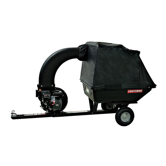
Operator's Manual
YARD VAC
Model No. 486.25012
IMPORTANT! The engine is shipped without oil. Oil must be added
before starting the engine. See Engine Maintenance on page 20 of
this manual for instructions.
CAUTION:
Before using this product, read
this manual and follow all Safety
Rules and Operating Instructions.
Sears, Roebuck and Co., Hoffman Estates, IL 60179 U.S.A.
www.sears.com/craftsman
PRINTED IN U.S.A.
®
STOP
DO NOT RETURN TO STORE
For Missing Parts or Assembly
Questions Call 1-866-576-8388
• Safety
• Assembly
• Operation
• Maintenance
• Parts
FORM NO. 42482 (05/09/12)
Advertisement
Table of Contents

Related Manuals for Craftsman 486.25012


Summary of Contents for Craftsman 486.25012
- Page 1 DO NOT RETURN TO STORE YARD VAC For Missing Parts or Assembly Questions Call 1-866-576-8388 Model No. 486.25012 IMPORTANT! The engine is shipped without oil. Oil must be added before starting the engine. See Engine Maintenance on page 20 of this manual for instructions.
-
Page 2: Table Of Contents
PARTS ORDERING/SERVICE ...... BACK PAGE ASSEMBLY ..............9 WARRANTY CRAFTSMAN FULL WARRANTY FOR ONE YEAR from the date of purchase, this product is warranted against defects in material or workmanship. A defective product will receive free in-home repair or replacement if repair is unavailable. -
Page 3: Safety
SAFETY Any power equipment can cause injury if operated improperly or if the user does not understand how to operate the equipment. Exercise caution at all times when using power equipment. • • If the cutting mechanism strikes a foreign object, or if your Read and follow all instructions in this manual before attempting to assemble or operate this equipment. Failure Yard Vac should start to vibrate abnormally, stop the engine to comply with these instructions may result in personal immediately, disconnect spark plug wire and move the wire injury. Keep this manual in a safe place for future reference away from the spark plug. - Page 4 WARNING TO AVOID SERIOUS INJURY • Read Owner’s Manual and all safety labels on machine before starting and using machine. • Do Not remove top cover or attempt to empty contents of cart while engine is running. • Do Not stand behind cart in exhaust discharge area while engine is running. • Keep hands, feet, face, long hair and clothing out of chipper inlet, vac inlet, and discharge area.
-
Page 5: Accessories And Attachments
ACCESSORIES AND ATTACHMENTS These accessories were available when the unit was purchased. They are also available at most Sears retail outlets and service centers. Most Sears stores can order repair parts for you when you provide the model numbers of your tractor and Yard Vac System. -
Page 6: Full Size Hardware Chart (Cart)
FULL SIZE HARDWARE CHART (CART) NOT SHOWN FULL SIZE REF. PART NO. QTY. DESCRIPTION REF. PART NO. QTY. DESCRIPTION Hex Bolt, 5/16-18 x 4" 47407 HA21362 Nylock Nut, 3/8-16 Hex Bolt, 3/8-16 x 3" 712-3083 Nylock Nut, 1/2-13 43574 Hex Bolt, 1/2-13 x 1-1/4" 1543-69 Nylon Washer 43351 Hex Bolt, 1/4-20 x 1-1/4" Washer, 1/4" Std. 43088 1509-90 Hex Bolt, 3/8-16 x 1"... -
Page 7: Full Size Hardware Chart (Adapter)
FULL SIZE HARDWARE CHART (ADAPTER) NOT SHOWN FULL SIZE REF. PART NO. QTY. DESCRIPTION REF. PART NO. QTY. DESCRIPTION Washer, 5/16" Std. Hex Bolt, 1/4-20 x 1-1/4" 43081 1509-90 Hex Bolt, 5/16-18 x 1-1/4" 1543-69 Nylon Washer 43840 Hex Bolt, 1/4-20 x 1" 44850 Tarp Strap 43661 Carriage Bolt, 5/16" x 3/4" 43080 23826 Angle Bracket "S" Hook Washer, 1/4" Std. 43088 44849 47810... -
Page 8: Carton Contents
CARTON CONTENTS REF. PART NO. QTY. DESCRIPTION REF. PART NO. QTY. DESCRIPTION 48791 Cart Tray 24497 Latch Stand Bracket 40343 Cart Cover 49873 Lower Support Rod Tarp Strap, 25" 41310 Engine 43790 43791 Hose Adapter 49974 Hose Hanger Rod Rope, 36" 65518 24386 Latch Stand Plate 25742 Front Tongue... -
Page 9: Assembly
ASSEMBLY • This unit is shipped WITHOUT GASOLINE or OIL. After Attach the hitch bracket to the front tongue using two 3/8" x 1" bolts and 3/8" nylock nuts. See figure 2. assembly, see separate engine manual for proper fuel and engine oil recommendations. • Assemble the front tongue on top of the rear tongue using three 3/8" x 3" hex bolts and 3/8" nylock nuts. - Page 10 • Assemble an axle clip, a wheel and a 5/8" washer onto • Place the cart bed braces and the cart tray onto each end of the axle. Assemble a second 5/8" washer the wheel support. Secure latch stand bracket onto each end of the axle if space allows. Secure both underneath the tongue's latch lock lever. See figure 6. wheels in place using two cotter pins. See figure 4. • Assemble the cart tray and cart bed braces to the wheel support using eight 5/16" x 3/4" hex bolts and WHEEL 5/16" nylock nuts. Tighten nuts after all bolts are in AXLE place. See figure 6. 5/8"...
- Page 11 • • Attach the engine mounting plate to the tongues Place the hose hanger rod down into the hose hanger using two 3/8" x 3" hex bolts in the back holes, two bracket on the impeller housing assembly. See figure 3/8" x 1" hex bolts in the front holes and four 3/8" nylock nuts. See figure 7. HINT: For easier assembly, support the rear tongue with a block of wood. HOSE HANGER 3/8" x 1" HEX BOLT 3/8"...
- Page 12 • Loop the 25" tarp strap under the hose. Fasten the CART COVER ASSEMBLY hooks to the hose hanger rod. See figure 11. • Slide the front support tube through the double loops at the front of the cart cover. See figure 13. HOSE HANGER ROD DOUBLE LOOPS 25" TARP STRAP FRONT FIGURE 11 SUPPORT TUBE CART COVER FIGURE 13 • Slide the front support rod (straight ends) through the front sleeve located in the top of the cart cover.
- Page 13 • • Slide the second lower support rod (bent ends) Place the top support angle inside the cart cover. through the sleeve along the bottom of the cart cover. Fold the bottom of the cover around the top support angle. Insert two plastic plugs as shown in figure 17 Slide a looped end of the rope onto the rod as it enters each gap in the sleeve.
- Page 14 • • Assemble a 1/4" x 3/4" bolt and 1/4" lock nut to each Secure front support tube to top support angle using two 1/4" x 1-1/4" hex bolts and 1/4" lock nuts. end of the second lower support rod. TIGHTEN, then back nut off 1/2 turn. See figure 21. TIGHTEN. Do not over tighten and collapse support tube. See figure 19. • Attach the lower support rod to the outside of the top support angle using two 1/4" flanged nuts. TIGHTEN.
- Page 15 • • Place the assembled cart cover on top of the cart, With the rope hanging down loosely, check if the cover fits down freely around the rear of the cart tray. aligning the bolts in the top support angle with the holes in the cart. Assemble five 1/4" flanged nuts onto If the cover needs to extend farther to the rear, loosen bolts (a) in figure 24 to slide the support rod rearward. the bolts. DO NOT TIGHTEN YET. See figure 23. •...
- Page 16 BEFORE PROCEEDING, look in the fold-out sheets included with this manual STOP to find templates for Sears mower decks. If written instructions are printed on the template, follow those instructions instead of the instructions in this manual. • Position the adapter over the deck opening, and check ASSEMBLING THE #62468 DECK ADAPTER for fit of cutout as shown in figure 27. Trim cutout, if TO THE MOWER DECK necessary, to allow tilting of adapter, keeping the fit as...
- Page 17 • • Assemble the adapter bracket to the deck using two With deck adapter positioned correctly over the 5/16" x 1-1/4" hex bolts, 5/16" flat washers and 5/16" discharge opening, use the adapter bracket as a nylock nuts. See figure 29. template and drill three 9/32" diameter holes in the top of the deck adapter. See figure 30. NOTE: It may be necessary to use extra 5/16" flat washers to shim under the bracket next to the deck • Bolt deck adapter to bracket using three 1/4" x 1" surface. Ten extra washers have been furnished as bolts, nylon washers, 1/4" flat washers and 1/4" shims. See figure 29. nylock nuts. Nylon washers should be against the inside of the deck adapter. See figure 30.
-
Page 18: Operation
OPERATION KNOW YOUR VAC SYSTEM Read this owner's manual and safety rules before operating your Vac System. Compare the illustration below with your Vac System to familiarize yourself with the various controls and their locations. BOOT THROTTLE CONTROL CHOKE CONTROL FUEL SHUT-OFF ON/OFF SWITCH LATCH LOCK LEVER THROTTLE CONTROL Controls speed of engine. BOOT Connects the plastic elbow to the fabric top, CHOKE CONTROL Adjust to allow cold starting. - Page 19 HOW TO START YOUR VAC SYSTEM HOW TO USE YOUR VAC SYSTEM CAUTION: Vehicle braking and stability WARNING: Never start or run the engine may be affected with the addition of an without all covers being properly attached to accessory or an attachment. Be aware of the blower housing and cart.
-
Page 20: Maintenance
MAINTENANCE CUSTOMER RESPONSIBILITIES • Read and follow the maintenance schedule and the maintenance procedures listed in this section. MAINTENANCE SCHEDULE Fill in dates as you Service Dates complete regular service. Check for loose fasteners Check cover Check tire pressure Check engine oil level Lubricate Clean Maintain engine per instructions below and in engine manual. -
Page 21: Storage And Optional Use
STORAGE AND OPTIONAL USE • Clean the engine and the entire unit thoroughly. TO USE THE CART WITHOUT THE VAC SYSTEM • • Refer to engine manual for correct engine storage Remove bolts holding frame to cart and store bag instructions. -
Page 22: Repair Parts
REPAIR PARTS LIST FOR 486.25012 VAC... - Page 23 REPAIR PARTS LIST FOR 486.25012 VAC REF. PART NO. QTY. DESCRIPTION REF. PART NO. QTY. DESCRIPTION 48791 Cart Tray 47189 Nylock Nut, 1/4-20 Rope, 36" 65518 47810 Nylock Nut, 5/16-18 Hex Bolt, 1/4-20 x 3/4" Washer, 5/8" 43012 R19212016 24386 Latch Stand Plate 43010 Cotter Pin Hex Bolt, 5/16-18 x 3/4"...
- Page 24 REPAIR PARTS FOR MODEL 486.25012 VAC See page 26 ADAPTER #62468...
- Page 25 REPAIR PARTS FOR MODEL 486.25012 VAC REF. PART NO. QTY. DESCRIPTION REF. PART NO. QTY. DESCRIPTION Hex Bolt, 3/8-16 x 3" 27144 Top Support Angle 43574 Washer, 1/4" Std. 25874 Front Support Tube 43088 25876 Brace 1543-69 Nylon Washer Washer, 5/16" Std. 49873 Lower Support Rod 43081 Hex Bolt, 5/16-18 x 1-1/4"...
- Page 26 REPAIR PARTS LIST FOR 486.25012 VAC REF. PART QTY. DESCRIPTION REF. PART QTY. DESCRIPTION 629-0241A Harness, Wire 725-1700 Switch Cover 24634 Housing Assembly, Inner 725-3166 Snap Mount Switch 726-0272 Clamp 24633 Housing Assembly, Outer Hex Bolt, 5/16-18 x 3/4" 43182 731-1613 Switch Cover Hex Bolt, 5/16-24 x 1"...
- Page 27 SUGGESTED GUIDE FOR SIGHTING SLOPES FOR SAFE OPERATION OF TRACTOR WITH ATTACHMENT ONLY RIDE UP AND DOWN HILL, NOT ACROSS HILL 10 DEGREES MAX. WARNING: To avoid serious injury, operate your tractor up and down the face of slopes, never across the face. Do not operate on slopes greater than 10 degrees.
-
Page 28: Parts Ordering/Service
1-800-659-5917 Craftsman Help Line www.craftsman.com ® Registered Trademark / Trademark of KCD IP, LLC in the United States, or Sears Brands, LLC in other countries ®...