Table of Contents
Advertisement
TM
20 00
W
SI NE
W AV
FR EE
E IN
DO
VE
M
RT ER
SW
/C HA
20 00
RG
ER
Mo
Nu
del
mb
er
FG
FS W
Nu
A
mb
er
20 00
81 5-
20 00
In ve
rt er
No
No
m in
M od
m in
al DC
e:
No
al AC
Op
m in
er at
M ax
al AC
Ou
in g
M ax
. Co
tp ut
Vo
. Op
nt in
Ou
tp ut
Vo
lta
M ax
uo
lta
ge
. Co
er at
us
Fr eq
ge
: 12
: 12
In pu
nt in
in g
AC
ue nc
0 Va
Vd c
M ax
t: 20
uo
DC
Ou
tp ut
y: 60
M ax
. Ou
us
In pu
c
tp ut
00
W at
AC
t Cu
Cu
rre
Hz
, 1Ø
M ax
. DC
Ou
tp ut
rre
nt :
. Am
In pu
Su rg
30 °C
nt :
16 .66
t Vo
e Po
at
25 2
Ch
bi en
lta
w er
No
m in
A
A
ar ge
t Te
ge
(1 0
No
r M
m pe
: 15
al DC
m in
od
ra tu
.5 Vd
s du
Po
w er
al AC
e:
re :
c
ra tio
Ch
50 °C
n) :
ar gi
Fa ct
In pu
40 00
M ax
ng
or :
t Vo
. Co
DC
> 0.9
lta
VA
No
nt in
Ou
5
ge
M ax
m in
uo
tp ut
: 12
. AC
al AC
us
Vo
0 Va
In pu
Ba
tte
lta
c
In pu
ry
ge
, 60
IN S
t Cu
t: 10
Ch
Ra
ng
Hz ,
T A
rre
0 A
ar ge
e: 11
1Ø
M ou
LL A
nt
(ch
r DC
.0 -
sp ec
nt
ar ge
Cu
16 .0
ifi ed
th is
T IO
rre
C A
in ve
N R
+ pa
nt
Vd c
U T
in th
rte
ss -th
at
UL
CSA
458
co ve
IO N
e in
r/c ha
E Q
ro ug
303
361
107
r or
sta
rg er
U IR
4
.1-0
1
in a
ob str
:
lla tio
on ly
E M
h) :
re su
ze ro
To
n gu
48
lt.
-cl ea
uc t
re du
id e
in th
E N
A rm
W A
Do
ra nc
ve nt
ce
pr ov
e or
T S :
s
no t
e co
ila tio
th e
ien
us er
R N
ex po
n op
ris k
id ed
ta tio
IN G
m pa
of
.
ns
DC
se rv
se
to
rtm
en in
fir e,
Us e
so ur
ice
ab le
:
ra in
en t.
gs .
do
ce s.
Sh oc
or
Ov
Do
no t
sp ec
on ly
Di sc
pa rts
k ha
sp ra
er he
no t
ifi ed
gr ou
on ne
. En
za rd
y.
at in
m ou
ty pe
nd -fa
er gi
. Do
g m
nt
t
th is
s m
in th
ct all
ze d
ay
Fa ul
eq ui
ay
fa il
e in
ul t
cir cu
so ur
fro
no t
lea
d- ac
pm
to
sta
ce s
m bo
op en
ca us
en t.
op er
lla tio
it in
. No
in g
id ba
at e
n gu
te rru
be fo
th
AC
D A
tte
Re fe
pr op
id e
pt er
re se
an d
N G
pe rso
rie s.
r to
su pp
s (G
rv ici
tt
in sta
na l
Ot he
m an
er ly
lie d.
FC I)
ng .
Ba
E R
in ju
ua l.
wh
eu ip
ll in
:
ry an
r ba
en
Ot he
%
m en
an
To
d da
tte
ry ty
Ch
ar ge
co nn
r
t is
ar ea
re du
ec te
re qu
in wh
ce
m ag
pe s
on ly
d to
ire d.
ich
th e
e.
m ay
ig ni
ris k
bu rst
tio
of
n- pr
ex pl
ot ec
os io
te d
n, do
no t
Se ria
l Nu
mb
er
Da
te
of
Ma
nu
fac
tur
e
De
sig
As sem
ne d
ble
in Ca
d in
na da
Ch
ina
.
.
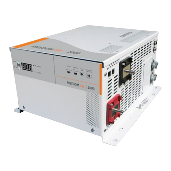
Freedom SW 2000
Sine Wave Inverter/Charger
Ba
nk
ry
h)
Fa ul
Ba
tte
y (A
pa
cit
t
Ca
arc
h
30
Se
de
00
0
Mo
10
10
Ty pe
Of
f
80
0
Ba
ry
60
0
20
0
tt
tte
Ma
x
40
0
%
Ba
od
ed
Inp
ut
AG
M/
Flo
AC
GE
L
rro
w
Na
de
Wi
kW
In ve
rt in
g
A
Ch
ar gi
ng
rt in
g
In ve
kW
ar gi
ng
Ch
A
AC
Inp
ut
Wi
de
Ba
tte
Na
ry
rro
w
AG
Ty pe
GE
M/
L
Se
Flo
arc
od
ed
Mo
h
Ma
de
x
Ba
tte
Ca
ry
f
Of
pa
cit
Ba
nk
y (A
10
00
h)
80
0
60
0
30
40
0
20
0
10
0
TM
Installation Guide
Advertisement
Table of Contents

Related Manuals for Xantrex Freedom SW 2000


Summary of Contents for Xantrex Freedom SW 2000
- Page 1 Se ria l Nu As sem ne d in Ca d in na da Installation Guide Freedom SW 2000 Sine Wave Inverter/Charger...
-
Page 3: Freedom Sw
Notice of Copyright Contact Information Freedom SW 2000 Sine Wave Inverter/Charger Installation Guide © May 2010 Xantrex Technology Inc. All rights reserved. No part of this document may be Telephone: 1 800 670 0707 (toll free North America) reproduced in any form or disclosed to third parties without the express written 1 408 987 6030 (direct) consent of: Xantrex Technology Inc., 161-G South Vasco Road, Livermore,... -
Page 4: About This Guide
Audience The guide is intended for qualified installers who need to install and configure the Freedom SW 2000 Inverter/Charger. The installer should have knowledge and experience in installing electrical STATEMENT OF HAZARD equipment, knowledge of the applicable installation codes, and awareness Contains statements of avoidance or strict compliance. - Page 5 IMPORTANT: These notes describe things which are important for you to know, however, they are not as serious as a caution or warning. Related Information You can find more information about Xantrex Technology Inc. as well as its products and services at www.xantrex.com. 975-0527-01-01...
-
Page 6: Important Safety Instructions
FUTURE REFERENCE ELECTRICAL SHOCK HAZARD • Do not expose the Freedom SW 2000 to rain, snow, spray, or bilge This chapter contains important safety and installation instructions for the water. This inverter/charger is designed for indoor use only. Freedom SW 2000 Inverter/Charger (Freedom SW 2000). Each time, •... - Page 7 NOTES: Follow these instructions and those published by the battery manufacturer and the manufacturer of any equipment you intend to use FIRE AND BURN HAZARD in the vicinity of the battery. Review cautionary markings on these Do not cover or obstruct the air intake vent openings and/or install in a products and on the engine.
-
Page 8: Precautions When Working With Batteries
Failure to follow these instructions can result in death or serious injury. NOTES: Locate the Freedom SW 2000 Inverter/Charger unit away from batteries in a well ventilated compartment. Always have someone within range of your voice or close enough to come to your aid when you work near a lead-acid battery. - Page 9 • Make sure the voltage of the batteries matches the output voltage of • Never place the Freedom SW 2000 Inverter/Charger unit directly the inverter/charger. above batteries; gases from a battery will corrode and damage the •...
- Page 10 Canadian standards. For more information see “Regulatory Approvals” on page 68 of the Owner’s Guide. The Freedom SW 2000 Inverter/Charger is intended to be used for RV, marine, and commercial truck applications. It is not intended for other applications as it may not comply with the additional safety code requirements needed for those other applications.
-
Page 11: Table Of Contents
Unpacking and Inspecting the Freedom SW 2000 Inverter/Charger ....... . . - Page 12 Installation Tools and Materials ..................13 Tools .
- Page 13 Inverter/Charger Physical Specifications..................36 Battery Information .
-
Page 15: Introduction
Introduction The Installation Guide provides detailed information for installing the Freedom SW 2000 Inverter/Charger and the battery temperature sensor and wiring the inverter/charger to the AC and DC circuits. This Installation Guide provides: • safety instructions that must be observed during installation, •... -
Page 16: Materials List
• two sets of nuts and washers for the DC terminals. Owner’s Guides NOTE: If any of the items are missing, contact Xantrex or any authorized Xantrex dealer for replacement. See “Contact Information” on page i. Freedom SW 2000 IMPORTANT: Keep the carton and packing material in case you need to return the Freedom SW 2000 for servicing. -
Page 17: Installation Information
Installation Information Before You Begin the Installation Installation Codes Before beginning your installation: Applicable installation codes vary depending on the specific location and application of the installation. Some examples are: • Read the entire Installation Guide so you can plan the installation from beginning to end. -
Page 18: Planning The Installation
Two key factors in particular will have a major impact on system As your system configuration is determined, record the details in performance. Information About Your System of the Freedom SW 2000 Sine Wave Inverter/Charger Owner’s Guide. Size and Length of DC Cables To select the appropriate size and length of DC cables, see “DC Cabling”... -
Page 19: Ac And Dc Components Including Wire And Breaker Sizes
Planning the Installation AC and DC Components including wire and breaker sizes Sine Wave Inverter/Charger For a successful installation, you need to plan for AC and DC components including planning for wire and breaker sizes to be used in the power system. - Page 20 HOT = BLACK NEUTRAL = WHITE 8 AWG Chassis GND GND = GREEN/Bare 4/0 AWG Neutral 250 A fuse** 12 volt Battery (Bank) ** Class T or equivalent Figure 3 Wiring and Breakers Block Diagram Freedom SW 2000 Installation Guide...
-
Page 21: Ac Components
AC Input AC Disconnect and Over-Current Protection Devices AC input to the Freedom SW 2000 can be supplied from a single-phase 120-volt 60-Hz AC source such as the utility grid (power company), a To meet CSA, UL, and electrical code requirements, and to protect system generator, or the output of a transfer switch. -
Page 22: Distribution Panels
AC Output Protection Tested GFCIs The breaker between the Freedom SW 2000 AC output and the AC loads Compliance with UL standards requires that Xantrex test and recommend must be rated to protect the AC output wire size used. If the AC output specific GFCIs for use on the output of the inverter. -
Page 23: Ac Wiring
All wiring must be rated 90 °C or higher. Bonding system The Freedom SW 2000 provides a system that automatically connects the neutral conductor of the inverter’s AC output Size of AC Input Wiring Wire size must be coordinated with the circuit to safety ground (“bonding”... -
Page 24: Dc Components
Batteries DC Disconnects and Over-Current Devices The Freedom SW 2000 system requires a 12 volt, lead-acid deep-cycle The DC circuit from the battery to the inverter/charger must be equipped battery or group of batteries to provide the DC current that the inverter/ with a disconnect and over-current protection device. -
Page 25: Dc Cabling
Size and Length See Table 3 for required DC cable length, cable size and required fuse size for the Freedom SW 2000. Wire size is usually marked on the cables. IMPORTANT: Using a smaller gauge cable or a longer cable may cause the inverter to shut down under heavy load. -
Page 26: Unpacking And Inspecting The Freedom Sw 2000 Inverter/Charger
Always use proper lifting techniques during installation to prevent personal injury. Record the serial number of the Freedom SW 2000 and other purchase information in the “Warranty and Product Information” section of the Failure to follow these instructions can result in minor or moderate Freedom SW 2000 Sine Wave Inverter/Charger Owner’s Guide. -
Page 27: Installation Tools And Materials
Planning the Installation Installation Tools and Materials Tools Materials You will need the following tools to install the Freedom SW 2000 and the You will need the following materials to complete your installation: battery temperature sensor. ❐ Strain-relief clamp(s) for AC cables (not provided): 1"... -
Page 28: Installing The Inverter/Charger
Step 3: Connecting the AC Input and AC Output Wires Step 4: Connecting the DC Cables Step 5: Connecting the Battery Temperature Sensor (BTS) Step 6: Performing Checks Prior to Initial Start-Up Step 7: Testing Your Installation Freedom SW 2000 Installation Guide... -
Page 29: Step 1: Choosing A Location For The Inverter/Charger
Clearance Allow as much space around the inverter/charger as injury. possible. Xantrex recommends that other objects and surfaces be at least 3 inches (76 mm) away The location of the inverter/charger is a key factor in system performance. from the ventilation openings for best performance. - Page 30 Orientation To meet regulatory requirements, the Freedom SW 2000 must be mounted in one of the approved mounting orientation. See Figure 1 on page 18. Freedom SW 2000 Installation Guide...
-
Page 31: Step 2: Mounting The Inverter/Charger
Considerations To mount the inverter/charger: Remove the inverter/charger from its shipping container. Before mounting the Freedom SW 2000, take the following two factors into Verify that all components are present, and record relevant product account. information on form WA-4 in the Freedom SW 2000 Sine Wave The weight of the inverter/charger requires two people to install it. - Page 32 Wall Mount DC on Left On a vertical surface with DC terminals facing left. IMPORTANT: This orientation is also suitable for marine applications only with the installation of additional drip protection. Freedom SW 2000 Installation Guide...
- Page 33 Installing the Inverter/Charger Approved Mounting Orientation Orientation? Comment Wall Mount DC on Right On a vertical surface with DC terminals facing right. IMPORTANT: This orientation is also suitable for marine applications only with the installation of additional drip protection. Wall Mount DC Up Not acceptable.
-
Page 34: Step 3: Connecting The Ac Input And Ac Output Wires
AC wiring box. Use the same trade size of strain relief as the trade size of the knockout(s) you are using. AC Wiring Terminals The AC wiring terminals accept cables of a specific size. See “AC Wiring” on page 9 for required sizes. Freedom SW 2000 Installation Guide... -
Page 35: Connecting Ac Input Wires
Installing the Inverter/Charger Connecting AC Input Wires Figure 2 shows the wiring compartment, which contains a grounding bus EQUIPMENT DAMAGE (used to wire the AC input and output ground wires) and a terminal block The terminal block is split into INPUT and OUTPUT sections. Damage (used to wire the AC input and AC output connections). -
Page 36: Connecting Ac Output Wires
Using a 1/4" blade slot screwdriver, loosen the terminal screws on the AC output terminals. Do not remove the screws. Connect the line and neutral wires to the output terminals (labeled AC Output on the terminal block, Figure 2 on page 21) as follows: Freedom SW 2000 Installation Guide... - Page 37 Installing the Inverter/Charger Table 4 Output AC Wire Size Wire Size No. 10 AWG L: black: Color Coding N: white G: green Tighten the terminal screws. Leave some slack wire inside the wiring box. Secure the strain-relief clamp on the AC output cable jacket. Attach the wiring compartment cover panel and tighten the four screws.
-
Page 38: Step 4: Connecting The Dc Cables
Xantrex recommends the use of crimp connectors. The connector should be designed for a 5/16" DC stud size on the Freedom SW 2000 inverter, while battery/fuse cable end may require a larger size such as 3/8"... -
Page 39: Guidelines For Routing The Dc Cables
Installing the Inverter/Charger Guidelines for Routing the DC Cables Follow these guidelines to ensure maximum performance. ELECTRICAL SHOCK AND FIRE HAZARD Route the cables away from sharp edges that might damage the insulation. Avoid sharp bends in the cable. Failure to follow these instructions will result in death or serious injury. -
Page 40: Connecting The Dc Cables To The Inverter/Charger
Make sure the bolts supplied by positive side of the DC circuit, as close as possible to the battery. Xantrex on the inverter/charger are tightened to a torque of 10–11 ft-lbs This protects your battery and wiring in case of accidental shorting. - Page 41 Installing the Inverter/Charger Figure 4 DC Terminal Covers Figure 3 DC Cable Connections Before proceeding, check that the cable polarity is correct: POSITIVE (+) on the inverter/charger is connected to the POSITIVE (+) on the battery, and NEGATIVE (–) cable is connected to the NEGATIVE (–) terminal on the inverter/charger.
-
Page 42: Dc Grounding
In an RV or vehicle installation, the DC grounding point will usually be the vehicle chassis or a dedicated chassis ground bus. Tighten the nut to a torque of 4.7–5.4 ft-lbs (6.6–7.3 Nm). Chassis ground point Figure 5 DC Wiring and DC Grounding Freedom SW 2000 Installation Guide... -
Page 43: Step 5: Connecting The Battery Temperature Sensor (Bts)
Installing the Inverter/Charger Step 5: Connecting the Battery Temperature Sensor (BTS) Installing a battery temperature sensor (BTS) extends the life of a battery by preventing overcharging in warm temperatures and undercharging in cold temperatures. With a BTS monitoring the battery temperature, the voltage Connector delivered to the battery is adjusted according to the battery’s actual temperature. -
Page 44: Mounting To The Negative Battery Terminal
Route the sensor cable to the inverter/charger and plug it into the BTS Switch off all devices operating from the battery, or open the battery jack, as shown in Figure 8. Secure the cable along its length. switch (if present) to disconnect the battery. Freedom SW 2000 Installation Guide... - Page 45 Installing the Inverter/Charger Inpu Inpu W ide N arro N arro tery tery M ode M ode O ff O ff C apa C apa y Ban y Ban c ity ty ( ( Ah) 200 0 Figure 8 Connecting the BTS Cable to BTS Jack 975-0527-01-01...
-
Page 46: Mounting To The Side Of The Battery Case
This surface must be in direct internal contact with the battery electrolyte. Do not install the sensor near the top of the battery or on the battery’s top surface. Freedom SW 2000 Installation Guide... -
Page 47: Step 6: Performing Checks Prior To Initial Start-Up
Installing the Inverter/Charger Step 6: Performing Checks Prior to Initial Start-Up Before testing your installation, ensure these conditions are met: ❐ Chassis and AC grounds are properly installed. ❐ AC input connections and AC output connections are wired correctly on the terminal block and not reversed. ❐... -
Page 48: Step 7: Testing Your Installation
• the Freedom SW 2000 works in AC pass-through mode. To test the Freedom SW 2000 in invert mode, using a 100 watt light If the test fails at any point, go to “Step 6: Performing Checks Prior to bulb as the test load: Initial Start-Up”... -
Page 49: Testing In Charge Mode
Charge Mode indicator light illuminating orange. It takes about Freedom SW 2000 Sine Wave Inverter/Charger Owner’s Guide. 15 seconds for the unit to transition from invert mode to charge mode after the application of qualified AC. -
Page 50: Inverter/Charger Physical Specifications
Inverter/Charger Physical Specifications For complete inverter/charger specifications, refer to the Freedom SW 2000 Sine Wave Inverter/Charger Owner’s Guide. The physical specifications of the Freedom SW 2000 are described in Table 5 below. Table 5 Freedom SW 2000 Physical Specifications Length 15.2 inches (385 mm) -
Page 51: Battery Information
Obtain the amp-hours that the appliance requires by dividing that continuous loads like an inverter. Deep-cycle batteries use a more suitable amount by 10 (the factor for the Freedom SW 2000, which is a 12-volt rating system such as amp-hours (Ah). - Page 52 This example illustrates how quickly your battery needs can escalate. To reduce the required battery bank size, you can either conserve energy by eliminating or reducing the use of some loads, or recharge more frequently. Freedom SW 2000 Installation Guide...
-
Page 53: Battery Banks
An appliance may require three to six times its normal running current in battery to obtain sufficient capacity. Batteries can be connected in parallel, order to start. The Freedom SW 2000 can handle surges to 4000 W for ten in series, or in series-parallel to create higher capacity systems. - Page 54 = Total watt-hours of AC load between charges Battery Ah used between charges (divide by 10 for 12 volt system; divide by 20 for 24 volt system) Recommended Battery Bank Size in Ah (multiply by 2) Freedom SW 2000 Installation Guide...
-
Page 55: Cabling And Hook-Up Configurations
Cabling and Hook-up Configurations Parallel Connection Several smaller batteries can be connected to create a battery bank of substantial size. You can connect batteries in three ways: in parallel, series, Batteries are connected in parallel when all the positive terminals of a group or series-parallel. -
Page 56: Series Connection
In a series configuration, the battery bank has the same Ah rating of a single battery, but an overall voltage equal to the sum of the individual batteries. See below. Figure 12 Batteries Connected in Series Freedom SW 2000 Installation Guide... -
Page 57: Series-Parallel Connections
Cabling and Hook-up Configurations Series-Parallel Connections As the name series-parallel implies, both the series and parallel configurations are used in combination. The result is an increase in both the voltage and the capacity of the total battery bank. This is common with all battery-inverter system voltages. - Page 60 Xantrex Technology Inc. 1 800 670 0707 Tel toll free 1 408 987 6030 Tel direct 1 800 994 7828 Fax toll free customerservice@xantrex.com www.xantrex.com 975-0527-01-01 Printed in China.
Need help?
Do you have a question about the Freedom SW 2000 and is the answer not in the manual?
Questions and answers