United States Stove Company King Owner's Manual
Hide thumbs
Also See for King:
- Owner’s instruction and operation manual (45 pages) ,
- Owner's manual (49 pages)
Table of Contents
Advertisement
S
C
U
S
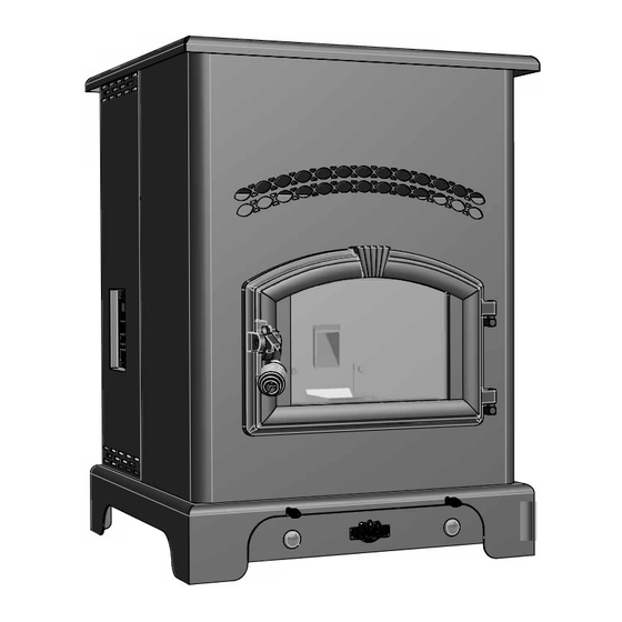
King Pellet Stove
4
4
Please read this entire manual before installation and use of this appliance. Failure to follow
these instructions could result in property damage, bodily injury, or even death.
Contact your local building or fire officials about restrictions and installation inspection
requirements in your area.
Save these instructions.
UNITED STATES STOVE COMPANY • 227 INDUSTRIAL PARK ROAD • SOUTH PITTSBURG, TENNESSEE 37380 • WWW.USSTOVE.COM
USSC
NorthlineExpress.com
UNITED STATES STOVE COMPANY
"Keeping North America Warm Since 1869"
Owner's Manual
FOR TECHNICAL ASSISTANCE:
http://www.northlineexpress.com
3
model 5510
TOLERANCES
EXCEPT
AS
NOTED
3
PHONE: (800) 750-2723
2
DESCRIPTION
HOLES
`
ASSEMBLY
.005"
DECIMAL
FINISH
.XX = 0.03 XXX = 0.010
ANGULAR
REFERENCE
`
~
5510
2
2
FAX: (423) 837-2109
Part No.: 851712
Toll-Free 1-866-667-8454
REV
A
SCALE
SIZE
REV
B
DWN BY
TITLE
DATE
K
A
1
Advertisement
Table of Contents

Related Manuals for United States Stove Company King


Summary of Contents for United States Stove Company King
- Page 1 Contact your local building or fire officials about restrictions and installation inspection requirements in your area. Save these instructions. UNITED STATES STOVE COMPANY • 227 INDUSTRIAL PARK ROAD • SOUTH PITTSBURG, TENNESSEE 37380 • WWW.USSTOVE.COM FOR TECHNICAL ASSISTANCE: PHONE: (800) 750-2723 FAX: (423) 837-2109 Part No.: 851712 USSC NorthlineExpress.com...
-
Page 2: Table Of Contents
Table of Contents TABLE OF CONTENTS ....................2 SAFETy PrECAuTiONS ................... 3 SPECiFiCATiONS ....................... 4 Heating Specifications ..................4 Dimensions ...................... 4 Electrical Specifications ................... 4 Fuel Considerations ..................4 Safety and EPA Compliance ................4 iNSTALLATiON ......................5 Installation Options ..................5 Floor Protection ....................5 Clearances ...................... 6 Venting Requirements .................. -
Page 3: Safety Precautions
Safety Precautions IMPORTANT: Read this entire manual before installing Allow the stove to cool before performing any and operating this product. Failure to do so may maintenance or cleaning. Ashes must be disposed result in property damage, bodily injury, or even death. in a metal container with a tight fitting lid. The closed Proper installation of this stove is crucial for safe and container of ashes should be placed on a non- efficient operation. -
Page 4: Specifications
Specifications Heating Specifications Heat Output 48,000 BTU/hr. 800 - 2,000 sq. ft. Heating Capacity 2.0 - 6.0 lbs./hr. Fuel Burn Rate Burn Time (lowest setting) 60 hrs. Hopper Capacity 150 lbs. BTU output will vary depending on the quality of fuel. Use PFI listed fuels for the best results. Heating capacity will vary depending on floor plan layout of your home, degree of insulation, and the outside temperature. Pellet size may effect the actual rate of fuel feed and burn times. Fuel feed rates may vary by as much as 20%. Use PFI listed fuel for best results. Dimensions Height 34 in. Width 26 in. Depth 25 in. Weight 250 lbs. Electrical Specifications 110-120 volts, 60 HZ, 3.0 Amps Electrical Rating Watts (operational) 175 (approx.) Watts (igniter running) 425 (approx.) FuEL CONSidErATiONS Your Pellet stove is designed to burn premium hardwood pellets that comply with Association of Pellet Fuel Industries standards. (Minimum of 40 lbs density per cubic ft, 1/4” to 5/16” diameter, length no greater than 1.5”, not less than... -
Page 5: Installation
result in property damage, bodily injury, or even death! (See specific installation details for clearances and other installation requirements) A Freestanding Unit—supported by pedestal/legs and placed on a non-combustible floor surface in compliance with clearance requirements for a freestanding stove installation. An Alcove Unit—supported by pedestal/legs and placed on a non-combustible floor surface in compliance with clearance requirements for an alcove installation. Your King stove may be installed to code in either a conventional or mobile home (see SPECIAL MOBILE HOME REQUIREMENTS). It is recommended that only a authorized technician install your King stove, preferably an NFI certified specialist. iMPrOPEr iNSTALLATiON: The manufacturer will not be held responsible for damage caused by the malfunc- tion of a stove due to improper venting or installation. Call (800) 750-2723 and/or consult a professional installer if you have any questions. FLOOr PrOTECTiON This unit must be installed on a non-combustible floor surface. If a floor pad is used, it should be UL listed or equal. -
Page 6: Clearances
Your King stove has been tested and listed for installation in residential, mobile home, and alcove applications in accordance with the clearances given in FIGURES 3-5 and TABLE 1. NOTE: Distance “C” on the left-hand side of your King stove may need to be greater than the minimum required clearance for suitable access to the control panel. -
Page 7: Venting Requirements
Installation vENTiNg rEquirEMENTS Install vent at clearances specified by the vent manufacturer. Do not connect the pellet vent to a vent serving any other appliance or stove. Do not install a flue damper in the exhaust venting system of this unit. ... -
Page 8: Vent Termination Clearances
Installation vENT TErMiNATiON CLEArANCES: Minimum 4-foot clearance below or beside any door or window that opens. Minimum 1-foot clearance above any door or window that opens. Minimum 3-foot clearance from any adjacent building. Minimum 7-foot clearance from any grade when adjacent to public walkways. Minimum 2-foot clearance above any grass, plants, or other combustible materials. Minimum 3-foot clearance from an forced air intake of any appliance. Minimum 2-foot clearance below eves or overhang. Minimum 1-foot clearance horizontally from combustible wall. Must be a minimum of 36-inches above the roof and 24-inches above the highest point or the roof within 10-feet. USSC NorthlineExpress.com http://www.northlineexpress.com Toll-Free 1-866-667-8454... -
Page 9: Through The Wall Installation
Installation (RECOMMENDED INSTALLATION) ThrOugh ThE wALL iNSTALLATiON To vent the unit through the wall, connect the pipe adapter to the exhaust motor adapter. If the exhaust adapter is at least 18-inches above ground level, a straight section of pellet vent pipe can be used through the wall. Your King dealer should be able to provide you with a kit that will handle most of this installation, which will include a wall thimble that will allow the proper clearance through a combustible wall. Once outside the structure, a 3-inch clearance should be maintained from the outside wall and a clean out tee should be placed on the pipe with a 90-degree turn away from the house. At this point, a 3-foot (minimum) section of pipe should be added with a horizontal cap, which would complete the installation (see FIGURE 7). A support bracket should be placed just below the termination cap or one every 4-feet to make the system more stable. If you live in an area that has heavy snowfall, it is recommended that the installation be taller than 3-feet to get above the snowdrift line. This same installation... -
Page 10: Outside Air Supply
Installation (optional) OuTSidE Air SuPPLy Depending on your location and home construction, outside air may be necessary for optimal performance. Metal pipe (solid or flexible) must be used for the outside air installation. PVC pipe is NOT approved and should NEVER be used. A wind shield over the termination of the outside air pipe or a 90-degree elbow or bend away from the prevailing winds MUST be used when an outside air pipe is installed through the side of a building. The outside air termination MUST be at least 1-foot away from the exhaust system termination. The outside air pipe on your King stove is 1 7/8” OD. The outside air connecting pipe must be at least 1 7/8” ID. The outside air connection used MUST NOT restrict the amount of air available to your stove. The outside air connecting pipe must be as short and free of bends as possible, and it must fit over, not inside, the outside air connection to the stove. FigurE 9 TYPICAL FRESH AIR TERMINATION NOTE: Dimensions from the floor to your stoves FigurE 8 inlet/exhaust pipes are approximate and may vary EXHAUST/INLET LOCATIONS depending on your installation. SPECiAL MOBiLE hOME rEquirEMENTS WARNING! - DO NOT INSTAll IN A SlEEPING ROOM ... -
Page 11: Understanding Your Stove
Understanding your stove How your stove works Your King stove utilizes a inclined auger fuel feed system that is operated by a microprocessor controlled digital circuit board. The digital circuit board allows the inclined auger fuel feed system to run in a timer-based, non-continuous cycle; this cycling allows the auger to run for a predetermined period of seconds. The auger pushes pellets up a chute located at the front/bottom of the hopper which in turn falls through another chute into the burnpot. Your stove is equipped with an automatic ignition system that should ignite the fuel within 5-10 minutes from pressing the ON button. As pellets enter the burn pot and ignite, outside air is drawn across the fuel and heated during the combustion process which is then pulled through the heat exchanger by the exhaust motor or draft fan. As the stove heats up, room air is circulated around the heat exchanger by means of a room air blower, distributing warm air into the room. The amount of heat produced by the stove is proportional to the rate of the fuel that is burned, and this rate is controlled by the “HEAT RANGE” setting. In order to maintain combustion of the fuel at a desired rate, the air provided to the burn chamber by the exhaust or draft fan must be maintained precisely. Too little air will result in a flame that is non-energetic or lazy. If the fuel continues to flow with too little air for long enough, the burn pot will fill with too much fuel and the fire will smother out. To much air will result in a flame that is overactive or aggressive. The flame in this situation is typically very blue at the bottom and resembles a blow torch. If this situation continues, the fuel in the burn pot will be consumed and the fire will go out. Matching the amount of air required for proper combustion to the fuel rate is the primary objective in effectively burning pellets of various brands and qualities in your stove. The air to fuel ratio can be adjusted to allow almost any fuel quality to burn effectively by following the procedures detailed in the remainder of this manual. Because a forced draft pressure is required for the combustion process inside your stove, it is extremely important that the exhaust system be properly installed and maintained. And, that when operating your stove, you make sure that the viewing door is properly sealed. 4 Digit Display FigurE 10 DIGITAL CONTROL PANEL Up / Down Buttons : Heat Range... -
Page 12: Control Panel Overview
Control Panel Overview Turning the heater ON/OFF, as well as adjustments for the fuel feed rate and room fan speed are performed by pressing the appropriate button(s) on the control panel which is located on the lower left-hand side of your heater. This unit can be changed between an automatic operation or a manual operation. The controller comes default in the automatic mode. • ON/OFF Pressing the “ON” button on the control panel will begin the start-up sequence for the heater. Fuel will begin to feed through the auger feed system then ignite after approx. 5 minutes. Pressing the “OFF” button on the control panel will cause the heater to enter its shut-down sequence. The fuel feed system will stop pulling fuel from the hopper and, once the fire goes out and the heater cools down, the fans will stop running. • hEAT rANgE Pressing the “Heat Range” arrows, up or down, will adjust the amount of fuel being delivered to the burnpot. • drAFT FAN The draft fan (exhaust) will come on as soon as the “ON” button is pressed. The fan will automatically adjust its speed in accordance to the heat range setting. However, this speed can be manually operated by pressing the “Draft Fan” arrows up or down. “Draft Fan” when pressed, the display will show “Df-A”, which is automatic. Press the arrows again to adjust fan speed. When the heater is in the manual mode, the optional thermostat will not properly control the unit. When adjusting the Draft Fan setting, try only 1 setting above or below the heat setting. It is better to leave the stove in the automatic mode. • rOOM FAN The room fan will come on once the unit has reached operating temperature. By pressing the “Room Fan” buttons, the display will show “Rf-A” which is automatic or “Rf-1” through “Rf-9” for manual settings. In auto mode, the room fan’s speed will automatically be adjusted in accordance with the heat range setting. By pressing the “Room Fan” up arrow, you can adjust the fan speed setting up to “Rf-9”. The room fan must operate at a level greater than or equal to the heat range setting. • Aux - USED TO RETURN THE STOVE TO THE FACTORY SETTINGS To return the stove to it’s original factory settings, press and hold the AUX UP and AUX DOWN buttons simultaneously for 3 seconds. • AugEr dELAy The “Auger Delay” button can be used to pause rotation of the Auger for approx. 1 minute. This can be cancelled by pressing the “ON” button. The “Auger Delay” is normally used only during the start up cycle to slow the fuel delivery... -
Page 13: Operation
Operation uNiT PrEPArATiON After carefully unpacking and reading the instructions for installing your stove, you will need to perform the following steps: Attach the included spring handle to the door handle by screwing it on in a respective location. • • Attach the electrical cord to the back of the stove first; then plug it into a 110-volt outlet (an outlet surge protector is highly recommended). PErFrOMiNg AN iNTiAL TEST This test is used at the factory where the stoves are assembled to test the functionality of the control and the stove before the unit is shipped. To perform this test, press and hold the OFF and AUGER DELAY buttons simultaneously for 3 seconds. To advance through the test, press any key unless otherwise noted in the test step. Exhaust Fan Output Test – The display will show “drft”. The exhaust fan is turned on full then reduced to a level just above the typical minimum pressure switch setting. The ON LED indicates whether the pressure sensor is detected. If the pressure switch is not detected, the fan ramps to full on for two seconds then returns to the previously established level if the pressure switch closes. If the Draft Fan Fuse is not blown and the fuse detection circuit is functioning, the Draft Fan LED will be lit and the other three top row LEDs will be off. Room Fan Output Test - The display will show “rfan”. The room fan is turned on full. If the Room Fan Fuse is not blown and the fuse detection circuit is functioning, the Room Fan LED will be lit and the other three top row LEDs will be off. Ignitor Output Test - The display will show “ignt”. The ignitor motor is turned on full. If the Ignitor (AUX) Fuse is not blown and the fuse detection circuit is functioning, the Aux LED will be lit and the other three top row LEDs will be off. Auger Output Test - The display will show “augr”. The auger motor is turned on full. If the Auger Fuse is not blown and the fuse detection circuit is functioning, the Heat Range LED will be lit and the other three top row LEDs will be off. Hopper Switch Test – The display will show “hppr”. The “ON” LED is lit. If the hopper switch is open (lid is open), the “HEAT RANGE” LED will turn on. If the lid is closed, the “HEAT RANGE” LED will be off. Thermostat Input Test – The display will show “stat”. If the thermostat input is closed, the ON LED will turn on, otherwise it will be off. Flue gas Thermistor Test – The display will show the flue gas temperature in degrees F. AC Frequency Test - Displays the measured AC Frequency in hertz (59-60) followed by the letter ‘H’. Watchdog Reset – The watchdog timer is tested to ensure that the board can be reset. The message “BYE” is displayed until the watchdog resets the board. PErFOrMiNg A “dry ruN” Perform a “dry run” on your stove prior to making the exhaust/inlet connections and starting your stove for the first time. -
Page 14: Start-Up Procedure
Operation STArT-uP PrOCEdurE Never use gasoline, gasoline-type lantern fuel, kerosene, charcoal lighter fluid, or similar liquids to start or “freshen up” a fire in this stove. Keep all such liquids well away from the stove while it is in use. Verify that the hopper is clean and free of foreign matter. -
Page 15: Daily Operation
In the event of a power outage, the stove WILL NOT function. It is very important that unit be vented properly (with outside air), as the natural draft is needed to clear the smoke from the stove during a power outage. If the unit was “ON” when the power outage occurred, one of the following will take place: If the stove is still warm, it will resume feeding fuel and continue to operate normally. If the fire has gone out, you will have to press the “OFF” button and then the “ON” button again to begin a new start-up sequence. If the stove has cooled-off, it will reset to its “OFF” condition. At this point, you may press the “ON” button and the unit will begin a new start-up sequence. NOTE: The unit will also shut down in the event of an exhaust blower failure; if this is the case, the unit will not re-start and you must contact Customer Service at (800) 750-2723. SAFETy ANd CONvENiENCE FEATurES Your King incorporates a safety pressure switch that helps ensure that everything is in proper working order before feeding fuel to the burn pot. Because the stove works using an induced draft pressure, the stove will not continue to operate if the viewing door is left open; or if the exhaust blower fails or the exhaust system is blocked. The temperature limit control (Thermistor) will prevent your stove from operating at abnormally high temperatures. Should the stove temperature begin to approach the factory pre-set limit, the temperature limit control will automatically slow down the auger feed rate until the temperature returns to a normal condition. Even though the heater will operate on the highest setting, we recommend to operate your heater on this setting for only a short period of time. (1 hour etc.) Your stove also includes an auto-start igniter as a standard feature. The use of other fire starter materials (wood chips, starter gel, etc.) is not necessary. By simply pressing the “ON” button on the digital control panel, your stove will begin to feed fuel and automatically start within 5 minutes. This stove has two(2) ash slides and an ash pan for convenient and periodic ash removal. -
Page 16: Interior Chambers
DOOR AND GlASS GASKETS Inspect the main door and glass window gaskets periodically. The main door may need to be removed to have frayed, broken, or compacted gaskets replaced by your Authorized “King” Dealer. The glass gasket has a gap at the bottom for the airwash. BLOwEr MOTOrS Clean the air holes on the motors of both the exhaust and distribution blowers annually. Remove the exhaust blower from the exhaust duct and clean out the internal fan blades as part of your fall start-up. PAiNTEd SurFACES Painted surfaces may be wiped down with a damp cloth. If scratches appear, or you wish to renew your paint, contact your Authorized “King ” Dealer to obtain a can of suitable high-temperature paint. gLASS We recommend using a high quality glass cleaner. Should a build up of creosote or carbon accumulate, you may wish to use 000 steel wool and water to clean the glass. In the event you need to replace the glass, only high temperature ceramic glass of the correct size and thickness may be used. Contact your Authorized “King ” Dealer to obtain this glass. FALL STArT uP Prior to starting the first fire of the heating season, check the outside area around the exhaust and air intake systems for obstructions. Clean and remove any fly ash from the exhaust venting system. Clean any screens on the exhaust system and on the outside air intake pipe. Turn all of the controls on and make sure that they are working properly. This is also a good time to give the entire stove a good cleaning throughout. SPriNg ShuTdOwN After the last burn in the spring, remove any remaining pellets from the hopper and the auger feed system. Scoop out the pellets and then run the auger until the hopper is empty and pellets stop flowing (this can be done by pressing the “ON” button with the viewing door open). Vacuum out the hopper. Thoroughly clean the burnpot, and firebox. It may be desirable to spray the inside of the cleaned hopper with an aerosol silicone spray if your stove is in a high humidity area. The exhaust system should be thoroughly cleaned. yEArLy SErviCiNg A yearly servicing and cleaning by your Authorized “King” Dealer is recommended. A fee may be charged for this service. -
Page 17: Trouble Shooting
Trouble Shooting Disconnect the power cord before performing any maintenance! NOTE: Turning the ON/OFF Switch to ”OFF” does not disconnect all power to the electrical components of the stove. Never try to repair or replace any part of the stove unless instructions for doing so are given in this manual. ... -
Page 18: Error Codes & Display Indicators
Error Codes and Display Indicators Error Error Possible Code Descrption Causes The high limit temperature sensor • Inadequate ventilation. Err1 has tripped. • Room fan failure. • Exhaust Blockage. • Electrical Open in wiring. Stove ran out of fuel during normal • Hopper Empty. Err2 operation. • Auger output failure or jam. • Flame of fuel quality caused fire to burn too slowly or go out. • Electrical Open in wiring. The stove was unable to reach the • Flame or Fuel quality caused the fire to burn too slowly or go Err3 Room Fan On temperature within the... -
Page 19: Repair Parts Diagram/List
Parts Diagram USSC NorthlineExpress.com http://www.northlineexpress.com Toll-Free 1-866-667-8454... - Page 20 PARTS LIST 5510 Item Part No. Title Qty. Item Part No. Title Qty. 69524 Door Assembly 891164 Weldment Auger Housing 891372 Hinge Pad, Threaded 891141 Auger N/S 83045A Washer, 3/8” 69513 Assy., Top Bushing (28-30) N/S 83274 3/8-16 Lock Nut 891189 Top Bushing Plate 25080 Door Latch 891132 Bushing 891395 Ash Pan Bed 83534 Retaining Ring N/S 83508 5/16-18 Bolt...
-
Page 21: Wiring Diagram
Wiring Diagram USSC NorthlineExpress.com http://www.northlineexpress.com Toll-Free 1-866-667-8454... - Page 22 Notes USSC NorthlineExpress.com http://www.northlineexpress.com Toll-Free 1-866-667-8454...
- Page 23 Notes USSC NorthlineExpress.com http://www.northlineexpress.com Toll-Free 1-866-667-8454...
- Page 24 How to order repair parts This manual will help you obTain efficienT, dependable ser- vice from your KinG or ashley, and enable you To order repair parTs correcTly. Keep This manual in a safe place for fuTure reference. when wriTinG, always Give The full model number which is on The nameplaTe aTTached To The heaTer.
Need help?
Do you have a question about the King and is the answer not in the manual?
Questions and answers