Wells LLF-14 Service Manual
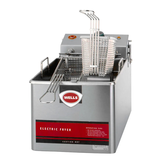
Countertop fryer
Hide thumbs
Also See for LLF-14:
- Operation manual (14 pages) ,
- Features and specifications (2 pages) ,
- Service instruction (27 pages)
Table of Contents
Advertisement
Quick Links
305
WELLS MANUFACTURING COMPANY
2 ERIK CIRCLE, P. O. Box 280
Verdi, NV 89439
Customer Service (775) 345-0444 Ext.502
fax: (775) 345-0569
www.wellsbloomfield.com
SERVICE MANUAL
SERVICE MANUAL
MODEL
MODEL
AAA-AAA
LLF-14
COUNTERTOP
FRYER
Includes:
TROUBLESHOOTING
SUGGESTIONS
SERVICING
INSTRUCTIONS
EXPLODED VIEW
PARTS LIST
WIRING DIAGRAM
IMPORTANT: WELLS MANUFACTURING PROPRIETARY INFORMATION.
DISSEMINATION OF THIS INFORMATION TO ANYONE OTHER THAN
WELLS AUTHORIZED SERVICE AGENTS IS STRICTLY PROHIBITED.
TECHNICAL CONTENT OF THIS MANUAL IS DESIGNED FOR
USE BY QUALIFIED PROFESSIONAL TECHNICIANS ONLY.
p/n 504367 Rev. (-)
S305 121001 cps
Advertisement
Table of Contents
Troubleshooting

Related Manuals for Wells LLF-14


Summary of Contents for Wells LLF-14
-
Page 1: Troubleshooting
WIRING DIAGRAM IMPORTANT: WELLS MANUFACTURING PROPRIETARY INFORMATION. DISSEMINATION OF THIS INFORMATION TO ANYONE OTHER THAN WELLS AUTHORIZED SERVICE AGENTS IS STRICTLY PROHIBITED. TECHNICAL CONTENT OF THIS MANUAL IS DESIGNED FOR USE BY QUALIFIED PROFESSIONAL TECHNICIANS ONLY. p/n 504367 Rev. (-) - Page 2 PRECAUTIONS AND GENERAL INFORMATION WARNING: This appliance is intended for use in commercial establishments only. Risk of personal injury This appliance is intended to prepare food for human consumption. No other use is recommended or authorized by the manufacturer or its Installation procedures agents.
-
Page 3: Table Of Contents
This manual contains the information needed to properly service and repair this equipment. SPECIFICATIONS MODEL VOLTS AMPS WATTS POWER CORD 120 VAC 1ø 15 A 1,800 W NEMA 5-15P LLF-14 208 VAC 1ø 16.2A 3,400W NEMA 6-30P 240 VAC 1ø 18.8A 4,500W... -
Page 4: Features & Operating Controls
FEATURES & OPERATING CONTROLS Fig. 1 LLF-14 Features & Operating Controls... -
Page 5: Operation
OPERATION DANGER: BURN HAZARD Contact with hot oil will cause severe burns. Always wear protective clothing and heat resistant gloves when operating the fryer. NORMAL OPERATION CAUTION: Hot Surface 1. a. Be sure the TEMPERATURE CONTROL KNOB is turned to OFF. -
Page 6: Troubleshooting Suggestions
TROUBLESHOOTING SUGGESTIONS DESCRIPTION POSSIBLE PROBLEM SUGGESTED REMEDY Fryer will not heat Not plugged in or circuit breaker Plug into proper receptacle tripped Reset circuit breaker Temperature control knob not set to Set to desired temperature desired temperature Hi-limit safety tripped Clean element , reset hi-limit Damaged hi-limit safety thermostat... -
Page 7: Servicing Instructions
SERVICING INSTRUCTIONS REPLACE ELEMENT CAUTION: Burn Hazard Allow fryer to cool before performing this service. CAUTION: Fig. 4 Electric Shock Element Assembly Hazard Unplug fryer from electric power before servicing. IMPORTANT: DO NOT damage the capillary tubes. If the tubes are pinched or kinked, they Unplug fryer and allow to cool before servicing. - Page 8 SERVICING INSTRUCTIONS (continued) CAUTION: REPLACE TEMPERATURE CONTROL THERMOSTAT Burn Hazard OR HI-LIMIT SAFETY THERMOSTAT Allow fryer to cool before performing this service. Fig. 7 CAUTION: Thermostat Installation Electric Shock Hazard Unplug fryer from electric power before servicing. IMPORTANT: DO NOT damage the Unplug fryer and allow to cool before servicing.
-
Page 9: Replace Support Rod Spring
SERVICING INSTRUCTIONS (continued) REPLACE SUPPORT ROD SPRING CAUTION: Burn Hazard Allow fryer to cool before performing this service. Fig. 10 Support Rod CAUTION: Spring Installation Electric Shock Hazard Unplug fryer from electric Unplug fryer and allow to cool before servicing. power before servicing. -
Page 10: Exploded View
EXPLODED VIEW Fig. 12 LLF-14 Exploded View... -
Page 11: Parts List
SPRING, SUPPORT ROD 65765 SHELL ASSEMBLY 65767 BRACKET, PIVOT 53436 WASHER, SLOTTED PIVOT 55747 GASKET, FRYER HEAD (pk 12) 65774 CONTROL BOX 55028 COVER, CONTROL BOX LABEL, HI-LIMIT RESET LABEL, FACEPLATE LOGO, WELLS DOMED 20169 FRYPOT 21506 FRY BASKET, HALF-SIZE... -
Page 12: Wiring Diagram
WIRING DIAGRAM LLF-14 FRYER WIRING DIAGRAM, 120V and 240V... - Page 13 WIRING SCHEMATIC LLF-14 FRYER SCHEMATIC, 120V and 240V...
- Page 14 IMPORTANT: WELLS MANUFACTURING PROPRIETARY INFORMATION. DISSEMINATION OF THIS INFORMATION TO ANYONE OTHER THAN WELLS AUTHORIZED SERVICE AGENTS IS STRICTLY PROHIBITED. TECHNICAL CONTENT OF THIS MANUAL IS DESIGNED FOR USE BY QUALIFIED PROFESSIONAL TECHNICIANS ONLY. WELLS MANUFACTURING COMPANY DIVISION OF CARRIER REFRIGERATION 2 ERIK CIRCLE, P.
Need help?
Do you have a question about the LLF-14 and is the answer not in the manual?
Questions and answers