
Related Manuals for Olympus CV-180


Summary of Contents for Olympus CV-180
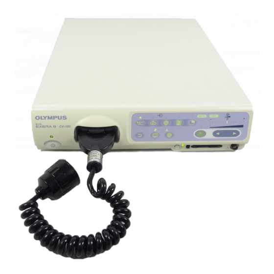
- Page 1 INSTRUCTIONS EVIS EXERA II VIDEO SYSTEM CENTER OLYMPUS CV-180 USA: CAUTION: Federal law restricts this device to sale by or on the order of a physician.
-
Page 3: Table Of Contents
Inspection of the release function ........... Inspection of the PinP (picture in picture) function......Inspection of the orientation function ..........Inspection of the special light observation function......3.10 Inspection of the scope switches and foot switches ....... EVIS EXERA II VIDEO SYSTEM CENTER CV-180... - Page 4 Image size (“F8”) ................... Printer lock (“Shift” + “F8”)..............Image enhancement (“F9”)..............White balance adjustment (“Shift” + “F9”) ..........Color tone adjustment (“COLOR”)............Freeze (“FREEZE”) ................Release (“RELEASE”)................Arrow pointer (“Shift” + arrow keys and domepoint)......EVIS EXERA II VIDEO SYSTEM CENTER CV-180...
- Page 5 Scope information ................Displaying and entering scope information........... Special light observation ..............NBI (narrow band imaging)..............Chapter 6 Fuse replacement ............ 153 Chapter 7 Care, Storage and Disposal........155 Care ....................Storage ................... Disposal ..................EVIS EXERA II VIDEO SYSTEM CENTER CV-180...
- Page 6 Iris......................Iris speed....................Auto gain control (AGC) ................ Contrast....................Exposure area ..................Electronic shutter................... Patient data display ................Scope nickname..................Release index time................Indication of the special light observation..........Monitor orientation function ..............EVIS EXERA II VIDEO SYSTEM CENTER CV-180...
- Page 7 Chapter 10 Troubleshooting ............259 10.1 Troubleshooting guide ..............10.2 Returning the video system center for repair ........Appendix ..................269 System chart .................... Transportation, storage, and operation environment ........ Specifications ................... EMC information ..................EVIS EXERA II VIDEO SYSTEM CENTER CV-180...
- Page 8 Contents EVIS EXERA II VIDEO SYSTEM CENTER CV-180...
-
Page 9: Labels And Symbols
Labels and Symbols Labels and Symbols Safety-related labels and symbols are attached on the locations shown below. If labels or symbols are missing or illegible, contact OLYMPUS. Rear panel CSA/UL marking Fuse rating Caution that only the FUSES exclusive cable can be T5AL250V connected. - Page 10 Labels and Symbols Back cover of this instruction manual Manufacturer Authorized representative in the European Community EVIS EXERA II VIDEO SYSTEM CENTER CV-180...
-
Page 11: Important Information - Please Read Before Use
Important Information — Please Read Before Use Intended use This video system center has been designed to be used with OLYMPUS camera heads, endoscopes, light sources, monitors, endo-therapy accessories and other ancillary equipment for endoscopic diagnosis, treatment and video observation. Do not use this video system center for any purpose other than its intended use. - Page 12 Wash out is the inability to see details in the endoscopic image due to excessive brightness. HDTV: High Definition Television. This is a format for high resolution video transmission featuring higher definition than the standard SDTV format. EVIS EXERA II VIDEO SYSTEM CENTER CV-180...
-
Page 13: User Qualifications
2 (IEC 60601-1-2: 2001). However, when connecting to an instrument that complies with the EMC standard for medical electrical equipment; edition 1 (IEC 60601-1-2: 1993), the whole system complies with edition 1. EVIS EXERA II VIDEO SYSTEM CENTER CV-180... -
Page 14: Repair And Modification
Some problems that appear to be malfunctions may be correctable by referring to Chapter 10, “Troubleshooting”. If the problem cannot be resolved using the information in Chapter 10, contact Olympus. This instrument is to be repaired by Olympus technicians only. -
Page 15: Dangers, Warnings And Cautions
O)) are present in the atmosphere; flammable gases are present in the atmosphere; flammable liquids are near. Otherwise, explosion or fire may result because this video system center is not explosion-proof. EVIS EXERA II VIDEO SYSTEM CENTER CV-180... - Page 16 Do not use this product in any place where it may be subject to strong electromagnetic radiation (for example, in the vicinity of a microwave therapeutic device, MRI, wireless set, short-wave therapeutic device, cellular/portable phone, etc.). This may impair the performance of the product. EVIS EXERA II VIDEO SYSTEM CENTER CV-180...
- Page 17 OFF before connecting or disconnecting the endoscope. • Clean and vacuum dust the ventilation grills using a vacuum cleaner, when necessary. Otherwise, the video system center may break down and gets damaged from overheating. EVIS EXERA II VIDEO SYSTEM CENTER CV-180...
- Page 18 Classification types are clearly specified in the instruments' instruction manuals. Symbol Classification TYPE CF applied part TYPE BF applied part TYPE B applied part EVIS EXERA II VIDEO SYSTEM CENTER CV-180...
-
Page 19: Cardiac Applications
The OLYMPUS light guide cables and camera heads listed in the “System chart” in the Appendix (TYPE CF applied part) which are suitable for cardiac applications bear a mark. -
Page 20: Summary Of Equipment Functions
“Contrast mode (“Shift” + “F6”)” on page 90 • Enhancement of edge lines and patterns of the images “Image enhancement mode (ENH.)” on page 67 • Changing the image size “Image size (“F8”)” on page 94 EVIS EXERA II VIDEO SYSTEM CENTER CV-180... - Page 21 136.) • Up to 40 sets of patients data can be stored on the PC card. These patient data can be copied to the other CV-180. “Recording patient data into PC card” on page 144 Customizing the operations Up to 20 remote switch settings and other functions such as iris mode, image enhancement, etc., can be stored.
-
Page 22: Chapter 1 Checking The Package Contents
Match all items in the package with the components shown below. Inspect each item for damage. If the instrument is damaged, a component is missing or you have any questions, do not use the instrument; immediately contact Olympus. Video system center (CV-180) -
Page 23: Chapter 2 Nomenclature And Functions
17. STOP button 20. Image enhancement 16. PC card status mode (ENH.) button indicator 19. Iris mode indicators 15. Eject button 14. PC card slot 18. Iris mode (IRIS) button 13. PinP composite terminal EVIS EXERA II VIDEO SYSTEM CENTER CV-180... - Page 24 Lights up green when the NBI compatible endoscope is connected to this instrument, and turns white during NBI observation. This indicator works only when the light source CLV-180 is used. “NBI (narrow band imaging)” on page 151 EVIS EXERA II VIDEO SYSTEM CENTER CV-180...
- Page 25 Either “AUTO” or “PEAK” mode can be selected. • Presetting “Iris” on page 232 • Switching operation “Iris mode” on page 69 19. Iris mode indicators Indicates the iris mode being selected. EVIS EXERA II VIDEO SYSTEM CENTER CV-180...
- Page 26 The indicator goes off when the image enhancement is not used. 22. RESET button Press and hold the switch to return the settings changed during operation to the default settings. “RESET button” on page 80 EVIS EXERA II VIDEO SYSTEM CENTER CV-180...
-
Page 27: Rear Panel
22. Monitor OUT terminal 15. Light source terminal 21. Composite OUT terminal 16. PinP Y/C terminal 20. Monitor remote terminal 17. HD/SD SDI OUT terminal 19. PC OUT2 terminal 18. Digital OUT terminal EVIS EXERA II VIDEO SYSTEM CENTER CV-180... - Page 28 10. Foot switch terminal Connect the foot switch. 11. VCR remote terminal Connect an Olympus-recommended VCR. Outputs the analog video signal and the remote signals to the VCR. 12. Fuse box Stores the fuses that protect the instrument from electrical surges.
- Page 29 Connect a monitor compatible with the serial digital interface (SDI). Outputs the SDI signal. 18. Digital OUT terminal Connect an Olympus-recommended digital video recorder to output and input the digital video signal to the digital video recorder, using IEEE1394 cable.
-
Page 30: Keyboard
11. F11 key 7. F7 key 14. Scroll lock key 2. F2 key 10. F10 key 6. F6 key 13. Print screen key 1. F1 key 9. F9 key 5. F5 key 27. Arrow keys EVIS EXERA II VIDEO SYSTEM CENTER CV-180... - Page 31 “Image zooming (“F7”)” on page 91 Press together with the “Shift” key to display the color bar for checking the color of the monitor. “Color bar (“Shift” + “F7”)” on page 93 EVIS EXERA II VIDEO SYSTEM CENTER CV-180...
- Page 32 An arbitrary number “N” on the keyboard depends on the printer. Section5.5, “Printing images” on page 131 17. CAPTURE key Press to capture the image in the video printer. Section5.5, “Printing images” on page 131 EVIS EXERA II VIDEO SYSTEM CENTER CV-180...
- Page 33 Press this key to enter an item after selecting the item using the domepoint. “Domepoint” on page 81 26. Domepoint Moves the arrow pointer. Selects an item in the menu or puts a marking in the endoscopic image. “Domepoint” on page 81 EVIS EXERA II VIDEO SYSTEM CENTER CV-180...
- Page 34 Fixes entry and goes to the next text box or screen. • Shift, Alt Executes functions together with other keys. • Back space Clears the character left of the cursor. • Delete Clears the character right of the cursor. EVIS EXERA II VIDEO SYSTEM CENTER CV-180...
-
Page 35: Side Panels
Connect to the video system center “UP” side up. Video plug Scope side connector Connect to the video Connect to the scope connector socket of the connector of the endoscope. video system center. EVIS EXERA II VIDEO SYSTEM CENTER CV-180... -
Page 36: Set-Up Of Screen Options
Section 5.7, “Scope information” on page 148 • Color bar screen This screen is used to check the display color. “Color bar (“Shift” + “F7”)” on page 93 EVIS EXERA II VIDEO SYSTEM CENTER CV-180... -
Page 37: Monitor
The status of the image recording devices that record and print the image are displayed only when the recording devices are activated. Indication Device Details Video printer page 131 Digital filing system page 127 Videocassette recorder page 129 EVIS EXERA II VIDEO SYSTEM CENTER CV-180... - Page 38 Zoom ratio page 91 5. Flushing pump Displayed only when the Olympus flushing pump (OFP) is processing. 6. PC card capacity Indicates the remaining memory level of the PC card when the PC card is inserted in the PC card slot.
- Page 39 Chapter 2 Nomenclature and Functions 14. Scope nickname The scope nickname is displayed when an endoscope with a scope nickname function is connected. “Scope nickname” on page 242 EVIS EXERA II VIDEO SYSTEM CENTER CV-180...
- Page 40 Scroll bar Shows all setting values not being displayed in the list box. Arrow pointer Moves the cursor, selects the function buttons, displays the pull down menus. EVIS EXERA II VIDEO SYSTEM CENTER CV-180...
-
Page 41: Pointer
Always displayed on image screen (unless full image screen selected). Press “Shift” and any arrow key in the full image screen to display/remove the arrow pointer. • Endoscopic image Press “Shift” and any arrow key. screen EVIS EXERA II VIDEO SYSTEM CENTER CV-180... -
Page 42: Chapter 3 Inspection
Prepare the video system center and other ancillary equipment before each particular case. Refer to the respective instruction manual for each piece of equipment. EVIS EXERA II VIDEO SYSTEM CENTER CV-180... -
Page 43: Inspection Of The Power Supply
When the power fails to come ON, turn the video system center OFF. Then check the video system center referring to Chapter 10, “Troubleshooting”. If the power still fails to come ON, contact Olympus. EVIS EXERA II VIDEO SYSTEM CENTER CV-180... -
Page 44: Inspection Of The Examination Light
Turn ON the light source and confirm that examination light is emitted from the distal end of the endoscope (see Figure 3.2). For operation of the light source, refer to its instruction manual. Endoscope’s distal end Examination light Figure 3.2 EVIS EXERA II VIDEO SYSTEM CENTER CV-180... -
Page 45: Inspection Of The Automatic Brightness Control Function
• Depending on the light source connected, the exposure level indicator on the video system center goes off. Control the brightness on the light source referring to “Brightness adjustment (Exposure)” on page 71. EVIS EXERA II VIDEO SYSTEM CENTER CV-180... -
Page 46: Inspection Of The Monitor Display
Confirm that enough space is available on the PC card to store endoscopic images. • The display layout is variable according to the connected endoscope and user preset. • For setting the date or time, refer to “Date and time” on page 197. EVIS EXERA II VIDEO SYSTEM CENTER CV-180... -
Page 47: Inspection Of The Freeze Function
Inspection of the orientation function If the orientation function is activated, confirm that the indication on the monitor is an endoscopic image rotated by 180 (refer to “Monitor orientation function” on page 245). EVIS EXERA II VIDEO SYSTEM CENTER CV-180... -
Page 48: Inspection Of The Special Light Observation Function
If any function is assigned to the scope's remote switches and/or foot switches, confirm the proper function of these switches. 3.11 Power OFF Press the power switch of the instrument (see Figure 3.1) to turn the instrument OFF. The indicator above the switch goes off. EVIS EXERA II VIDEO SYSTEM CENTER CV-180... -
Page 49: Chapter 4 Operation
OFF. Then, gently withdraw the endoscope from the patient as described in the endoscope's instruction manual. EVIS EXERA II VIDEO SYSTEM CENTER CV-180... - Page 50 • Do not use a humidifier near the video system center as dew condensation possibly might occur and it may cause equipment failure. EVIS EXERA II VIDEO SYSTEM CENTER CV-180...
- Page 51 High-frequency electrosurgical equipment can cause slight interference on the monitor display. • Sometimes horizontal line noise appears when a slim endoscope is used. To reduce the horizontal line noise, select “Edge enhancement” for the enhancement setting. EVIS EXERA II VIDEO SYSTEM CENTER CV-180...
-
Page 52: Operation Flow
6. Enter the patient data. Section 4.6, “Patient data” on page 57 It is possible to enter the patient data before the examination (see “Entering new patient data” on page 137). continued on next page EVIS EXERA II VIDEO SYSTEM CENTER CV-180... - Page 53 8. Terminate the examination. Section 4.9, “Termination of the operation” on page 60 Press “EXAM END” key after the examination. Then turn the CV-180 and other instruments OFF. 9. Disconnect the endoscope from the video system center and the light source. ...
-
Page 54: Connection Of An Endoscope
• Be sure to refer to the instruction manuals of the ancillary equipment including the endoscope and camera cable. EVIS EXERA II VIDEO SYSTEM CENTER CV-180... - Page 55 Confirm that the “UP” mark points upwards (see Figure 4.3). Connect the scope side connector of the scope cable EXERA II to the endoscope, referring to the instruction manual of the endoscope. EVIS EXERA II VIDEO SYSTEM CENTER CV-180...
- Page 56 Confirm that the “UP” mark points upwards (see Figure 4.3). Attach the light guide cable, video adapter and camera head to the rigidscope, referring to the instruction manuals for the light guide cable, video adapter and camera head. EVIS EXERA II VIDEO SYSTEM CENTER CV-180...
- Page 57 VISERA series Videoscope cable EXERA II EVIS series and ultrasonic videoscope Video adapter Camera head Fiberscopes Light guide cable Video adapters, camera heads, etc. Rigidscope The numbers show the order of connection. Figure 4.4 EVIS EXERA II VIDEO SYSTEM CENTER CV-180...
-
Page 58: Turning The Video System Center On
The endoscopic image appears on the monitor (see Figure 4.6). Name: Sex: Age: D.O.B. 12/12/2005 12:12:12 Physician: Comment: Figure 4.6 For the procedure of turning the ancillary equipment ON, refer to each instrument's instruction manual. EVIS EXERA II VIDEO SYSTEM CENTER CV-180... -
Page 59: Recall Of User Preset Data
Check if the correct user name is selected, then click “Select”. The endoscopic image appears on the monitor and the user preset data is loaded to the video system center. EVIS EXERA II VIDEO SYSTEM CENTER CV-180... -
Page 60: White Balance Adjustment
Otherwise, cross- contamination may result. • Always control the color tone and/or enhancement of the image appropriately before observation. Setting an inappropriate color tone or enhancement condition may result in overlooking or wrong diagnosis. EVIS EXERA II VIDEO SYSTEM CENTER CV-180... - Page 61 Wh/B OK indicator Wh/B button Figure 4.9 “Wh/B OK” indicator Status of white balance adjustment Before adjustment or if adjustment failed. Completed. Table 4.1 Proceed as follows according to the use of the endoscope. EVIS EXERA II VIDEO SYSTEM CENTER CV-180...
- Page 62 Confirm that the “Wh/B OK” indicator is ON (see Table 4.1). If it is OFF, go back to step 1. again. When performing white balance adjustment keep an appropriate distance between distal end and white cap. Otherwise, the white balance might not be adjusted properly. EVIS EXERA II VIDEO SYSTEM CENTER CV-180...
- Page 63 Hold the endoscope as shown in step 1. of “When using an endoscope for the non-sterilized zone” on page 54 or step 1. of “When using an endoscope for the sterilized zone” on page 55 according to the use of it. EVIS EXERA II VIDEO SYSTEM CENTER CV-180...
- Page 64 The white balance adjustment can also be initiated from the endoscope's remote switches and/or foot switches. For how to set up the remote switches and foot switches, see “Remote switch and foot switch (EXERA and VISERA)” on page 219 EVIS EXERA II VIDEO SYSTEM CENTER CV-180...
-
Page 65: Patient Data
Press the “F1” key to change the monitor display full-patient-data display. Press the “EXAM END” key to clear the previous patient data. Name: Sex: Age: Cursor D.O.B. 12/12/2005 12:12:12 Physician: Comment: Figure 4.11 EVIS EXERA II VIDEO SYSTEM CENTER CV-180... - Page 66 When modifying data, press the arrow key to move the cursor to the input position and edit the data. When deleting all patient data displayed on the monitor, press the “EXAM END” key on the keyboard (see Figure 4.13). EXAM END Figure 4.13 EVIS EXERA II VIDEO SYSTEM CENTER CV-180...
-
Page 67: Observation Of The Endoscopic Image
Section 5.3, “Image recording and playback (PC card)” on page 106 Digital file system “Image filing system” on page 127 Videocassette recorder “Videocassette recorder (VCR)” on page 129 Video printer Section 5.5, “Printing images” on page 131 Table 4.6 EVIS EXERA II VIDEO SYSTEM CENTER CV-180... -
Page 68: Termination Of The Operation
B in Figure 4.15. Video plug Scope side connector Scope cable holder Videoscope cable A) When the scope side connector B) When both connectors are is not connected. not connected. Figure 4.15 EVIS EXERA II VIDEO SYSTEM CENTER CV-180... - Page 69 Disconnect the video plug of the videoscope cable from the instrument, holding the instrument with a hand so that it will not move and push the locking lever down (see Figure 4.16). Video connector socket Locking lever Video plug Figure 4.16 EVIS EXERA II VIDEO SYSTEM CENTER CV-180...
-
Page 70: Chapter 5 Functions
Images on the monitor Front panel Rear panel SCOPE Endoscope’s live image Scope connector DV/VCR VCR, video recorder VCR REMOTE or DIGITAL OUT Digital filing system PC IN PRINTER Video printer PRINTER IN Table 5.1 EVIS EXERA II VIDEO SYSTEM CENTER CV-180... - Page 71 When pressing PC button, the image input from PC IN terminal is selected, regardless of the PC’s connection. EVIS EXERA II VIDEO SYSTEM CENTER CV-180...
-
Page 72: Pinp (Picture In Picture) Display
PinP Y/C terminal on the rear panel (see Figure 5.2). PinP button SCOPE button PinP composite terminal Front panel PinP Y/C terminal Rear panel Figure 5.2 Press the “SCOPE” button to display the endoscopic live image. EVIS EXERA II VIDEO SYSTEM CENTER CV-180... - Page 73 External Endoscopic image image PinP button PinP button Screen transition in the “ON/OFF mode” Note) The initial screen when pressing the PinP button depends on the user settings preset. Figure 5.4 EVIS EXERA II VIDEO SYSTEM CENTER CV-180...
- Page 74 Before activating the PinP function make sure that an endoscope is connected to this instrument. If no endoscope is connected it might not be possible to use the PinP function and image recording of an external device may not work. EVIS EXERA II VIDEO SYSTEM CENTER CV-180...
-
Page 75: Image Enhancement Mode (Enh.)
“ENH.” button. The indicator above the button goes OFF. ENH. button ENH. button ENH. button Enhancement ENH. button Mode 1 Mode 2 Mode 3 Press and hold ENH. button Enhancement ON Figure 5.7 EVIS EXERA II VIDEO SYSTEM CENTER CV-180... - Page 76 The image enhancement function can also be controlled from the scope switches and/or foot switches. For how to set up the scope switches and foot switches, see “Remote switch and foot switch (EXERA and VISERA)” on page 219. EVIS EXERA II VIDEO SYSTEM CENTER CV-180...
-
Page 77: Iris Mode
The iris mode can also be controlled from the scope switches and/or foot switches. For how to set up the scope switches and foot switches, see “Remote switch and foot switch (EXERA and VISERA)” on page 219. EVIS EXERA II VIDEO SYSTEM CENTER CV-180... -
Page 78: White Balance
The white balance adjustment can also be controlled from the scope switches and/or foot switches. For how to set up the scope switches and foot switches, see “Remote switch and foot switch (EXERA and VISERA)” on page 219. EVIS EXERA II VIDEO SYSTEM CENTER CV-180... -
Page 79: Brightness Adjustment (Exposure)
The light intensity reaches its greatest value, and excessive heat of the endoscope's distal end may occur. Adjust the brightness using the The “EXPOSURE” indicator brightness adjustment buttons on the goes OFF. light source. Table 5.2 EVIS EXERA II VIDEO SYSTEM CENTER CV-180... - Page 80 Disconnecting them can increase the light intensity to the maximum and may cause burns or eye injury. Refer to the instruction manual of the endoscope for details of the electric shutter function. EVIS EXERA II VIDEO SYSTEM CENTER CV-180...
- Page 81 The “EXPOSURE” indication is interlocked with the brightness level indication of the connected CLV-180. When the brightness adjustment buttons on the CLV-180 are pressed, the “EXPOSURE” indication on the video system center varies in an interlocked operation. EVIS EXERA II VIDEO SYSTEM CENTER CV-180...
- Page 82 Set the brightness as required, using the brightness adjustment buttons of the light source. The brightness level is displayed on the light source. The “EXPOSURE” buttons of the video system center is invalid, and the “EXPOSURE” indicator goes OFF. EVIS EXERA II VIDEO SYSTEM CENTER CV-180...
-
Page 83: Stop Button And Pc Card Indicator
“STOP” button. Press the eject button to eject the PC card after a few seconds, then insert the PC card again to let the video system center recognize the PC card. EVIS EXERA II VIDEO SYSTEM CENTER CV-180... -
Page 84: Pc Card Slot And Eject Button
PC card may not be possible. Format the PC card before the first use as described in “Formatting of the PC card” on page 114. Use the CV-180 for formatting the PC card. Do not use a personal computer, etc. •... - Page 85 Push the PC card adapter all the way into the PC card slot. PC card status indicator PC card adapter Figure 5.13 The video system center recognizes the PC card, and the PC card status indicator lights up green. EVIS EXERA II VIDEO SYSTEM CENTER CV-180...
- Page 86 PC card slot. Otherwise, the PC card and/or data stored may be destroyed. Press the “STOP” button. The PC card status indicator goes OFF (see Figure 5.14). STOP button Eject button PC card status indicator Figure 5.14 Press the eject button. EVIS EXERA II VIDEO SYSTEM CENTER CV-180...
- Page 87 Chapter 5 Functions Press the eject button again. The PC card adapter comes out slightly (see Figure 5.15). Eject button PC card adapter Figure 5.15 Pull the PC card adapter straight out. EVIS EXERA II VIDEO SYSTEM CENTER CV-180...
-
Page 88: Reset Button
Table 5.5 Press and hold the “RESET” button on the front panel (see Figure 5.16). All front panel indicators should blink for about 1 second, then the settings are reset. RESET button Figure 5.16 EVIS EXERA II VIDEO SYSTEM CENTER CV-180... -
Page 89: Keyboard
Time Date Date The cursor moves. Click the text box to place the cursor. Figure 5.18 Click a button on the menu to move the highlight, or perform the function of the button. EVIS EXERA II VIDEO SYSTEM CENTER CV-180... -
Page 90: Clearing Characters From The Screen ("F1")
The patient data can also be cleared using the scope switches and/or foot switches. For how to set up the scope switches and foot switches, see “Remote switch and foot switch (EXERA and VISERA)” on page 219. EVIS EXERA II VIDEO SYSTEM CENTER CV-180... - Page 91 Z: x1.5 Ct: N Eh: A8 Press F1 key Pump Z: x1.5 Media: Pump Media: John Smith John Smith Cardiac end of the stomach Cardiac end of the stomach Figure 5.20 EVIS EXERA II VIDEO SYSTEM CENTER CV-180...
-
Page 92: System Setup ("Shift" + "F1")
Section 9.2, “System setup” on page 194. Shift Figure 5.21 Scope information (“F2”) Press this key to open the scope information window. For details, see Section 5.7, “Scope information” on page 148. Figure 5.22 EVIS EXERA II VIDEO SYSTEM CENTER CV-180... -
Page 93: User Preset ("Shift" + "F2")
(operator). For details on the user preset menu, see Section 9.3, “User preset” on page 216. Shift Figure 5.23 Cursor (“F3”) Press to switch the display of the cursor on the screen between ON and OFF. Figure 5.24 EVIS EXERA II VIDEO SYSTEM CENTER CV-180... -
Page 94: Patient Data ("Shift" + F3)
Figure 5.26 The freeze mode switches between “frame” and “field” each time the “F4” key is pressed. For more information of the freeze mode, see “Freeze function” on page 225. EVIS EXERA II VIDEO SYSTEM CENTER CV-180... -
Page 95: Browse ("Shift" + "F4")
PC card. See “PC card menu” on page 110. Press the “Shift” and “F4” keys together to open the PC card menu. Shift Figure 5.27 Figure 5.28 EVIS EXERA II VIDEO SYSTEM CENTER CV-180... -
Page 96: Stopwatch ("F5")
The stopwatch operation can also be controlled from the scope switches and/or foot switches. For how to set up the scope switches and foot switches, see “Remote switch and foot switch (EXERA and VISERA)” on page 219. EVIS EXERA II VIDEO SYSTEM CENTER CV-180... -
Page 97: Automatic Gain Control (Agc) ("F6")
The AGC switching operation can also be controlled from the scope switches and/or foot switches. For how to set up the scope switches and foot switches, see “Remote switch and foot switch (EXERA and VISERA)” on page 219. EVIS EXERA II VIDEO SYSTEM CENTER CV-180... -
Page 98: Contrast Mode ("Shift" + "F6")
N: Normal Pump Media: H: High Contrast Normal L: Low John Smith Cardiac end of the stomach Figure 5.35 • The contrast mode function does not work during the special light observation. EVIS EXERA II VIDEO SYSTEM CENTER CV-180... -
Page 99: Image Zooming ("F7")
CVP: A4/4 D.F: 99 Ct: N Eh: A8 Z: x1.5 Pump x1.2 x1.5 Media: Zoom x 1.5 John Smith Transition of the zoom ratio Cardiac end of the stomach (example) Figure 5.37 EVIS EXERA II VIDEO SYSTEM CENTER CV-180... - Page 100 The zoom ratio can also be controlled from the scope switches and/or foot switches. For how to set up the scope switches and foot switches, see “Remote switch and foot switch (EXERA and VISERA)” on page 219. EVIS EXERA II VIDEO SYSTEM CENTER CV-180...
-
Page 101: Color Bar ("Shift" + "F7")
Press the “Shift” and “F7” keys together (see Figure 5.39). The color bar appears on the monitor (see Figure 5.40). Shift Figure 5.39 Color bar Figure 5.40 Confirm that all colors of the color chart are displayed properly. EVIS EXERA II VIDEO SYSTEM CENTER CV-180... -
Page 102: Image Size ("F8")
The image size selection operation can also be controlled from the scope switches and/or foot switches. For how to set up the scope switches and foot switches, see “Remote switch and foot switch (EXERA and VISERA)” on page 219. EVIS EXERA II VIDEO SYSTEM CENTER CV-180... -
Page 103: Printer Lock ("Shift" + "F8")
Press the “Shift” and “F8” keys together to lock the “PRINTER REMOTE” keys. DEL IMAGE PRINT PRINT QTY. CAPTURE #PER PAGE PRINTER REMOTE Shift Figure 5.42 To unlock the keys, press the “Shift” and “F8” keys together again. EVIS EXERA II VIDEO SYSTEM CENTER CV-180... -
Page 104: Image Enhancement ("F9")
Mike Johnson 03/03/1954 Image enhancement 12/12/2005 indication 12:12:12 CVP: A4/4 D.F: 99 Image enhancement Ct: N Eh: A8 window Z: x1.5 Pump Media: Enhance:A1 John Smith Cardiac end of the stomach Figure 5.44 EVIS EXERA II VIDEO SYSTEM CENTER CV-180... -
Page 105: White Balance Adjustment ("Shift" + "F9")
The white balance adjustment can also be initiated from the scope switches and/or foot switches. For how to set up the scope switches and foot switches, see “Remote switch and foot switch (EXERA and VISERA)” on page 219. EVIS EXERA II VIDEO SYSTEM CENTER CV-180... -
Page 106: Color Tone Adjustment ("Color")
OFF. • When the video system center is turned ON, the color tone used in the last operation before the instrument is turned OFF comes up when the instrument is turned ON. EVIS EXERA II VIDEO SYSTEM CENTER CV-180... -
Page 107: Freeze ("Freeze")
A frozen image in the frame freeze mode is more easily blurred than in the field freeze mode. • During freezing, the size of the image area and image enhancement can be changed. EVIS EXERA II VIDEO SYSTEM CENTER CV-180... - Page 108 The image freeze operation can also be controlled from the scope switches and/or foot switches. For how to set up the scope switches and foot switches, see “Remote switch and foot switch (EXERA and VISERA)” on page 219. EVIS EXERA II VIDEO SYSTEM CENTER CV-180...
-
Page 109: Release ("Release")
Mike Johnson 03/03/1954 12/12/2005 Image filing system 12:12:12 CVP: A4/4 D.F: 99 PC card Ct: N Eh: A8 Z: x1.5 Pump Media: John Smith Cardiac end of the stomach Figure 5.50 EVIS EXERA II VIDEO SYSTEM CENTER CV-180... -
Page 110: Arrow Pointer ("Shift" + Arrow Keys And Domepoint)
Press “Shift” and any arrow key in the full image screen. Table 5.7 Press the “Shift” and any arrow key (see Figure 5.51). The arrow pointer appears in the center of the endoscopic image (see Figure 5.52). Domepoint Arrow keys Shift Figure 5.51 EVIS EXERA II VIDEO SYSTEM CENTER CV-180... - Page 111 The arrow pointer can also be displayed and cleared from the scope switches and/or foot switches. For how to set up the scope switches and foot switches, see “Remote switch and foot switch (EXERA and VISERA)” on page 219. EVIS EXERA II VIDEO SYSTEM CENTER CV-180...
-
Page 112: Color Mode ("Shift" + "Alt" + "1", "2", "3", "4")
Less reddish color than the Mode 1 Shift + Alt + 3 Mode 3 More yellowish color than the Mode 1 Shift + Alt + 4 Mode 4 Standard color mode Table 5.8 EVIS EXERA II VIDEO SYSTEM CENTER CV-180... -
Page 113: Ending Examination ("Exam End")
(e.g. to the PC card) is stopped. EXAM END Figure 5.53 The patient name that is once displayed in the endoscopic image turns gray in the patient list after finishing the observation by pressing the “EXAM END” key. EVIS EXERA II VIDEO SYSTEM CENTER CV-180... -
Page 114: Image Recording And Playback (Pc Card)
Otherwise, recording cannot be performed properly. See “Formatting of the PC card” on page 114. • Be sure to format the PC card using the CV-180. The PC card that is formatted by a personal computer may cause malfunction in recording or playback. - Page 115 30 images, a message appears on the screen (see Figure 5.55). ABC123 Mike Johnson 03/03/1954 12/12/2005 Message window of the 12:12:12 storage level of the PC card Media: Media: John Smith Cardiac end of the stomach Figure 5.55 EVIS EXERA II VIDEO SYSTEM CENTER CV-180...
-
Page 116: Recording The Frozen Image On A Pc Card
• If the video system center is turned OFF or the “STOP” button is pressed during recording, the images on the video system center will be lost. EVIS EXERA II VIDEO SYSTEM CENTER CV-180... - Page 117 (EXERA and VISERA)” on page 219. • The main and sub images of PinP are recorded on the PC card as the separated files that have the same time stamp. EVIS EXERA II VIDEO SYSTEM CENTER CV-180...
-
Page 118: Pc Card Menu
See page 119. Normal screen See page 115. Title See page 122. Back, Preview Zoom Annotation preview screen See page 119. Full screen Title See page 115. Shift + F4 Figure 5.58 EVIS EXERA II VIDEO SYSTEM CENTER CV-180... -
Page 119: Basic Operation Of The Pc Card Menu
76. Press the “Shift” and “F4” keys together (see Figure 5.60). The message “Please wait” is displayed on the monitor, then the folder list screen appears (see Figure 5.61). Shift Figure 5.60 EVIS EXERA II VIDEO SYSTEM CENTER CV-180... - Page 120 (see Figure 5.62). The thumbnail-sized images for the annotation image is not an image but an icon. Thumbnail image Annotation icon Figure 5.62 Perform file operation such as playback and deletion of images, etc. EVIS EXERA II VIDEO SYSTEM CENTER CV-180...
- Page 121 The aspects ratio of a thumbnail image depends on the endoscope used. • Refer to “Image files and folders” on page 125 for the details of the folder names shown in the folder list screen. EVIS EXERA II VIDEO SYSTEM CENTER CV-180...
-
Page 122: Formatting Of The Pc Card
Chapter 5 Functions Formatting of the PC card • Be sure to format the PC card using the CV-180. If it is formatted by an other instrument such as a personal computer, it may not be possible to record or playback images from the PC card. -
Page 123: Playback Images From The Pc Card
(see Figure 5.65). Figure 5.65 Click “<” or “>” to playback the images before and after the image currently being played back. EVIS EXERA II VIDEO SYSTEM CENTER CV-180... - Page 124 • The images edited by a personal computer or an instrument other than the CV-180 may be unable to be played back. • The endoscopic image and the patient data is displayed together on the same screen when using the CV-180 for playing back, but cannot be displayed together on a personal computer.
-
Page 125: Deleting Images From A Pc Card
Or press the “Shift” and “F4” keys together to return to the endoscopic image. It is also possible to delete the image by displaying the image in the normal screen in step 2. and then clicking “Delete”. EVIS EXERA II VIDEO SYSTEM CENTER CV-180... -
Page 126: Deleting Folder From Pc Card
Click “No” to go back to the folder list screen instead of deleting. Click “Yes” to delete the selected folder. Click “Back”, press the “Esc” key, or press the “Shift” and “F4” keys together to return to the endoscopic image. EVIS EXERA II VIDEO SYSTEM CENTER CV-180... -
Page 127: Annotation Of Images
Click the required thumbnail image. The selected image is edged with a thick frame. The shooting date and time of the image are displayed on the right side of the window (see Figure 5.70). EVIS EXERA II VIDEO SYSTEM CENTER CV-180... - Page 128 • The images that are assigned with the position buttons are edged with a thick frame in the following colors: “1/4”: Pink “2/4”: Blue “3/4”: Green “4/4”: Yellow EVIS EXERA II VIDEO SYSTEM CENTER CV-180...
- Page 129 Click “Back” or press the “Esc” key to return to the annotation selection screen. Or press the “Shift” and “F4” keys together to return to the endoscopic image. All annotation images including HDTV images are displayed and saved in SDTV format. EVIS EXERA II VIDEO SYSTEM CENTER CV-180...
-
Page 130: Playback Image Annotation
Click “Yes” to print the images with the patient data and the comment. Click “Back” or press the “Esc” key to return to the thumbnail screen. Or press the “Shift” and “F4” keys together to return to the endoscopic image. EVIS EXERA II VIDEO SYSTEM CENTER CV-180... - Page 131 When the type of printer is “Foot switch” in Table 9.8 on page 202, the “Print” function does not work. • When “Yes” is selected in step 5., the un-printed images in the memory of the printer are cleared. EVIS EXERA II VIDEO SYSTEM CENTER CV-180...
-
Page 132: Playback The Images Using The Personal Computer
The file names that are displayed by other than the xml. file are different from those in Figure 5.75. • The images cannot be displayed in the PinP style. EVIS EXERA II VIDEO SYSTEM CENTER CV-180... -
Page 133: Image Files And Folders
1 For the resume function, see “Patient data display” on page 241. 2 The shaded region is used for recording the images into the same folder after swapping the endoscope during the observation. Table 5.11 EVIS EXERA II VIDEO SYSTEM CENTER CV-180... - Page 134 PC card. • The recording speed decelerates when the number of images in a folder exceeds 100, or when the number of folders on a PC card exceeds 100. EVIS EXERA II VIDEO SYSTEM CENTER CV-180...
-
Page 135: Image Recording And Playback (Other Than Pc Card)
The D.F. counter on the monitor increments by one (see Figure 5.77). When the index image setting is ON, the index image is displayed at the lower left corner on the monitor. EVIS EXERA II VIDEO SYSTEM CENTER CV-180... - Page 136 The freeze and release operations can also be controlled from the scope switches and/or foot switches. For how to set up the scope switches and foot switches, see “Remote switch and foot switch (EXERA and VISERA)” on page 219. EVIS EXERA II VIDEO SYSTEM CENTER CV-180...
-
Page 137: Videocassette Recorder (Vcr)
(see Figure 5.78). “VCR” appears on the monitor during VCR recording (see Figure 5.79). After turning the DVO-1000MD ON and right after disk insertion “Now Loading ...” is displayed. During this initialization process images cannot be recorded. EVIS EXERA II VIDEO SYSTEM CENTER CV-180... - Page 138 The recording and pause operations can also be controlled from the scope switches and/or foot switches. For how to set up the scope switches and foot switches, see “Remote switch and foot switch (EXERA and VISERA)” on page 219. EVIS EXERA II VIDEO SYSTEM CENTER CV-180...
-
Page 139: Printing Images
Sets the number of sheets to be printed. Shift + F8 Locks the 5 printer remote keys and allows the video printer (Printer lock) to be operated by using the keys on the video printer. Table 5.13 EVIS EXERA II VIDEO SYSTEM CENTER CV-180... - Page 140 Press the “FREEZE” key to freeze the endoscopic live image. Check the frozen image if it is suitable for recording. If not, press the “FREEZE” key again to return to the live image and repeat steps 2. and 3. EVIS EXERA II VIDEO SYSTEM CENTER CV-180...
- Page 141 Figure 5.82 Press the “CAPTURE” key or “RELEASE” key to overwrite the new image on the previous image. The CVP counter on the monitor increments by one (see Figure 5.81). EVIS EXERA II VIDEO SYSTEM CENTER CV-180...
- Page 142 The CAPTURE and RELEASE operations can also be controlled from the scope switches and/or foot switches. For how to set up the scope switches and foot switches, see “Remote switch and foot switch (EXERA and VISERA)” on page 219. EVIS EXERA II VIDEO SYSTEM CENTER CV-180...
- Page 143 UP-2950MD (SONY) Sheet partition Full size Indication of number of images UP-5000MD (SONY) UP-5200MD (SONY) UP-5250MD (SONY) Sheet partition Full size Indication of number of images UP-21MD (SONY) Sheet partition Full size Table 5.15 EVIS EXERA II VIDEO SYSTEM CENTER CV-180...
-
Page 144: Pre-Entry Of Patient Data
Max. 20 alphanumeric and symbol characters Table 5.16 Basic operation in the patient menu Press the “Shift” and “F3” keys together. The “Patient Data” menu appears on the monitor (see Figure 5.84). Shift Figure 5.83 Figure 5.84 EVIS EXERA II VIDEO SYSTEM CENTER CV-180... -
Page 145: Entering New Patient Data
Click “Back” to return to the endoscopic image. Entering new patient data Press the “Shift” and “F3” keys together to display “Patient Data” menu (see Figure 5.85). Figure 5.85 Click “No data” in the patient name list (see Figure 5.85). EVIS EXERA II VIDEO SYSTEM CENTER CV-180... - Page 146 Click each text box to place the cursor. Enter the data in the text boxes (see Figure 5.87). Figure 5.87 Click “OK” to register the entered data. The next patient data input screen appears. EVIS EXERA II VIDEO SYSTEM CENTER CV-180...
- Page 147 • If an error message is displayed, check if the entered data is correct. • To enter the patient data at the time of examination, see Section 4.6, “Patient data” on page 57. EVIS EXERA II VIDEO SYSTEM CENTER CV-180...
-
Page 148: Displaying Patient Data
Click “Select”. The selected patient data is displayed on the endoscopic image. The patient name that is once displayed in the endoscopic image turns gray in the patient name dialog box after finishing observation by pressing the “EXAM END” key. EVIS EXERA II VIDEO SYSTEM CENTER CV-180... -
Page 149: Editing Previously Entered Patient Data
Click the data to be modified and place the cursor in the data area. Enter the data in the text boxes. Click “OK” to register the entered data. Click “Back” to return to the endoscopic image. EVIS EXERA II VIDEO SYSTEM CENTER CV-180... -
Page 150: Deleting Previously Entered Patient Data
Click “Yes” to delete the selected patient data. The patient name selected in the patient name dialog box changes to “No data” (see Figure 5.93). Figure 5.93 Click “Back” to return to the endoscopic image. EVIS EXERA II VIDEO SYSTEM CENTER CV-180... -
Page 151: Clearing All Patient Data Previously Entered
Click “Yes” to delete all patient data, and all names in the patient name dialog box changes to “No data” (see Figure 5.95). Figure 5.95 Click “Back” to return to the endoscopic image. EVIS EXERA II VIDEO SYSTEM CENTER CV-180... -
Page 152: Recording Patient Data Into Pc Card
Recording patient data into PC card The patient data that is entered in the video system center can be saved on the PC card. The recorded patient data can be transferred to another CV-180 using the PC card. Be sure to confirm that there is no necessary patient data on the PC card which needs to be saved. - Page 153 Click “No” to return to step 2. Click “Back” to return to the endoscopic image. All 40 patient data on the PC card are overwritten. EVIS EXERA II VIDEO SYSTEM CENTER CV-180...
-
Page 154: Loading Patient Data From Pc Card
Press the “Shift” and “F3” keys together to display the PC card menu on the monitor (see Figure 5.99). Figure 5.99 Click “Load” (see Figure 5.99). A confirmation message appears on the monitor. EVIS EXERA II VIDEO SYSTEM CENTER CV-180... - Page 155 PC card. The PC card status indicator on the front panel blinks amber during recording. Click “Back” to return to the endoscopic image. All 40 patients data are registered into the video system center. Previous data disappear. EVIS EXERA II VIDEO SYSTEM CENTER CV-180...
-
Page 156: Scope Information
The following endoscopes are equipped with the scope ID function; EVIS EXERA II series endoscopes EVIS EXERA 160 series or later endoscopes (1 The items are not supported.) Some endoscopes of the VISERA series EVIS EXERA II VIDEO SYSTEM CENTER CV-180... -
Page 157: Displaying And Entering Scope Information
:2.8 2:Iris Channel Displays serial no., forceps channel diameter, :9.8 3:Enhance Distal End distal end diameter and insertion part diameter. John Smith :9.8 4:Release Insertion Tube Cardiac end of the stomach Figure 5.101 EVIS EXERA II VIDEO SYSTEM CENTER CV-180... - Page 158 Click “Back” to return to the endoscopic image. While the message “Please wait” is displayed, do not turn OFF the video system center. To cancel the input, click “Back” to return to the endoscopic image display. EVIS EXERA II VIDEO SYSTEM CENTER CV-180...
-
Page 159: Special Light Observation
Confirm that the NBI indicator on the front panel of the video system center turns from green to white (see Figure 5.103). • “NBI” may appear on the monitor by the user preset. • During NBI observation, bile and residual debris may appear dark and reddish. EVIS EXERA II VIDEO SYSTEM CENTER CV-180... - Page 160 “Remote switch and foot switch (EXERA and VISERA)” on page 219. • The color tones of NBI observation slightly vary with products. • Contact Olympus for further information about the NBI observation. EVIS EXERA II VIDEO SYSTEM CENTER CV-180...
-
Page 161: Chapter 6 Fuse Replacement
MAJ-1432 • Never use a fuse other than the fuse model designated by Olympus. Otherwise, malfunction or failure of the video system center may cause a fire or electric shock hazard. • Be sure to turn the video system center OFF and unplug the power cord before removing the fuse box from the video system center. - Page 162 ON or a power failure may occur during operation. Insert the fuse box into the video system center until it clicks into position. Plug the power cord and turn the video system center ON and confirm the power output. EVIS EXERA II VIDEO SYSTEM CENTER CV-180...
-
Page 163: Chapter 7 Care, Storage And Disposal
Turn the video system center OFF and disconnect the power cord from the wall mains outlet. If the video system center is soiled with blood or other potentially infectious materials, wipe off all debris using a piece of gauze moistened with neutral detergent. EVIS EXERA II VIDEO SYSTEM CENTER CV-180... -
Page 164: Storage
143). Clear the image data and patient data in the PC card, or format the PC card (see “Formatting of the PC card” on page 114). EVIS EXERA II VIDEO SYSTEM CENTER CV-180... -
Page 165: Chapter 8 Installation And Connection
Prepare this video system center and compatible equipment (shown in the “System chart” in the Appendix) before each use. Referring to the instruction manuals of each system component, install and connect the equipment according to the procedure described in this chapter. EVIS EXERA II VIDEO SYSTEM CENTER CV-180... -
Page 166: Installation Work Flow
See section 8.11, “Ultrasound center” on page 185 4. Set up the system setup. See section 9.2, “System setup” on page 194 5. Set up the user preset. See section 9.3, “User preset” on page 216 Figure 8.1 EVIS EXERA II VIDEO SYSTEM CENTER CV-180... -
Page 167: Installation Of The Equipment
• Do not install the video system center near a source of strong magnetic wave (microwave treatment device, short wave treatment device, MRI, radio equipment, etc.). Otherwise, the video system center may malfunction. EVIS EXERA II VIDEO SYSTEM CENTER CV-180... - Page 168 (see Figure 8.3). Pattern sheet Foot holder Figure 8.3 Remove the pattern sheet. Place the light source on the mobile shelf of the mobile workstation as described in the light source's instruction manual. EVIS EXERA II VIDEO SYSTEM CENTER CV-180...
- Page 169 Figure 8.4 Installation in another location When installing the video system center in another location, adhere the foot holders as described on the previous page, and place the video system center on them. EVIS EXERA II VIDEO SYSTEM CENTER CV-180...
-
Page 170: Fitting Of Accessories
The scope cable holder does not project forward from the front panel. Table 8.1 Fit ditches A or B to the projections on the left side of the instrument. Push the videoscope cable holder backward until it clicks. Projections Scope cable holder Figure 8.6 EVIS EXERA II VIDEO SYSTEM CENTER CV-180... - Page 171 Insert the disk part at the top of the white cap into the ditches on the opening of the white cap holder until it clicks (see Figure 8.8). White cap holder White cap Figure 8.8 EVIS EXERA II VIDEO SYSTEM CENTER CV-180...
-
Page 172: Light Source
When a light source other than CLV-180 is used, the operations are restricted as follows. Brightness The brightness adjustment function interlocked with the light source does not work. Special light Special light observation function is not available. observation Table 8.4 EVIS EXERA II VIDEO SYSTEM CENTER CV-180... - Page 173 For connecting the light source (CLV-180) to the video system center, use the cable listed below. Model Product name note MAJ-1411 Light source cable Table 8.5 CV-180 LIGHT SOURCE MAJ-1411 CLV-180 Figure 8.9 EVIS EXERA II VIDEO SYSTEM CENTER CV-180...
- Page 174 For connecting the light source (CLV-160) to the video system center, use the cable listed below. Model Product name note MH-966 Light control cable Table 8.6 CV-180 LIGHT CONTROL LIGHT CONTROL MH-966 CLV-160 Figure 8.10 EVIS EXERA II VIDEO SYSTEM CENTER CV-180...
- Page 175 For connecting the light source (CLV-U40) to the video system center, use the cable listed below. Model Product name note MH-966 Light control cable Table 8.7 CV-180 LIGHT CONTROL MH-966 Light control connector CLV-U40 Figure 8.11 EVIS EXERA II VIDEO SYSTEM CENTER CV-180...
- Page 176 For connecting the light source (CLV-U40) to the video system center, use the cable listed below. Model Product name note MH-993 or MAJ-1567 Light control cable Table 8.8 CV-180 LIGHT CONTROL MH-993 or MAJ-1567 Rigidscope camera connector CLV-U40 Figure 8.12 EVIS EXERA II VIDEO SYSTEM CENTER CV-180...
- Page 177 For connecting the light source (CLV-S40) to the video system center, use the cable listed below. Model Product name Note MAJ-1567 Light control cable Table 8.9 CV-180 LIGHT CONTROL MAJ-1567 LIGHT CONT. connector CLV-S40 Figure 8.13 EVIS EXERA II VIDEO SYSTEM CENTER CV-180...
-
Page 178: Monitor
Chapter 8 Installation and Connection Monitor Compatible monitors For compatible monitors, see the table below. Model Product name OEV143, OEV203 Color video monitor OEV191 LCD monitor OEV181H High definition monitor OEV191H High definition LCD monitor Table 8.10 EVIS EXERA II VIDEO SYSTEM CENTER CV-180... - Page 179 • When the monitor remote cable is connected to the monitor, the “SPLIT“, “RESET“, “UNDERSCAN“, “OVERSCAN” switches on the front panel of the monitor are deactivated. EVIS EXERA II VIDEO SYSTEM CENTER CV-180...
- Page 180 OEV143, Cable color OEV203 sheet “MONITOR REMOTE 1 OUT” (brown) MAJ-846, MAJ-921, MAJ-970, MAJ-971, Cable color sheet MAJ-1462, “MONITOR REMOTE” MAJ-1584, (brown) MAJ-1586 MAJ-227 “MAJ-227” mark CV-180 MONITOR REMOTE MONITOR OUT Figure 8.14 EVIS EXERA II VIDEO SYSTEM CENTER CV-180...
- Page 181 MAJ-1230 (7 m) MAJ-1465 (15 m) Table 8.12 Set the factory default “FACTORY” of the monitor to “FACTORY1”, according to the instruction manual of the monitor. Otherwise, the monitor remote function may not operate correctly. EVIS EXERA II VIDEO SYSTEM CENTER CV-180...
- Page 182 Line A-IN G/Y-IN MAJ-921, S-Video-IN MAJ-970, MAJ-1462, REMOTE MAJ-1584, MAJ-1586 EXTSYNC-IN MAJ-1161, MAJ-1230, Cable color sheet “MONITOR OUT” MAJ-1465 (brown) Cable color sheet “MONITOR REMOTE” (brown) CV-180 MONITOR REMOTE MONITOR OUT Figure 8.15 EVIS EXERA II VIDEO SYSTEM CENTER CV-180...
- Page 183 Otherwise, the monitor remote function may not operate correctly. • Setting the monitor to “FACTORY4” may make an ultrasound image in the PinP display fuzzy. Set the monitor to “FACTORY6” to sharpen it. EVIS EXERA II VIDEO SYSTEM CENTER CV-180...
- Page 184 OEV191 OEV191, OEV191H MAJ-921, MAJ-970, EXT.SYNC-IN REMOTE1 MAJ-1462, MAJ-1584, MAJ-1586 MAJ-1161, MAJ-1230, G/Y-IN MAJ-1465 Cable color sheet “MONITOR REMOTE” Cable color sheet (brown) “MONITOR OUT” (brown) CV-180 MONITOR REMOTE MONITOR OUT Figure 8.16 EVIS EXERA II VIDEO SYSTEM CENTER CV-180...
- Page 185 MAJ-1431 HD/SD-SDI adapter Attach to OEV191H Table 8.14 HD/SD SDI IN MAJ-1431 OEV191, OEV191H No PC terminal on OEV191 MAJ-1464 Cable color sheet “HD/SD SDI OUT” (brown) HD/SD SDI OUT CV-180 Figure 8.17 EVIS EXERA II VIDEO SYSTEM CENTER CV-180...
-
Page 186: Keyboard
Chapter 8 Installation and Connection Keyboard For a compatible keyboard, see the table below. Model Product name Note MAJ-1428 Keyboard Table 8.15 KEYBOARD MAJ-1428 CV-180 Figure 8.18 EVIS EXERA II VIDEO SYSTEM CENTER CV-180... -
Page 187: Videocassette Recorder (Vcr)
For details, refer to the instruction manuals for the videotape recorder and VTR remote cable. • When the PDW-70MD or the PDW-75MD is used, SDI image cable (MAJ-1464) is necessary with VTR remote cable (MAJ- 1568). EVIS EXERA II VIDEO SYSTEM CENTER CV-180... - Page 188 Figure 8.19 When using the digital out terminal For connecting the video casette recorder to the video system center, use a commercially available DV cable. to VCR CV-180 DIGITAL OUT Figure 8.20 EVIS EXERA II VIDEO SYSTEM CENTER CV-180...
-
Page 189: Video Printer
For easy cable connection, attach the cable color sheet to the cables (see Figure 8.21). Model Product name Note MH-984, or Monitor cable (MH-984), MD-445 and MAJ-849 SCV cable (MD-445), Printer adapter (MAJ-849) MH-995 Remote cable MB-677 BNC cable Table 8.18 EVIS EXERA II VIDEO SYSTEM CENTER CV-180... - Page 190 Cable color sheet Cable color sheet MB-677 “PRINTER IN” “PRINTER REMOTE” (green) (green) MAJ-849 MH-995 PRINTER IN PRINTER REMOTE CV-180 Cable color sheet “PRINTER OUT” PRINTER OUT Use either cable (green) connection. Figure 8.21 EVIS EXERA II VIDEO SYSTEM CENTER CV-180...
-
Page 191: Olympus Flushing Pump (Ofp)
Chapter 8 Installation and Connection OLYMPUS flushing pump (OFP) For connecting the Olympus flushing pump, use the cable listed below. For easy cable connection, attach the cable color sheet to the cable (see Figure 8.22). Model Product name Note MAJ-920 Pump remote cable Table 8.19... -
Page 192: 8.10 Foot Switch
Chapter 8 Installation and Connection 8.10 Foot switch For a compatible foot switch, see the table below. Model Product name Note MAJ-1391 Foot switch Table 8.20 FOOT SW MAJ-1391 CV-180 Figure 8.23 EVIS EXERA II VIDEO SYSTEM CENTER CV-180... -
Page 193: 8.11 Ultrasound Center
Compatible ultrasound centers For compatible ultrasound centers, see the table below. Model Product name EU-C60 Compact endoscopic ultrasound center EU-M30 Endoscopic ultrasound center EU-M60 Endoscopic ultrasound center EU-MA Endoscopic ultrasound center Table 8.21 EVIS EXERA II VIDEO SYSTEM CENTER CV-180... - Page 194 For connecting the ultrasound center (EU-C60) to the video system center, use the cable listed below. Model Product name Note MB-677 BNC cable Table 8.22 EU-C60 VIDEO 1 OUT MB-677 PinP composite CV-180 Figure 8.24 EVIS EXERA II VIDEO SYSTEM CENTER CV-180...
- Page 195 MH-909 VIDEO PinP Y/C CV-180 Figure 8.25 Do not connect the video output and B/W output of the EU- M30 to the CV-180. An ultrasonic image in the PinP display may be distorted. EVIS EXERA II VIDEO SYSTEM CENTER CV-180...
- Page 196 MH-985 MAJ-987 PinP Y/C CV-180 Figure 8.26 Do not connect the video output and B/W output of the EU- M60 to the CV-180. An ultrasonic image in the PinP display may be distorted. EVIS EXERA II VIDEO SYSTEM CENTER CV-180...
-
Page 197: 8.12 Connection To The Ac Mains Power Supply
• Be sure to connect the power plug securely to prevent erroneous unplugging during use. Otherwise, the equipment will not function. EVIS EXERA II VIDEO SYSTEM CENTER CV-180... - Page 198 Connect the power cords provided with the mobile workstation to the AC power inlets of the ancillary equipment and the AC mains outlets of the mobile workstation. Connect the power cord of the mobile workstation to the wall mains outlet. EVIS EXERA II VIDEO SYSTEM CENTER CV-180...
- Page 199 DVO-1000MD, DSR-20MD, SVO-9500MD Other than OEP video printers Video printer (UP-1800, UP-1850, UP-2900MD, UP-2950MD, UP-5200MD, UP-5250MD, UP-21MD) Other than OEV video monitors Monitor Table 8.26 The devices to be connected to the isolation transformer EVIS EXERA II VIDEO SYSTEM CENTER CV-180...
- Page 200 Video system center Light source OEV monitor OEP video printer Devices to be connected to the isolation transformer Isolation transformer Video printer other than OEP Monitor other than OEV MB-631 Figure 8.28 EVIS EXERA II VIDEO SYSTEM CENTER CV-180...
-
Page 201: Chapter 9 Function Setup
Sex: Age: D.O.B. 12/12/2005 12:12:12 Physician: Comment: Figure 9.1 No endoscope is required for the settings. If no endoscope is connected, the color bar appears on the monitor instead of the endoscopic image. EVIS EXERA II VIDEO SYSTEM CENTER CV-180... -
Page 202: System Setup
Click “System”, “Printer”, etc., on the left side of the menu. The applicable setting items appear on the right side of the window. Click the desired text box to place the cursor and enter the data. EVIS EXERA II VIDEO SYSTEM CENTER CV-180... - Page 203 Click “OK” after completing input operation. A confirmation message appears on the monitor. Click “Y” or press “Enter” to store the input data and to go back to the endoscopic image. Click “N” to go back to step 2. EVIS EXERA II VIDEO SYSTEM CENTER CV-180...
- Page 204 206 System setup Arrow key page 208 System setup Monitor Monitor Arrow key page 211 System setup Transition between the screens can be performed when the according box is highlighted. Figure 9.4 EVIS EXERA II VIDEO SYSTEM CENTER CV-180...
-
Page 205: System
• YYYY.MM.DD DD: day • MM DD YYYY • DD MM YYYY • YYYY MM DD Table 9.3 Click the format to use. The format is selected and displayed in the dialog box. EVIS EXERA II VIDEO SYSTEM CENTER CV-180... - Page 206 When a light source other than CLV-180 is used, set up the light source according to the table below. Please refer to the instruction manual of the light source. Setting items Settings Brightness adjustment mode AUTO BRIGHTNESS Center of the adjustable range Table 9.5 EVIS EXERA II VIDEO SYSTEM CENTER CV-180...
- Page 207 1.5 seconds 2 sec 2 seconds Table 9.6 Click the desired release time. The selected time is displayed. The actual release time is the longest one among all release time settings of instruments. EVIS EXERA II VIDEO SYSTEM CENTER CV-180...
- Page 208 Click “Save” or “Clear”. The value selected is displayed. Setting value Explanation Clear Displays all text data when the instrument is turned ON. Save Displays same status as when the instrument is turned OFF. Table 9.7 EVIS EXERA II VIDEO SYSTEM CENTER CV-180...
-
Page 209: Printer
Click “Printer” on the system setup menu. The setting items appear on the right part of the window (see Figure 9.6). When the video printer of HDTV non-correspondence is used, the HDTV image can only be printed in SDTV quality. EVIS EXERA II VIDEO SYSTEM CENTER CV-180... - Page 210 Click the desired number. The selected number is displayed. • The number 1, 2 or 3 are selected with the “PRINT QTY.” key on the keyboard. • When “Foot switch” of the printer type is selected, “Qty.“N”” cannot be set. EVIS EXERA II VIDEO SYSTEM CENTER CV-180...
- Page 211 • When the UP-1800/1850 is used and “MODE” is set to “1”, set “Separate” of the printer OFF. The remote operation from the CV-180 becomes disabled. For details, refer to the instruction manual for the UP-1800/1850. • Set the baud rate of the RS-232C printer, referring to its instruction manual.
- Page 212 SDTV format without reference to the endoscope. • OEP-4 cannot print HDTV and SDTV images on the same page. If HDTV images follow SDTV images, the Printing Forcibly message will appear and the HDTV images will be EVIS EXERA II VIDEO SYSTEM CENTER CV-180...
- Page 213 Chapter 9 Function setup printed first. After the HDTV images are printed, SDTV images can be captured and printed as usual. The Printing Forcibly message does not indicate a malfunction. EVIS EXERA II VIDEO SYSTEM CENTER CV-180...
-
Page 214: Image Filing System
The images can be recorded on the EndoALPHA system. EndoBASE The images can be recorded on the EndoBASE system. The images cannot be recorded on any image filing system. Table 9.11 Click the system to use. The selected system is displayed. EVIS EXERA II VIDEO SYSTEM CENTER CV-180... - Page 215 The actual release time is the longest one among all release time settings of instruments. EndoALPHA The release time set by EndoALPHA is displayed. The setting value cannot be changed on this screen. EVIS EXERA II VIDEO SYSTEM CENTER CV-180...
-
Page 216: Monitor
OEV142, OEV143, OEV202, OEV203 181H HDTV OEV181H 191H HDTV OEV191H SDTV OEV191 Remote OFF (HD) HDTV Remote OFF (SD) SDTV Table 9.13 Click the desired monitor type. The selected monitor type is displayed. EVIS EXERA II VIDEO SYSTEM CENTER CV-180... -
Page 217: Aspect Ratio
Click the desired aspect ratio. The selected aspect ratio is displayed. • When the aspect ratio settings of the monitor and CV-180 are not the same, the top and bottom or right and left of the image may not be displayed properly on the monitor. It is recommended to use the default settings of the aspect ratio and to use the remote control cable described in Section 8.5,... - Page 218 Outputs SDI video signal to the monitor. Table 9.16 Click the desired video signal. The selected video signal is displayed. CV-180 does not have and SDI input and is therefore not capable of transferring images from external devices to the monitor via SDI.
-
Page 219: Videocassette Recorder
Reserved for future system expansion. Table 9.17 When “DVD (IEEE1394)” of the VCR type is selected, only the recording and pause operations can be operated. Click the desired type. The selected VCR type is displayed. EVIS EXERA II VIDEO SYSTEM CENTER CV-180... - Page 220 “Low level trigger mode” following the instructions given in the instruction manual for the videocassette recorder (SVO- 9500MD). • For further information, refer to the instruction manual for the VTR remote cable. EVIS EXERA II VIDEO SYSTEM CENTER CV-180...
-
Page 221: Saving The System Setup
Figure 9.11 Click “Back” to go back to the endoscopic image. To cancel the settings, click “Back” instead of “OK”. The input values are canceled and the display returns to the endoscopic image. EVIS EXERA II VIDEO SYSTEM CENTER CV-180... -
Page 222: Summary Of Settings
Image filing systems [EndoALPHA], [OFF] Release time [0.5 sec], [1 sec], [1.5 sec], [2 sec] Length of time to pause the live image EndoALPHA [0.5 sec], [1 sec], [1.5 sec], [2 sec] Table 9.19 EVIS EXERA II VIDEO SYSTEM CENTER CV-180... - Page 223 Terminal to be activated by the monitor for video output VCR setting Type [VCR (RS232C)], VCR type [VCR (IEEE1394)], [Foot switch], [HD-VCR (RS232C)], [DVD (RS232C)], [DVD (IEEE1394)], [Option] Signal [S-Video], [Composite] VCR signal type Table 9.19 EVIS EXERA II VIDEO SYSTEM CENTER CV-180...
-
Page 224: User Preset
Loads the selected user preset data on the video system center, then returns to the endoscopic image. Edit Edits the user preset data in the video system center. Delete Deletes the user name and its data from the user name list. Table 9.20 EVIS EXERA II VIDEO SYSTEM CENTER CV-180... - Page 225 After completing data input, click “OK”. A confirmation message appears on the monitor. Click “N” to return to step 2. Click “Y” or press “Enter” to save the input values and return to the endoscopic image. EVIS EXERA II VIDEO SYSTEM CENTER CV-180...
- Page 226 Arrow key page 246 User preset PinP PinP Arrow key page 250 User preset Special light Special light Transition between the screens can be performed when the according box is highlighted. Figure 9.15 EVIS EXERA II VIDEO SYSTEM CENTER CV-180...
-
Page 227: Remote Switch And Foot Switch (Exera And Visera)
• The positions and shapes of the scope switches are different depending on the endoscope model as shown in Figure 9.17. For details, refer to the instruction manual of the endoscope. EVIS EXERA II VIDEO SYSTEM CENTER CV-180... - Page 228 OTV-S7H camera heads Remote switch 4 Remote switch 1 Ultrasonic videoscope (GF-UM series except GF-UM160) Note) These illustrations are examples. For details, refer to the instruction manuals of the endoscopes used. Figure 9.17 EVIS EXERA II VIDEO SYSTEM CENTER CV-180...
- Page 229 Activates the NBI observation mode. See “NBI (narrow band imaging)” on page 151. PDD mode This function is not available. PDD gain This function is not available. OP.2 Reserved for future system expansion. Currently not used. Table 9.22 EVIS EXERA II VIDEO SYSTEM CENTER CV-180...
- Page 230 Chapter 9 Function setup Function Outline Turns the OLYMPUS flushing pump (OFP) ON and OFF. This function is available only on the remote switches and foot switches. Light Turns the light source ON and OFF. This function is active only when the CLV-180 is used. Press to light up.
-
Page 231: Release Function
Color video printer PC card PC card slot of this instrument Digital file Image filing system Table 9.23 Follow steps 1. and 2. to assign the instruments to “Release 2” in the same way. EVIS EXERA II VIDEO SYSTEM CENTER CV-180... -
Page 232: Recording Format For Pc Card
Tiff Approx. 30 images Approx. 6 images Table 9.24 • The PinP function is OFF in Table 9.24. • Even the approximate number of recordable images can vary significantly depending on different factors. EVIS EXERA II VIDEO SYSTEM CENTER CV-180... -
Page 233: Freeze Function
(Use this mode for routine use.) Frame Clearer image can be obtained than field freeze when the object does not move. Table 9.25 Click the desired freeze mode. The selected mode is displayed. EVIS EXERA II VIDEO SYSTEM CENTER CV-180... -
Page 234: Image Enhancement (Normal Observation)
E5, E6, E7, E8 Table 9.26 Click “Adjustment” on the system setup menu. The setting items appear on the right side of the window (see Figure 9.21). Initial enhancement mode Setting each enhancement mode Figure 9.21 EVIS EXERA II VIDEO SYSTEM CENTER CV-180... - Page 235 Mesh-like noise may be observed in the image, when the image enhancement function is on during use of a fiberscope or hybrid scope. Switch the image enhancement OFF, or use the recommended camera head below: OTV-S7H-1N OTV-S7H-1D EVIS EXERA II VIDEO SYSTEM CENTER CV-180...
-
Page 236: Color Mode
Mode 2 Less reddish color than the Mode 1 Mode 3 More yellowish color than the Mode1 Mode 4 Standard color mode Table 9.28 Click the desired color mode. The selected mode is displayed. EVIS EXERA II VIDEO SYSTEM CENTER CV-180... -
Page 237: Image Size
Scope 3 • EVIS series other than Scope 1, Scope 2 and Scope 4 • ENF-V/V2, CYF-V/VA/V2/VA2, PEF-V • Ultrasonic videoscopes Scope 4 EVIS H series Scope 5 Other than above Table 9.30 EVIS EXERA II VIDEO SYSTEM CENTER CV-180... - Page 238 ON. When the user preset is called up, the image size set in this menu comes up. • “Scope 5” is not displayed on this menu because the endoscopes of “Scope 5” are compatible only with “Full” size. EVIS EXERA II VIDEO SYSTEM CENTER CV-180...
- Page 239 Ct: N Eh: A8 Ct: N Eh: A8 Z: x1.5 Z: x1.5 Pump Pump Media: Media: John Smith John Smith Cardiac end of the stomach Cardiac end of the stomach Figure 9.24 EVIS EXERA II VIDEO SYSTEM CENTER CV-180...
-
Page 240: Iris
The brightness of the whole image is measured. Peak The same measuring method as the “Auto” but slightly darker. Table 9.32 Method of photometry for endoscopes of “Scope B”, “Scope C”, and “Scope D” (see Table 9.33) EVIS EXERA II VIDEO SYSTEM CENTER CV-180... - Page 241 OTV-S7H-1D-F08E/L08E/1MD/D-L08E, OTV-S7H-NA-10E/1NA-10E, OTV-S7H-NA-12E/1NA- 12E, OTV-S7H-NA-10Q/NA-12Q, OTV-S7H-1NA-12Q, OTV-S7H-FA-E/1FA-E/FA-Q, OTV-S7H- OTV-SP1H-NA-12E/12Q, OTV-SP1H-N-12E/12Q OTV-S7ProH-HD-10E/10Q/12E/12Q OTV-S7ProH-HD-L08E Scope D LTF-V3/VP, A50001A, A50003A, A50021A, A50023A, WA50003L, WA50005L, WA50011A, WA50013A, WA50013L, WA50015L, WA50121A, WA50201A, ENF-VQ Table 9.33 Types of the endoscope EVIS EXERA II VIDEO SYSTEM CENTER CV-180...
- Page 242 OFF comes up when the instrument is turned ON. When the user preset is called up, the iris mode that is set in this menu comes up. EVIS EXERA II VIDEO SYSTEM CENTER CV-180...
-
Page 243: Iris Speed
The brightness adjustment speed is low. Medium The brightness adjustment speed is medium. High The brightness adjustment speed is high. Table 9.37 Click the desired iris speed. The selected iris speed is displayed. EVIS EXERA II VIDEO SYSTEM CENTER CV-180... - Page 244 The fine-tuning of the brightness adjustment is low. The fine-tuning of the brightness adjustment is medium. The fine-tuning of the brightness adjustment is high. Table 9.38 Click the desired speed. The selected speed is displayed. EVIS EXERA II VIDEO SYSTEM CENTER CV-180...
-
Page 245: Auto Gain Control (Agc)
Explanation AGC function is ON. AGC function is OFF. Table 9.39 Click “ON” or “OFF”. The selected status is displayed. Image noises may appear in the image when the AGC function is ON. EVIS EXERA II VIDEO SYSTEM CENTER CV-180... -
Page 246: Contrast
Standard setting Darkens the bright part, and brightens the dark part. High Brightens the bright part, and darkens the dark part. Table 9.40 Click the desired contrast mode. The selected mode is displayed. EVIS EXERA II VIDEO SYSTEM CENTER CV-180... -
Page 247: Exposure Area
” of “Exposure area” (see Figure 9.29). The exposure areas appear in the pull-down menu. Setting value Explanation Mask Center See Table 9.32 on page 232. Full Table 9.41 Click the desired exposure area. The selected exposure area is displayed. EVIS EXERA II VIDEO SYSTEM CENTER CV-180... -
Page 248: Electronic Shutter
Click “ON” or “OFF”. The selected option is displayed. When using an endoscope not compatible with the electronic shutter function of the video system center, the electronic shutter function does not work even if “ON” is selected. EVIS EXERA II VIDEO SYSTEM CENTER CV-180... -
Page 249: Patient Data Display
Displays the patient data that had been displayed right before the video system center has been turned OFF. No display of last patient data. Table 9.43 Click “Yes” or “No”. The selected option is displayed. EVIS EXERA II VIDEO SYSTEM CENTER CV-180... -
Page 250: Scope Nickname
” of “Scope nickname” (see Figure 9.33). The settings “Enable” and “OFF” appear in the pull-down menu. Setting value Explanation Enable Displays the scope nickname. No display of the scope nickname Table 9.44 Click the desired setting. The selected setting is displayed. EVIS EXERA II VIDEO SYSTEM CENTER CV-180... -
Page 251: Release Index Time
Displays the index image for 2 seconds. 4 sec Displays the index image for 4 seconds. Always Displays the index image all the time. Table 9.45 Click the desired display time. The selected time is displayed. EVIS EXERA II VIDEO SYSTEM CENTER CV-180... -
Page 252: Indication Of The Special Light Observation
Figure 9.37 Click “ ” of “Special light” (see Figure 9.37). The settings “Enable” and “Disable” appear in the pull-down menu. Setting value Explanation Enable Display Disable No display Table 9.46 EVIS EXERA II VIDEO SYSTEM CENTER CV-180... -
Page 253: Monitor Orientation Function
Normal image Figure 9.38 The orientation setup affects all video outputs as well as the monitor output. The recorded images are also reversed. The external PinP image does not reverse. Orientation setting Figure 9.39 EVIS EXERA II VIDEO SYSTEM CENTER CV-180... -
Page 254: Pinp (Picture In Picture) Function
(has priority to the PinP Y/C terminal on the rear panel) • PinP Y/C terminal on the rear panel Please note that during PinP is displayed a time delay of the image display might occur. Please deal appropriately. Main image image Figure 9.40 EVIS EXERA II VIDEO SYSTEM CENTER CV-180... - Page 255 The size of sub image is about one-ninth that of the main image. Table 9.48 Main image 1/4 sub image sub image Figure 9.42 Click the desired sub image size. The selected size is displayed. EVIS EXERA II VIDEO SYSTEM CENTER CV-180...
- Page 256 The endoscopic image is the main image and the external image is the sub image. AUX./scope The external image is the main image and the endoscopic image is the sub image. Table 9.50 EVIS EXERA II VIDEO SYSTEM CENTER CV-180...
- Page 257 Endoscopic Image image AUX. + scope SCOPE + aux. Figure 9.44 If “Mode change” of “Movement” is selected, the mode setting is invalid. Click the desired display mode. This selected mode is displayed. EVIS EXERA II VIDEO SYSTEM CENTER CV-180...
-
Page 258: Special Light Observation
Refer to the “Image enhancement (normal observation)” on page 226 for the procedure. Image enhancement for NBI Figure 9.45 “PDD gain” is reserved for future system expansion. Currently not used. EVIS EXERA II VIDEO SYSTEM CENTER CV-180... -
Page 259: Saving The User Preset
To cancel the data entered, click “Back” instead of “OK”. The data entered are canceled and the display returns to the user list menu. • The functions are activated immediately after saving the user preset data. EVIS EXERA II VIDEO SYSTEM CENTER CV-180... -
Page 260: Resetting The User Preset Data To The Factory Defaults
Click “Default” on top of the menu. A confirmation message appears on the monitor. Click “No” to return to the user preset menu. Click “Yes” to reset the settings of the selected user to the factory default setting. EVIS EXERA II VIDEO SYSTEM CENTER CV-180... -
Page 261: Deleting User Preset Data
Click the user name in the user name dialog box to be deleted. The user name is highlighted. Click “Delete” to delete the user preset data. A confirmation message appears on the monitor. EVIS EXERA II VIDEO SYSTEM CENTER CV-180... - Page 262 Click “Yes” to delete the user being selected. The user name changes to “User Data No. #”. To delete the settings of other registered users, repeat steps 2. to 4. Click “Back” to return to the endoscopic image. EVIS EXERA II VIDEO SYSTEM CENTER CV-180...
-
Page 263: Summary Of Settings
Devices to be operated by setting “Release1” and “Release 2”. Release 2 [CVP], [PC card], [Digital file] Picture [SHQ], [HQ], [SQ], [TIFF] Recording format for PC card Freeze [Field], [Frame] Freeze method mode Table 9.53 EVIS EXERA II VIDEO SYSTEM CENTER CV-180... - Page 264 Setting of display time of the index time index image Special light [Enable], [Disable] The display function of the special light observation is ON or OFF. Orientation [Normal], [Rotation] Setting of the orientation of the image Table 9.53 EVIS EXERA II VIDEO SYSTEM CENTER CV-180...
- Page 265 [A1] - [A8], [B1] - [B8], [E1] - [E8] Setting of each Mode 2 enhancement mode Mode 3 The default settings are: Mode 1: A1 Mode 2: A3 Mode 3: A5 Table 9.53 EVIS EXERA II VIDEO SYSTEM CENTER CV-180...
- Page 266 Chapter 9 Function setup EVIS EXERA II VIDEO SYSTEM CENTER CV-180...
-
Page 267: Chapter 10 Troubleshooting
Troubles or failures other than those listed in the following table need repair. As repair performed by persons who are not qualified by Olympus could cause patient or user injury and/or equipment damage, be sure to contact Olympus for repair. - Page 268 Section 8.5, “Monitor” on page 170. The videoscope cable Connect the videoscope EXERA II is not connected. cable EXERA II as described in Section 4.2, “Connection of an endoscope” on page 46. EVIS EXERA II VIDEO SYSTEM CENTER CV-180...
- Page 269 The monitor brightness Set a proper brightness as setting is improper. described in the monitor's instruction manual. The monitor contrast Set a proper contrast as setting is improper. described in the monitor's instruction manual. EVIS EXERA II VIDEO SYSTEM CENTER CV-180...
- Page 270 The monitor is set Initialize the monitor. incorrectly. The endoscopic image is There is a strong magnetic Move the source of the vibrating. field near the monitor. magnetic field away from the monitor. EVIS EXERA II VIDEO SYSTEM CENTER CV-180...
- Page 271 The monitor brightness Set a proper brightness as setting is improper. described in the monitor's instruction manual. The VCR remote control Set it properly as described setup is incorrect. in “Videocassette recorder” on page 211. EVIS EXERA II VIDEO SYSTEM CENTER CV-180...
- Page 272 The PC card is not inserted Insert the PC card properly. into the PC card adapter properly. The image was edited on a The image cannot be personal computer or played back. another equipment. EVIS EXERA II VIDEO SYSTEM CENTER CV-180...
- Page 273 The light source is OFF. Turn the light source ON. The NBI mode is not Select the NBI mode and selected. confirm that the color of the “NBI” indicator is changed from green to white. EVIS EXERA II VIDEO SYSTEM CENTER CV-180...
-
Page 274: Error Messages
Scope mismatch! The endoscope is not Use the endoscope compatible with the special compatible with the special light observation. light observation. Data NG! Invalid data is inputted. Input the valid data. EVIS EXERA II VIDEO SYSTEM CENTER CV-180... - Page 275 PC Card Error 18 Failure to create the log file PC Card Error 19 Failure to compress the file PC Card Error 20 Failure to decompress the file PC Card Error 21 Released with full media EVIS EXERA II VIDEO SYSTEM CENTER CV-180...
-
Page 276: 10.2 Returning The Video System Center For Repair
143) and remove the PC card from the instrument. When returning the video system center for repair, contact Olympus. With the video system center, include a description of the malfunction or damage and the name and telephone number of the individual at your location who is most familiar with the problem. -
Page 277: Appendix
Be sure to use the equipment in one of the recommended combinations. For combination with the camera head for microsurgery OTV-S7H-1MD, refer to the instruction manual for the OTV-S7H-1MD. EVIS EXERA II VIDEO SYSTEM CENTER CV-180... - Page 278 Appendix System chart for non-ultrasonic endoscopes The OLYMPUS EVIS EXERA II video system can be Videoscope configured for cardiac applications only when TYPE CF 1 applied part (camera heads and light guide cables) (EVIS 100/130/140/160 /180 series) bearing the symbol are used.
- Page 279 GIF-H180, CF-H180AL/I, GIF-Q180, CF-Q180AL/I, Xenon light source Xenon light source PCF-Q180AL/I, GIF-N180, BF-Q180, BF-P180, (CLV-160/U40/S40) (CLV-180) BF-1T180, ENF-V2/VQ, CYF-V2, CYF-VA2, OTV-S7ProH-HD-L08E, LTF-VH, WA5001 A/L series 2 This product is not available in some areas. EVIS EXERA II VIDEO SYSTEM CENTER CV-180...
- Page 280 Ultrasonic endoscope Videoscope cable EXERA II (MAJ-1430) Ultrasonic endoscope Compact endoscopic ultrasound center (EU-C60) Ultrasonic gastrovideoscope (GF-UM160) (EU-M60 only) Ultrasonic cable A (MAJ-953) Ultrasonic cable B (MAJ-954) Endoscopic ultrasound center (EU-M60, EU-M30, EU-MA) Keyboard EVIS EXERA II VIDEO SYSTEM CENTER CV-180...
- Page 281 (OEV203, OEV143) Light control cable Light source cable High definition LCD monitor (see page 274) (MAJ-1411) (OEV191H) High definition monitor (OEV181H) LCD monitor (OEV191) Xenon light source Xenon light source (CLV-160, CLV-U40) (CLV-180) EVIS EXERA II VIDEO SYSTEM CENTER CV-180...
- Page 282 Light control cables Light source MAJ-1411 MH-966 MAJ-1567 MH-993 CLV-180 – – – CLV-160 – – – CLV-U40 – CLV-S40 – – – compatible, incompatible EVIS EXERA II VIDEO SYSTEM CENTER CV-180...
- Page 283 compatible, – incompatible Connection cables (color video printer) Video cable (print) Video cable (display) Remote cable MD-445 (7 m) MH-984 (3 m) MB-677 (3 m) MH-995 (2.8 m) with MAJ-1165 EVIS EXERA II VIDEO SYSTEM CENTER CV-180...
-
Page 284: Transportation, Storage, And Operation Environment
Depend on applied part protection against See also applied part (camera head electric shock of or videoscope). applied part Degree of This instrument should be kept protection against away from flammable gases. explosion EVIS EXERA II VIDEO SYSTEM CENTER CV-180... - Page 285 • H (high): The dark areas are darker and the bright areas are brighter than in the normal image. • L (low): The dark areas are brighter and bright areas are darker than in the normal image. EVIS EXERA II VIDEO SYSTEM CENTER CV-180...
- Page 286 • Special light observation • Arrow pointer • Stop watch • Characters on screen • Exposure • PinP Freeze An endoscopic image is frozen using an endoscope or the “FREEZE” key on the keyboard. EVIS EXERA II VIDEO SYSTEM CENTER CV-180...
- Page 287 The following data of up to 40 registration of patients can be entered prior to patient data surgery using the keyboard. • Patient ID No. • Patient name • Sex and age • Date of birth • Physician EVIS EXERA II VIDEO SYSTEM CENTER CV-180...
- Page 288 The following settings are held in selected setting memory even after the video system center is turned OFF. • White balance • Iris mode • Enhancement • Image size • Color tone Lithium battery Life: 5 years EVIS EXERA II VIDEO SYSTEM CENTER CV-180...
- Page 289 1 (IEC 60601-1-2: 1993), the whole system complies with edition 1. Year of 7612345 manufacture The last digit of the year of manufacture is the second digit of the serial number. EVIS EXERA II VIDEO SYSTEM CENTER CV-180...
-
Page 290: Emc Information
Voltage Complies This instrument stabilizes own radio variability and has no affect such fluctuations/flicker as flicker of a lighting apparatus. emissions IEC 61000-3-3 EVIS EXERA II VIDEO SYSTEM CENTER CV-180... - Page 291 It is recommended to use this instrument by (50/60 Hz) maintaining enough distance from any magnetic field equipment that operates with high current. IEC 61000-4-8 is the a.c. mains power supply prior to application of the test level. EVIS EXERA II VIDEO SYSTEM CENTER CV-180...
- Page 292 • Electromagnetic interference may occur on this instrument near a high-frequency electrosurgical equipment and/or other equipment marked with the following symbol: EVIS EXERA II VIDEO SYSTEM CENTER CV-180...
- Page 293 Portable and mobile RF communications equipment such as cellular phones should be used no closer to any part of this instrument, including cables than the recommended separation distance calculated from the equation applicable to the frequency of the transmitter. EVIS EXERA II VIDEO SYSTEM CENTER CV-180...
- Page 295 ©2006 OLYMPUS MEDICAL SYSTEMS CORP. All rights reserved. No part of this publication may be reproduced or distributed without the express written permission of OLYMPUS MEDICAL SYSTEMS CORP. OLYMPUS is a registered trademark of OLYMPUS CORPORATION. Microsoft, Windows, Windows NT, PowerPoint, and MS-DOS are either registered trademarks or trademarks of Microsoft Corporation in the United States and/or other countries.
- Page 296 A8F, Ping An International Financial Center, No. 1-3, Xinyuan South Road, Chaoyang District, Beijing, 100027 P.R.C. Fax: (86)10-5976-1299 Telephone: (86)10-5819-9000 Olympus-Tower, 114-9 Samseong-Dong, Gangnam-Gu, Seoul 135-090 Korea Fax: (02)6255-3494 Telephone: (02)6255-3210 491B, River Valley Road #12-01/04, Valley Point Office Tower, Singapore 248373 Fax: 6834-2438 Telephone: 6834-0010 31 Gilby Road, Mount Waverley, VIC., 3149, Australia...
Need help?
Do you have a question about the CV-180 and is the answer not in the manual?
Questions and answers