Vega VEGABAR 81 Operating Instructions Manual
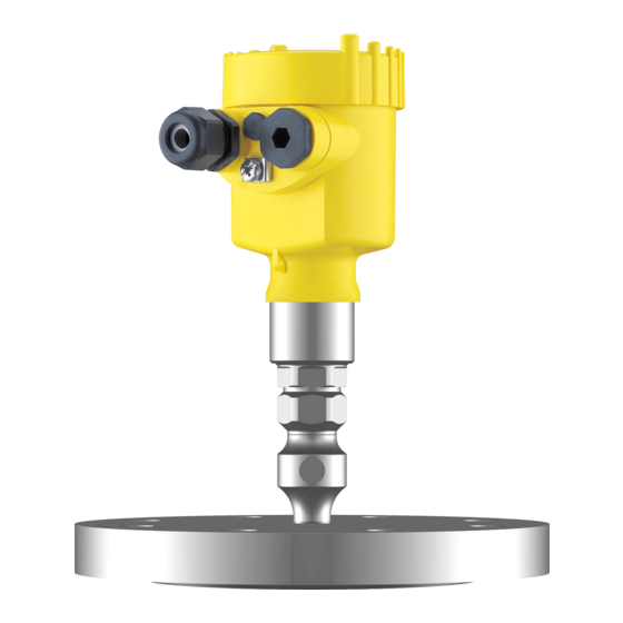
Pressure transmitter with chemical seal
Hide thumbs
Also See for VEGABAR 81:
- Operating instructions manual (96 pages) ,
- Quick setup manual (20 pages) ,
- Product information (16 pages)

Related Manuals for Vega VEGABAR 81


Summary of Contents for Vega VEGABAR 81
-
Page 1: Operating Instructions
Operating Instructions Pressure transmitter with chemical seal VEGABAR 81 4 … 20 mA Document ID: 45025... -
Page 2: Table Of Contents
Connect the PC ......................43 Parameter adjustment ....................43 Saving the parameter adjustment data ................44 Set up with other systems DD adjustment programs ....................45 Field Communicator 375, 475 ..................45 Diagnostics and service VEGABAR 81 • 4 … 20 mA... - Page 3 11.2 Dimensions ........................61 Safety instructions for Ex areas Please note the Ex-specific safety information for installation and op- eration in Ex areas. These safety instructions are part of the operating instructions manual and come with the Ex-approved instruments. Editing status: 2014-02-11 VEGABAR 81 • 4 … 20 mA...
-
Page 4: About This Document
This arrow indicates a single action. Sequence of actions Numbers set in front indicate successive steps in a procedure. Battery disposal This symbol indicates special information about the disposal of bat- teries and accumulators. VEGABAR 81 • 4 … 20 mA... -
Page 5: For Your Safety
During work on and with the device the required personal protective equipment must always be worn. Appropriate use The VEGABAR 81 is a pressure transmitter for process pressure and hydrostatic level measurement. You can find detailed information about the area of application in chapter "Product description". Operational reliability is ensured only if the instrument is properly used according to the specifications in the operating instructions manual as well as possible supplementary instructions. -
Page 6: Namur Recommendations
That is why we have introduced an environment management system with the goal of continuously improving company environmental pro- tection. The environment management system is certified according to DIN EN ISO 14001. Please help us fulfill this obligation by observing the environmental instructions in this manual: • Chapter "Packaging, transport and storage" • Chapter "Disposal" VEGABAR 81 • 4 … 20 mA... -
Page 7: Product Description
Operating instructions and quick setup guide at the time of ship- ment (PDF) • Order-specific sensor data for an electronics exchange (XML) • Test certificate (PDF) - optional Go to www.vega.com, "VEGA Tools" and "Instrument search". Enter the serial number. Alternatively, you can access the data via your smartphone: VEGABAR 81 • 4 … 20 mA... -
Page 8: Principle Of Operation
In this operating instructions manual, the optional instrument features are described. The respective scope of delivery results from the order specification. Principle of operation The VEGABAR 81 is suitable for the measurement of the following Measured variables process variables: •... - Page 9 3 Product description In combination with a slave sensor, VEGABAR 81 is also suitable for Electronic differential pressure electronic differential pressure measurement. You can find detailed information in the operating instructions of the respective slave sensor. Application area VEGABAR 81 is suitable for applications in virtually all industries. It is used for the measurement of the following pressure types.
-
Page 10: Packaging, Transport And Storage
The interface adapter VEGACONNECT enables the connection of communication-capable instruments to the USB interface of a PC. For parameter adjustment of these instruments, the adjustment software PACTware with VEGA-DTM is required. You can find further information in the operating instructions "Interface adapter VEGACONNECT" (Document-ID 32628). VEGABAR 81 • 4 … 20 mA... - Page 11 "Welded socket VEGABAR series 80" (Document-ID 45082). Electronics module The electronics module VEGABAR series 80 is a replacement part for pressure transmitters of VEGABAR series 80. There is a different version available for each type of signal output. You can find further information in the operating instructions "Elec- tronics module VEGABAR series 80" (Document-ID 45054). VEGABAR 81 • 4 … 20 mA...
-
Page 12: Mounting
Higher process temperatures often mean also higher ambient Temperature limits temperatures. Make sure that the upper temperature limits stated in chapter "Technical data" for the environment of the electronics hous- ing and connection cable are not exceeded. VEGABAR 81 • 4 … 20 mA... -
Page 13: Ventilation And Pressure Compensation
Ex-ia version following functions: • Ventilation of the electronics housing • Atmospheric pressure compensation (with relative pressure meas- uring ranges) → Turn the housing so that the filter element points downward after the instrument is installed. This provides better protection against buildup. VEGABAR 81 • 4 … 20 mA... - Page 14 Fig. 6: Position of the filter element - Ex-d version Single chamber housing, aluminium, stainless steel precision casting Double chamber housing, aluminium, stainless steel precision casting Rotatable metal ring Filter element Instruments with absolute pressure have a blind plug mounted instead of the filter element. VEGABAR 81 • 4 … 20 mA...
- Page 15 This provides better protection against buildup. Fig. 8: Position of the filter element - IP 69K version Filter element Instruments with absolute pressure have a blind plug mounted instead of the filter element. VEGABAR 81 • 4 … 20 mA...
-
Page 16: Process Pressure Measurement
Measurement setup in Keep the following in mind when setting up the measuring system: vapours • Connect via a siphon • Do not insulate the siphon • Fill the siphon with water before setup VEGABAR 81 • 4 … 20 mA... - Page 17 < 100 °C on the transmitter is ensured. Measurement setup in Keep the following in mind when setting up the measuring system: liquids • Mount the instrument below the measuring point The effective pressure line is always filled with liquid and gas bubbles can bubble up to the process line. VEGABAR 81 • 4 … 20 mA...
-
Page 18: Level Measurement
• Mount the instrument below the min. level • Do not mount the instrument close to the filling stream or emptying area • Mount the instrument so that it is protected against pressure shocks from the stirrer Fig. 12: Measurement setup for level measurement VEGABAR 81 • 4 … 20 mA... -
Page 19: External Housing
1. Mark the holes according to the following drilling template 2. Fasten wall mounting plate with 4 screws 90 mm (3.54") 70 mm (2.76") 8 mm (0.12") (0.32") Fig. 14: Drilling template - wall mounting plate VEGABAR 81 • 4 … 20 mA... -
Page 20: Connecting To Power Supply
(low impedance). With Ex systems, the grounding is carried out according to the instal- lation regulations. In electroplating and CCP systems (cathodic corrosion protection) it must be taken into account that significant potential differences exist. VEGABAR 81 • 4 … 20 mA... -
Page 21: Connecting
1 cm (0.4 in) of insulation from the ends of the individual wires 5. Insert the cable into the sensor through the cable entry Fig. 15: Connection steps 5 and 6 - Single chamber housing VEGABAR 81 • 4 … 20 mA... -
Page 22: Single Chamber Housing
Electronics and terminal compartment 4...20mA Fig. 16: Electronics and terminal compartment, single chamber housing Voltage supply, signal output For display and adjustment module or interface adapter Ground terminal for connection of the cable screen VEGABAR 81 • 4 … 20 mA... -
Page 23: Housing Ip 66/Ip 68 (1 Bar)
(+) and blue (-) to power supply or to the processing system Shielding External housing with version IP 68 (25 bar) Overview Fig. 18: VEGABAR 81 in IP 68 version 25 bar with axial cable outlet, external housing Transmitter Connection cable External housing VEGABAR 81 •... -
Page 24: Power Supply
Cable gland for voltage supply Cable gland for connection cable, transmitter Terminal compartment, housing socket 1 2 3 4 Fig. 20: Connection of the sensor in the housing base Yellow White Black Shielding Breather capillaries VEGABAR 81 • 4 … 20 mA... -
Page 25: Switch-On Phase
The output signal jumps to the set fault current Then the actual measured value is outputted to the signal cable. The value takes already carried out settings, e.g. default setting into ac- count. VEGABAR 81 • 4 … 20 mA... -
Page 26: Set Up With The Display And Adjustment Module
Fig. 22: Installing the display and adjustment module in the electronics compart- ment of the single chamber housing Note: If you intend to retrofit the instrument with a display and adjustment module for continuous measured value indication, a higher cover with an inspection glass is required. VEGABAR 81 • 4 … 20 mA... -
Page 27: Adjustment System
[OK] will not be saved. Parameter adjustment - Quick setup To quickly and easily adapt the sensor to the application, select the menu item "Quick setup" in the start graphic on the display and adjustment module. VEGABAR 81 • 4 … 20 mA... - Page 28 4. Position correction urement In this menu item you compensate the influence of the installation position of the instrument (offset) on the measured value. 5. Max. adjustment In this menu item you carry out the max. adjustment for level Enter the percentage value and the corresponding value for the max. level. VEGABAR 81 • 4 … 20 mA...
-
Page 29: Parameter Adjustment - Extended Adjustment
The procedure is described below. The following submenu points are available: The submenu points described below. Setup - Measurement In the menu item "Sensor TAG" you edit a twelve digit measurement loop name loop designation label. VEGABAR 81 • 4 … 20 mA... - Page 30 VEGABAR 81 can be used for process pressure and level measure- ment. Default setting is process pressure measurement. The mode can be changed in this adjustment menu. The VEGABAR 81 in conjunction with a slave sensor can be used for flow, differential pressure, density and interface measurement. The default setting is differential pressure measurement. Switchover is carried out in the adjustment menu.
- Page 31 Setup - Adjustment VEGABAR 81 always measures pressure independently of the pro- cess variable selected in the menu item "Application". To output the selected process variable correctly, an allocation to 0 % and 100 % of the output signal must be carried out (adjustment).
- Page 32 Now select with [->] the menu item "zero adjustment" and confirm with [OK]. 2. Edit the mbar value with [OK] and set the cursor to the requested position with [->]. 3. Set the requested mbar value with [+] and store with [OK]. VEGABAR 81 • 4 … 20 mA...
- Page 33 3. Set the requested percentage value (e.g. 10 %) with [+] and save with [OK]. The cursor jumps now to the pressure value. 4. Enter the pressure value corresponding to the min. level (e.g. 0 mbar). VEGABAR 81 • 4 … 20 mA...
- Page 34 They represent the correlation between the level per- centage and vessel volume. The linearization applies to the measured value indication and the current output. Caution: Note the following, if the respective sensor is used as part of an over- fill protection system according to WHG: If a linearization curve is selected, the measuring signal is no longer necessarily linear to the filling height. This must be considered by the VEGABAR 81 • 4 … 20 mA...
- Page 35 With active PIN, adjustment via PACTware/DTM as well as other systems is also blocked. You can change the PIN number under "Additional adjustments - PIN". Display - Language This menu item enables the setting of the requested national lan- guage. VEGABAR 81 • 4 … 20 mA...
- Page 36 • Polish • Czech • Turkish In the delivery status, the VEGABAR 81 is set to the ordered national language. Display - Displayed value In this menu item you can define the indication of the measured 1 and 2 values on the display. The default setting for the display value is "Lin. percent".
- Page 37 "Setup/ Lock/release adjustment ". In delivery status, the PIN is "0000". Additional adjustments - In this menu item, you adjust the internal clock of the sensor. There is Date Time no adjustment to summer/winter time. VEGABAR 81 • 4 … 20 mA...
- Page 38 (with nominal measuring rang- es ≥1 bar) Temperature unit °C Position correc- 0.00 bar tion Adjustment Zero/Min. adjust- 0.00 bar ment 0.00 % Span/Max. adjust- Nominal measuring range in bar ment 100.00 % Damping Integration time 0.0 s VEGABAR 81 • 4 … 20 mA...
- Page 39 Current output - adjustment 0 … 100 % correspond to 4 … 20 mA Additional adjustments - The instrument settings are copied with this function. The following Copy instrument settings functions are available: VEGABAR 81 • 4 … 20 mA...
- Page 40 Setup - Scaling (2) In menu item "Scaling (2)" you define the scaling format on the display and the scaling of the measured level value for 0 % and 100 %. VEGABAR 81 • 4 … 20 mA...
-
Page 41: Saving The Parameter Adjustment Data
Saving the parameter adjustment data We recommended noting the adjusted data, e.g. in this operating instructions manual, and archiving them afterwards. They are thus available for multiple use or service purposes. VEGABAR 81 • 4 … 20 mA... - Page 42 If it is necessary to exchange a sensor, the display and adjustment module is inserted into the replacement instrument and the data are likewise written into the sensor via the menu item "Copy sensor data". VEGABAR 81 • 4 … 20 mA...
-
Page 43: Setup With Pactware
Further setup steps are described in the operating instructions manu- al "DTM Collection/PACTware" attached to each DTM Collection and which can also be downloaded from the Internet. Detailed descrip- tions are available in the online help of PACTware and the DTMs. VEGABAR 81 • 4 … 20 mA... -
Page 44: Saving The Parameter Adjustment Data
The standard version is available as a download under www.vega.com/downloads and "Software". The full version is avail- able on CD from the agency serving you. Saving the parameter adjustment data We recommend documenting or saving the parameter adjustment data via PACTware. -
Page 45: Set Up With Other Systems
This software is updated via the Internet and new EDDs are automatically taken over into the device catalogue of this software after they are released by the manufacturer. They can then be transferred to a Field Communicator. VEGABAR 81 • 4 … 20 mA... -
Page 46: Diagnostics And Service
Reaction after fault recti- Depending on the reason for the fault and the measures taken, the fication steps described in chapter "Setup" must be carried out again or must be checked for plausibility and completeness. VEGABAR 81 • 4 … 20 mA... -
Page 47: Exchanging The Electronics Module
Should these measures not be successful, please call in urgent cases 24 hour service hotline the VEGA service hotline under the phone no. +49 1805 858550. The hotline is also available outside normal working hours, seven days a week around the clock. -
Page 48: Software Update
9 Diagnostics and service Fig. 27: VEGABAR 81 in IP 68 version, 25 bar and lateral cable outlet, external housing Process assembly Plug connector Fixing screw Cable assembly Connection cable External housing 3. Loosen the plug connector 4. Mount the new process assembly on the measuring point 5. -
Page 49: How To Proceed If A Repair Is Needed
Clean the instrument and pack it damage-proof • Attach the completed form and, if need be, also a safety data sheet outside on the packaging • Please contact the agency serving you to get the address for the return shipment. You can find the agency on our home page www.vega.com. VEGABAR 81 • 4 … 20 mA... -
Page 50: Dismounting
Pass the instrument directly on to a spe- cialised recycling company and do not use the municipal collecting points. These may be used only for privately used products according to the WEEE directive. VEGABAR 81 • 4 … 20 mA... -
Page 51: Supplement
0.8 … 8 kg (1.764 … 17.64 lbs), depending on process fitting and housing Torques Max. torque for NPT cable glands and Conduit tubes Ʋ Plastic housing 10 Nm (7.376 lbf ft) Ʋ Aluminium/Stainless steel housing 50 Nm (36.88 lbf ft) VEGABAR 81 • 4 … 20 mA... - Page 52 Nominal measuring ranges and overload capacity in psi The specifications are only an overview and refer to the measuring cell. Limitations due to the material and version of the process fitting as well as the selected pressure type are possible. The specifications on the nameplate apply. Nominal range Overload capacity, max. Overload capacity, min. pres- pressure sure Gauge pressure 0 … +5 psig +25 psig -14.5 psig 0 … +15 psig +75 psig -14.5 psig VEGABAR 81 • 4 … 20 mA...
- Page 53 120 % of the nominal range Recommended max. turn down 20 : 1 (no limitation) Switch-on phase Run-up time approx. 15 s Starting current Ʋ for 5 ms after switching on ≤ 10 mA Ʋ for run-up time ≤ 3.6 mA VEGABAR 81 • 4 … 20 mA...
- Page 54 10 % Fig. 28: Sudden change of the process variable. t : dead time; t : rise time; t : jump response time Process variable Output signal The indication values can be assigned individually VEGABAR 81 • 4 … 20 mA...
- Page 55 Step response time Ʋ VEGABAR 81 ≤ 80 ms (ti: 0 s, 10 … 90 %) Ʋ VEGABAR 81 - IP 68 (25 bar) ≤ 200 ms (ti: 0 s, 10 … 90 %) To this amounts the reaction time of the isolatng system. This time varies from values < 1 s with compact chemical seals to several seconds with capillary systems.
- Page 56 Ʋ Flange 3" 150 lbs RF, ANSI B16.5 with 1.34 mbar/10 K extension 2 " Temperature coefficient of a cooling ele- 0.1 … 1.5 mbar/10 K ment, depending on the diaphragm-ø Temperature coefficient of a 1 m 0.1 … 15 mbar/10 K long capillary line, depending on the diaphragm-ø VEGABAR 81 • 4 … 20 mA...
-
Page 57: Ambient Conditions
-40 … +70 °C (- No vacuum -40 … +60 °C (- 40 … +158 °F) 40 … +140 °F) Depending on which chemical seal is used, the values can also be higher. VEGABAR 81 • 4 … 20 mA... - Page 58 Ʋ Standard length 5 m (16.4 ft) Ʋ Max. length 180 m (590.6 ft) Ʋ Min. bending radius 25 mm (0.984 in) with 25 °C (77 °F) Ʋ Diameter approx. 8 mm (0.315 in) VEGABAR 81 • 4 … 20 mA...
- Page 59 Ʋ unassembled IP 20 Ʋ mounted into the housing without IP 40 cover Materials Ʋ Housing Ʋ Inspection window Polyester foil Measurement electronics temerature Resolution 1 °C (1.8 °F) Accuracy ±1 °C (1.8 °F) VEGABAR 81 • 4 … 20 mA...
- Page 60 NEMA 4X/6P casting IP 68 (1 bar) NEMA 4X Double chamber IP 66/IP 67 NEMA 4X IP 66/IP 68 (0.2 bar) NEMA 4X Stainless steel Transmitter for external IP 68 (25 bar) housing Overvoltage category Protection class VEGABAR 81 • 4 … 20 mA...
-
Page 61: Dimensions
Instruments with approvals can have different technical data depending on the version. For that reason the associated approval documents of these instruments have to be carefully noted. They are part of the delivery or can be downloaded under www.vega.com, "VEGA Tools" and "Instrument search" as well as under www.vega.com/downloads and "Approvals". - Page 62 (4.33" x 3.54") 41,6 mm (1.64") ~ 66 mm (2.60") 110 mm x 90 mm (4.33" x 3.54") Fig. 31: IP 68 version with external housing - plastic version Lateral cable outlet Axial cable outlet VEGABAR 81 • 4 … 20 mA...
- Page 63 ø 39 mm ø 60 mm (1.54") (2.36") Fig. 32: VEGABAR 81, threaded fitting GE G½ (ISO 228-1), >105 °C with temperature adapter GK G¾ (DIN 3852-E) GL G1 (DIN 3852-E) GN G1½ (DIN 3852-A) VEGABAR 81 • 4 … 20 mA...
- Page 64 4.09" 0.39" RD44x " 4.09" 0.79" Fig. 33: VEGABAR 81, tube isolating diaphragm Tube isolating diaphragm for mounting between flanges Tube isolating diaphragm according to DIN 11851 Tube isolating diaphragm according to DIN 11864-1 VEGABAR 81 • 4 … 20 mA...
- Page 65 3" 24,3 152,4 4 x ø19 152,5 3" 24,3 152,4 Fig. 34: VEGABAR 81, flange connection, dimensions in mm Flange connection according to DIN 2501 Flange connection according to ANSI B16.5 Diaphragm diameter VEGABAR 81 • 4 … 20 mA...
- Page 66 4 x ø0.75" 6" 2.99" 2.84" 3" 7.48" 0.96" 6" 5" 0.08" Fig. 35: VEGABAR 81, flange connection, dimensions in inch Flange connection according to DIN 2501 Flange connection according to ANSI B16.5 Diaphragm diameter VEGABAR 81 • 4 … 20 mA...
- Page 67 0.79" 5.43" 0.71" 3.5" 16..100 6.3" 0.79" 5.43" 3.5" Fig. 36: VEGABAR 81, flange and cell isolating diaphragm with capillary line Flange isolating diaphragm with capillary line Cell isolating diaphragm with capillary line VEGABAR 81 • 4 … 20 mA...
- Page 68 Les lignes de produits VEGA sont globalement protégées par des droits de propriété intellec- tuelle. Pour plus d'informations, on pourra se référer au site www.vega.com. VEGA lineas de productos están protegidas por los derechos en el campo de la propiedad indus- trial. Para mayor información revise la pagina web www.vega.com.
- Page 69 Electronics and terminal compartment, single chamber housing 22, 25 Fault rectification 46 Gas-tight leadthrough (Second Line of Defense) Grounding 20 Level measurement 18 Linearization 34 Maintenance 46 Measurement setup – In gases 16 – In liquids 17 VEGABAR 81 • 4 … 20 mA...
- Page 70 Notes VEGABAR 81 • 4 … 20 mA...
- Page 71 Notes VEGABAR 81 • 4 … 20 mA...
- Page 72 Subject to change without prior notice © VEGA Grieshaber KG, Schiltach/Germany 2014 VEGA Grieshaber KG Phone +49 7836 50-0 Am Hohenstein 113...
Need help?
Do you have a question about the VEGABAR 81 and is the answer not in the manual?
Questions and answers