Vega VEGABAR 83 Operating Instructions Manual
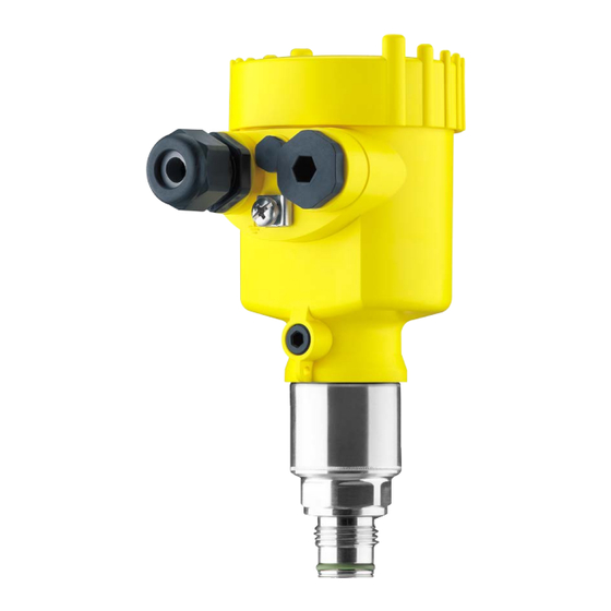
Pressure transmitter with metallic measuring cell, modbus and levelmaster protocol
Hide thumbs
Also See for VEGABAR 83:
- Operating instructions manual (108 pages) ,
- Quick setup manual (24 pages) ,
- Product information (16 pages)

Related Manuals for Vega VEGABAR 83


Summary of Contents for Vega VEGABAR 83
-
Page 1: Operating Instructions
Operating Instructions Pressure transmitter with metallic measuring cell VEGABAR 83 Modbus and Levelmaster protocol Document ID: 46295... -
Page 2: Table Of Contents
Connect the PC ......................43 Parameter adjustment ....................44 Saving the parameter adjustment data ................46 Diagnosis, asset management and service Maintenance ........................47 Diagnosis memory ......................47 Asset Management function ................... 47 Rectify faults ........................51 VEGABAR 83 • Modbus and Levelmaster protocol... - Page 3 10.7 Dimensions ........................82 Safety instructions for Ex areas Please note the Ex-specific safety information for installation and op- eration in Ex areas. These safety instructions are part of the operating instructions manual and come with the Ex-approved instruments. Editing status: 2013-10-30 VEGABAR 83 • Modbus and Levelmaster protocol...
-
Page 4: About This Document
This arrow indicates a single action. Sequence of actions Numbers set in front indicate successive steps in a procedure. Battery disposal This symbol indicates special information about the disposal of bat- teries and accumulators. VEGABAR 83 • Modbus and Levelmaster protocol... -
Page 5: For Your Safety
During work on and with the device the required personal protective equipment must always be worn. Appropriate use The VEGABAR 83 is a pressure transmitter for process pressure and hydrostatic level measurement. You can find detailed information on the application range in chapter "Product description". Operational reliability is ensured only if the instrument is properly used according to the specifications in the operating instructions manual as well as possible supplementary instructions. -
Page 6: Measuring Range - Permissible Process Pressure
That is why we have introduced an environment management system with the goal of continuously improving company environmental pro- tection. The environment management system is certified according to DIN EN ISO 14001. Please help us fulfill this obligation by observing the environmental instructions in this manual: • Chapter "Packaging, transport and storage" • Chapter "Disposal" VEGABAR 83 • Modbus and Levelmaster protocol... -
Page 7: Product Description
Go to www.vega.com, "VEGA Tools" and "Serial number search". As an alternative, you can find the data via your Smartphone: • Download the smartphone app "VEGA Tools" from the "Apple App Store" or the "Google Play Store" • Scan the Data Matrix code on the type label of the instrument or •... -
Page 8: Principle Of Operation
• Process pressure • Level Fig. 2: Process pressure measurement VEGABAR 83 Electronic differential In combination with a slave sensor, VEGABAR 83 is also suitable for pressure electronic differential pressure measurement. You can find detailed information in the operating instructions of the respective slave sensor. Application area VEGABAR 83 is suitable for applications in virtually all industries. It is used for the measurement of the following pressure types. - Page 9 • Vacuum Measured products Measured products are gases, vapours and liquids. VEGABAR 83 is especially suitable for applications with higher tem- peratures and high pressures. Measuring system The process pressure acts on the sensor element via the process diaphragm and an internal transmission liquid. The process pressure causes a resistance change which is converted into a corresponding output signal and outputted as measured value.
-
Page 10: Packaging, Transport And Storage
Protected against solar radiation • Avoiding mechanical shock and vibration • Storage and transport Storage and transport temperature see chapter "Supplement - temperature Technical data - Ambient conditions" • Relative humidity 20 … 85 % VEGABAR 83 • Modbus and Levelmaster protocol... -
Page 11: Accessories And Replacement Parts
Slave sensors of VEGABAR series 80 enable in conjunction with VEGABAR 83 an electronic differential pressure measurement. You can find further information in the operating instructions of the respective slave sensor. VEGADIS 81 The VEGADIS 81 is an external display and adjustment unit for VEGA plics sensors. ® For sensors with double chamber housing the interface adapter "DIS- ADAPT"... - Page 12 You can find further information in the operating instructions "Elec- tronics module VEGABAR series 80" (Document-ID 45054). Supplementary electron- The supplementary electronics is a replacement part for sensors with ics Modbus signal output Modbus. You can find further information in the operating instructions "Supple- mentary electronics Modbus" (Document-ID 41864). VEGABAR 83 • Modbus and Levelmaster protocol...
-
Page 13: Mounting
Higher process temperatures often mean also higher ambient temperatures. Make sure that the upper temperature limits stated in chapter "Technical data" for the environment of the electronics hous- ing and connection cable are not exceeded. VEGABAR 83 • Modbus and Levelmaster protocol... -
Page 14: Ventilation And Pressure Compensation
The following paragraphs describe how the filter element is arranged in the different instrument versions. The filter element is mounted into the electronics housing. It has the Instruments in non-Ex, Ex-ia and Ex-d-ia version following functions: • Ventilation electronics housing • Atmospheric pressure compensation (with relative pressure meas- uring ranges) VEGABAR 83 • Modbus and Levelmaster protocol... - Page 15 • Atmospheric pressure compensation (with relative pressure meas- uring ranges) Turn the metal ring in such a way that the filter element points down- ward after installtion of the instrument. This provides better protection against buildup. VEGABAR 83 • Modbus and Levelmaster protocol...
-
Page 16: Process Pressure Measurement
Process pressure measurement Measurement setup in Keep the following in mind when setting up the measuring system: gases • Mount the instrument above the measuring point VEGABAR 83 • Modbus and Levelmaster protocol... - Page 17 Measurement setup in Keep the following in mind when setting up the measuring system: vapours • Connect via a siphon • Do not insulate the siphon • Fill the siphon with water before setup VEGABAR 83 • Modbus and Levelmaster protocol...
- Page 18 < 100 °C on the transmitter is ensured. Measurement setup in Keep the following in mind when setting up the measuring system: liquids • Mount the instrument below the measuring point The effective pressure line is always filled with liquid and gas bubbles can bubble up to the process line. VEGABAR 83 • Modbus and Levelmaster protocol...
-
Page 19: Level Measurement
• Mount the instrument below the min. level • Do not mount the instrument close to the filling stream or emptying area • Mount the instrument so that it is protected against pressure shocks from the stirrer Fig. 12: Measurement setup for level measurement VEGABAR 83 • Modbus and Levelmaster protocol... -
Page 20: External Housing
1. Mark the holes according to the following drilling template 2. Fasten wall mounting plate with 4 screws 90 mm (3.54") 70 mm (2.76") 8 mm (0.12") (0.32") Fig. 14: Drilling template - wall mounting plate VEGABAR 83 • Modbus and Levelmaster protocol... -
Page 21: Connecting To Power Supply And Bus System
(e.g. 1 nF, 1500 V). The low frequency potential equalisation currents are thus suppressed, but the protective effect against high frequency interference signals remains. VEGABAR 83 • Modbus and Levelmaster protocol... -
Page 22: Connection
When the screwdriver is released, the terminal closes again. 6. Check the hold of the wires in the terminals by lightly pulling on them VEGABAR 83 • Modbus and Levelmaster protocol... -
Page 23: Wiring Plan
Fig. 16: Position of connection compartment (Modbus electronics) and electron- ics compartment (sensor electronics) Connection compartment Electronics compartment Electronics compartment 4...20mA Fig. 17: Electronics compartment, double chamber housing Internal connection to the connection compartment For display and adjustment module or interface adapter VEGABAR 83 • Modbus and Levelmaster protocol... -
Page 24: External Housing With Version Ip 68 (25 Bar)
Modbus-Signal D1 Function ground with installa- tion according to CSA External housing with version IP 68 (25 bar) Overview Fig. 19: VEGABAR 83 in IP 68 version 25 bar with axial cable outlet, external housing Transmitter Connection cable External housing... -
Page 25: Power Supply
Cable gland for voltage supply Cable gland for connection cable, transmitter Terminal compartment, housing socket 1 2 3 4 Fig. 21: Connection of the sensor in the housing base Yellow White Black Shielding Breather capillaries VEGABAR 83 • Modbus and Levelmaster protocol... -
Page 26: Switch-On Phase
The output signal jumps to the set fault current Then the actual measured value is outputted to the signal cable. The value takes already carried out settings, e.g. default setting into ac- count. VEGABAR 83 • Modbus and Levelmaster protocol... -
Page 27: Set Up With The Display And Adjustment Module
Fig. 23: Insertion of the display and adjustment module with single chamber housing Note: If you intend to retrofit the instrument with a display and adjustment module for continuous measured value indication, a higher cover with an inspection glass is required. VEGABAR 83 • Modbus and Levelmaster protocol... -
Page 28: Adjustment System
[OK] will not be saved. Parameter adjustment - Quick setup To quickly and easily adapt the sensor to the application, select the menu item "Quick setup" in the start graphic on the display and adjustment module. VEGABAR 83 • Modbus and Levelmaster protocol... - Page 29 4. Position correction urement In this menu item you compensate the influence of the installation position of the instrument (offset) to the measured value. 5. Max. adjustment In this menu item you carry out the max. adjustment for level Enter the percentage value and the corresponding value for the max. level. VEGABAR 83 • Modbus and Levelmaster protocol...
-
Page 30: Parameter Adjustment - Extended Adjustment
In digital systems and in the documentation of larger plants, a singular desig- nation must be entered for exact identification of individual measuring points. The available digits comprise: • Letters from A … Z • Numbers from 0 … 9 VEGABAR 83 • Modbus and Levelmaster protocol... - Page 31 VEGABAR 83 can be used for process pressure and level measure- ment. Default setting is process pressure measurement. The mode can be changed in this adjustment menu. The VEGABAR 83 in conjunction with a slave sensor can be used for flow, differential pressure, density and interface measurement. The default setting is differential pressure measurement. Switchover is carried out in the adjustment menu.
- Page 32 20 % of the nominal measuring range, then no position correction is possible. VEGABAR 83 always measures pressure independently of the pro- Setup - Adjustment cess variable selected in the menu item "Application". To output the selected process variable correctly, an allocation to 0 % and 100 % of the output signal must be carried out (adjustment).
- Page 33 Now select with [->] the menu item "zero adjustment" and confirm with [OK]. 2. Edit the mbar value with [OK] and set the cursor to the requested position with [->]. 3. Set the requested mbar value with [+] and store with [OK]. VEGABAR 83 • Modbus and Levelmaster protocol...
- Page 34 3. Set the requested percentage value (e.g. 10 %) with [+] and save with [OK]. The cursor jumps now to the pressure value. 4. Enter the pressure value corresponding to the min. level (e.g. 0 mbar). VEGABAR 83 • Modbus and Levelmaster protocol...
- Page 35 They represent the correlation between the level per- centage and vessel volume. The linearization applies to the measured value indication and the current output. Caution: Note the following, if the respective sensor is used as part of an over- fill protection system according to WHG: If a linearization curve is selected, the measuring signal is no longer necessarily linear to the filling height. This must be considered by the VEGABAR 83 • Modbus and Levelmaster protocol...
- Page 36 Display - Language This menu item enables the setting of the requested national lan- guage. The following languages are available: • German • English • French • Spanish • Russian • Italian • Dutch VEGABAR 83 • Modbus and Levelmaster protocol...
- Page 37 • Polish • Czech • Turkish In the delivery status, the VEGABAR 83 is set to the ordered national language. Display - Displayed value In this menu item you can define the indication of the measured 1 and 2 values on the display. The default setting for the display value is "Lin. percent".
- Page 38 Additional adjustments With a reset, certain parameter adjustments carried out by the user - Reset are reset. The following reset functions are available: Delivery status: Restoring the parameter settings at the time of shipment from the factory incl. the order-specific settings. A user-pro- VEGABAR 83 • Modbus and Levelmaster protocol...
- Page 39 Reaction when malfunction occurs ≤ 3.6 mA Current output - 3.8 mA Min./Max. 20.5 mA Lock adjustment Released Reset - Display Menu item Default value Menu language Order-specific Displayed value 1 Current output in % VEGABAR 83 • Modbus and Levelmaster protocol...
- Page 40 The following data or settings for adjustment of the display and ad- justment module are saved: • All data of the menu "Setup" and "Display" • In the menu "Additional adjustments" the items "Reset, Date/Time" • The user-programmable linearization curve VEGABAR 83 • Modbus and Levelmaster protocol...
- Page 41 PC. Info - Sensor character- In this menu item, the features of the sensor such as approval, pro- istics cess fitting, seal, measuring range, electronics, housing and others are displayed. VEGABAR 83 • Modbus and Levelmaster protocol...
-
Page 42: Saving The Parameter Adjustment Data
If it is necessary to exchange a sensor, the display and adjustment module is inserted into the replacement instrument and the data are likewise written into the sensor via the menu item "Copy sensor data". VEGABAR 83 • Modbus and Levelmaster protocol... -
Page 43: Setting Up Sensor And Modbus Interface With Pactware
Interface adapter VEGACONNECT Sensor To the Modbus electron- The connection of the PC to the Modbus electronics is carried out via a USB cable. Scope of the parameter adjustment: • Sensor electronics • Modbus electronics VEGABAR 83 • Modbus and Levelmaster protocol... -
Page 44: Parameter Adjustment
FDT standard are required. The up-to-date PACTware version as well as all available DTMs are compiled in a DTM Collec- tion. The DTMs can also be integrated into other frame applications according to FDT standard. VEGABAR 83 • Modbus and Levelmaster protocol... - Page 45 The standard version is available as a download under www.vega.com/downloads and "Software". The full version is avail- able on CD from the agency serving you. VEGABAR 83 • Modbus and Levelmaster protocol...
-
Page 46: Saving The Parameter Adjustment Data
7 Setting up sensor and Modbus interface with PACTware Saving the parameter adjustment data We recommend documenting or saving the parameter adjustment data via PACTware. That way the data are available for multiple use or service purposes. VEGABAR 83 • Modbus and Levelmaster protocol... -
Page 47: Diagnosis, Asset Management And Service
The data are read out via a PC with PACTware/DTM or the control system with EDD. Asset Management function The instrument features self-monitoring and diagnostics according to NE 107 and VDI/VDE 2650. In addition to the status messages in VEGABAR 83 • Modbus and Levelmaster protocol... - Page 48 This status message is inactive by default. It can be activated by the user via PACTware/DTM or EDD. Failure The following table shows the error codes in the status message "Failure" and gives information on the reason and rectification. Keep in mind that some information is only valid with four-wire instruments. VEGABAR 83 • Modbus and Levelmaster protocol...
- Page 49 – Send instrument for repair Error in the – Error in the EEPROM calibration F261 – Error during setup – Repeat setup – Error when carrying out a – Repeat reset Error in the reset configuration VEGABAR 83 • Modbus and Levelmaster protocol...
- Page 50 "Maintenance" and provides information on causes as well as corrective measures. Code Cause Rectification Text mes- sage M500 – Stored delivery status is – Send instrument for repair incorrect Error in the delivery sta- VEGABAR 83 • Modbus and Levelmaster protocol...
-
Page 51: Rectify Faults
24 hour service hotline Should these measures not be successful, please call in urgent cases the VEGA service hotline under the phone no. +49 1805 858550. The hotline is also available outside normal working hours, seven days a week around the clock. -
Page 52: Calculation Of Total Deviation (According To Din 16086)
Pressure measurement in the pipeline 8 bar (800 KPa) Practical example Product temperature up to 50 °C VEGABAR 83 with measuring range 10 bar, deviation < 0.075 % Calculation of the turn down: TD = 10 bar/8 bar, TD = 1.25 Calculation 1. -
Page 53: Exchanging The Electronics Module
Proceed as follows when carrying out the exchange: 1. Losen the fixing screw with the hexagon socket wrench 2. Carefully detach the cable assembly from the process assembly Fig. 31: VEGABAR 83 in IP 68 version, 25 bar and lateral cable outlet, external housing Process assembly Plug connector... -
Page 54: Software Update
The electronics module with serial number includes order- specific data such as factory setting, seal material etc. These are not included in the electronics module without serial number. The serial number is stated on the type label of VEGABAR 83 or on the delivery note. You can find detailed information on the electronics exchange in the booklet "Operating instructions for electronics module VEGABAR... -
Page 55: Dismounting
Pass the instrument directly on to a spe- cialised recycling company and do not use the municipal collecting points. These may be used only for privately used products according to the WEEE directive. VEGABAR 83 • Modbus and Levelmaster protocol... -
Page 56: Supplement
Synthetic oil for measuring ranges up to 16 bar, FDA listed for the food processing industry. For measuring ranges up to 25 bar dry measuring cell. Halocarbon oil: Generally in oxygen applications, not with vacuum measuring ranges, not with absolute meas- uring ranges < 1 bar VEGABAR 83 • Modbus and Levelmaster protocol... - Page 57 -0.2 … +0.2 bar/-20 … +20 kPa +2 bar/+200 kPa -1 bar/-100 kPa -0.5 … +0.5 bar/-50 … +50 kPa +5 bar/+500 kPa -1 bar/-100 kPa Values less than -1 bar cannot be set. VEGABAR 83 • Modbus and Levelmaster protocol...
- Page 58 0 psi 0 … +30 psi +120 psi 0 psi 0 … +150 psi +1200 psi 0 psi 0 … +300 psi +1200 psi 0 psi Input variable - Ceramic/metal measuring cell Adjustment VEGABAR 83 • Modbus and Levelmaster protocol...
- Page 59 0 bar abs. 0 … 25 bar/0 … 2500 kPa 130 bar/13000 kPa 0 bar abs. Nominal measuring ranges and overload capacity in psi The specifications are only an overview and refer to the measuring cell. Limitations due to the ma- terial and version of the process fitting are possible. The specifications on the nameplate apply. Values less than -1 bar cannot be set. VEGABAR 83 • Modbus and Levelmaster protocol...
- Page 60 V1.02 Ʋ Data protocols Modbus RTU, Modbus ASCII, Levelmaster Max. transmission rate 19.2 Kbit/s Dynamic behaviour output Run-up time approx. 10 s Dynamic characteristics, depending on medium, temperature and, if applicable, chemical seal VEGABAR 83 • Modbus and Levelmaster protocol...
- Page 61 < 0.015 % x TD 0.1 % < 0.1 % < 0.02 % x TD 0.2 % < 0.2 % < 0.04 % x TD Influence of the product or ambient temperature Thermal change zero signal and output span VEGABAR 83 • Modbus and Levelmaster protocol...
- Page 62 -3 … 3 psig < {0.15 % + 0.4 x < {0.15 % + 0.6 x (0.5+0.5 x TD)} (0.5+0.5 x TD)} 0 … 0.4 bar/0 … 40 kPa 0 … 6 psig VEGABAR 83 • Modbus and Levelmaster protocol...
-
Page 63: Ambient Conditions
High temperature -12 … +180 °C (+10 … +356 °F) High temperature, screen sheet -12 … +200 °C (+10 … +392 °F) Mechanical stress, depending on the instrument version Vibration resistance 4 g at 5 … 200 Hz according to EN 60068-2-6 (vibration with resonance) VEGABAR 83 • Modbus and Levelmaster protocol... - Page 64 0.5 mm² (AWG 20) Ʋ Wire resistance < 0.036 Ω/m (0.011 Ω/ft) Ʋ Standard length 5 m (16.40 ft) Ʋ Max. length 180 m (590.5 ft) Ʋ Min. bending radius at 25 °C/77 °F 25 mm (0.985 in) VEGABAR 83 • Modbus and Levelmaster protocol...
- Page 65 Configuration, connection cable 4-wire, screened Cable length max. 25 m Integrated clock Date format Day.Month.Year Time format 12 h/24 h Time zone Ex factory Depending on the version M12 x 1, according to ISO 4400, Harting, 7/8" FF. VEGABAR 83 • Modbus and Levelmaster protocol...
- Page 66 Instruments with approvals can have different technical data depending on the version. For that reason the associated approval documents of these instruments must be carefully noted. They are part of the delivery or can be downloaded under www.vega.com and "VEGA Tools" as well as under "Downloads" and "Approvals". VEGABAR 83 • Modbus and Levelmaster protocol...
-
Page 67: Basics Modbus
Fig. 33: Bus architecture Modbus Connection resistor Bus participant Voltage supply Protocol description The VEGABAR 83 is suitable for connection to the following RTUs with Modbus RTU or ASCII protocol. Protocol ABB Totalflow Modbus RTU, ASCII Bristol ControlWaveMicro Modbus RTU, ASCII... -
Page 68: Modbus Register
(4 bytes) according to IEEE 754 are transmitted with individually selectable order of the data bytes (byte transmission order). This "Byte transmission order" is determined in the parameter "Format Code". Hence the RTU knows the registers of the VEGABAR 83 which must be contacted for the variables and status information. - Page 69 Primary Variable in Byte Order ABCD (Big Endian) 2004 DWord Secondary Variable in Byte Order ABCD (Big Endian) 2006 DWord Third Variable in Byte Order ABCD (Big Endian) 2008 DWord Quarternary Variable in Byte Order ABCD (Big En- dian) VEGABAR 83 • Modbus and Levelmaster protocol...
-
Page 70: Modbus Rtu Commands
FC3 Read Holding Register With this command, any number (1-127) of holding registers can be read out. The start register, from which the readout should start, and the number of registers are transmitted. VEGABAR 83 • Modbus and Levelmaster protocol... - Page 71 Length Code/Data Function Code 1 Byte 0x06 Start Address 2 Bytes 0x0000 to 0xFFFF Number of Registers 2 Bytes Data Response: Parameter Length Code/Data Function Code 1 Byte 0x04 Start Address 2 Bytes VEGABAR 83 • Modbus and Levelmaster protocol...
- Page 72 Register Value 2 Bytes 0x0001 to 0x007B Byte Number 1 Byte Register Value N*2 Bytes Data Response: Parameter Length Code/Data Function Code 1 Byte 0x10 Sub Function Code 2 Bytes 0x0000 to 0xFFFF VEGABAR 83 • Modbus and Levelmaster protocol...
- Page 73 1 Byte Object ID number Number of Objects 1 Byte List of Object ID 1 Byte List of Object length 1 Byte List of Object value 1 Byte Depending on the Object ID VEGABAR 83 • Modbus and Levelmaster protocol...
-
Page 74: Levelmaster Commands
10 Supplement 10.5 Levelmaster commands The VEGABAR 83 is also suitable for connection to the following RTUs with Levelmaster protocol. The Levelmaster protocol is often called "Siemens" "Tank protocol". Protocol ABB Totalflow Levelmaster Kimray DACC 2000/3000 Levelmaster Thermo Electron Autopilot Levelmaster... - Page 75 6 characters ASCII UuuNnn Response: Parameter Length Code/Data Assign Unit Number 6 characters ASCII UuuNOK uu = new Address Set number of Floats Request: Parameter Length Code/Data Set number of Floats 5 characters ASCII UuuFn VEGABAR 83 • Modbus and Levelmaster protocol...
- Page 76 = 127 ms Response: Parameter Length Code/Data Set Receive to Transmit Delay 6 characters ASCII UuuROK Report Number of Floats Request: Parameter Length Code/Data Set Receive to Transmit Delay 4 characters ASCII UuuF VEGABAR 83 • Modbus and Levelmaster protocol...
-
Page 77: Error Codes
= milliseconds (50 up to 250), default = 127 ms Error codes Error Code Name EE-Error Error While Storing Data in EEPROM FR-Error Erorr in Frame (too short, too long, wrong data) LV-Error Value out of limits VEGABAR 83 • Modbus and Levelmaster protocol... -
Page 78: Configuration Of Typical Modbus Hosts
10 Supplement 10.6 Configuration of typical Modbus hosts Fisher ROC 809 Wiring plan (Rx/Tx -) (Rx/Tx +) +30 Vdc Fig. 34: Connection of VEGABAR 83 to RTU Fisher ROC 809 VEGABAR 83 RTU Fisher ROC 809 Voltage supply Parameter Parameter Value Baud Rate 9600... - Page 79 10 Supplement ABB Total Flow Wiring plan Bus + Bus - VBAT Fig. 35: Connection of VEGABAR 83 to RTU ABB Total Flow VEGABAR 83 RTU ABB Total Flow Parameter Parameter Value Baud Rate 9600 Floating Point Format Code RTU Data Type...
- Page 80 10 Supplement Thermo Electron Autopilot Wiring plan Rx - +30 Vdc Fig. 36: Connection of VEGABAR 83 to RTU Thermo Electron Autopilot VEGABAR 83 RTU Thermo Electron Autopilot Voltage supply Parameter Parameter Value Baud Rate 9600 Floating Point Format Code...
- Page 81 3 TX- 4 GND 5 RXT 6 TXT 7 not used 8 not used +30 Vdc Fig. 37: Connection of VEGABAR 83 to RTU Bristol ControlWave Micro VEGABAR 83 RTU Bristol ControlWave Micro Voltage supply Parameter Parameter Value Baud Rate...
-
Page 82: Dimensions
10 Supplement ScadaPack Wiring plan COM Part 3 (C3) RS485 TXD- TXD+ +30 Vdc Fig. 38: Connection of VEGABAR 83 to RTU ScadaPack VEGABAR 83 RTU ScadaPack Voltage supply Parameter Parameter Value Baud Rate 9600 Floating Point Format Code RTU Data Type... - Page 83 10 Supplement dimensional drawings can be downloaded at www.vega.com under "Downloads" and "Drawings". Housing ~ 87 mm ~ 84 mm (3.43") ø 84 mm (3.31") ø 79 mm (3.31") (3.11") M16x1,5 M16x1,5 M20x1,5/ M20x1,5/ ½ NPT ½ NPT Fig. 39: Dimensions housing - with integrated display and adjustment module the housing is 9 mm/0.35 in higher...
- Page 84 (4.33" x 3.54") Fig. 40: IP 68 version with external housing - plastic version Lateral cable outlet Axial cable outlet Plastic version Stainless steel version Seal 2 mm (0.079 in) - only with 3A approval VEGABAR 83 • Modbus and Levelmaster protocol...
- Page 85 ( 0.24 ") ½ NPT ½ NPT ¼ NPT Fig. 41: VEGABAR 83, threaded fitting not front-flush DU G½ manometer connection (EN 837) LT M20 x 1.5 manometer connection (EN 837) LE G½ A inside G¼, (ISO 228-1) LF ½ NPT, inside ¼ NPT (ASME B1.20.1) LY ½...
- Page 86 (3.31") ø 55 mm (2.17") DA- 180°C/200°C Fig. 42: VEGABAR 83, threaded fitting front-flush LU G½ (ISO 228-1) with O-ring LW G1 (ISO 228-1) with O-ring DA G1½ (DIN3852-A) DA G1½ (DIN3852-A) with temperature adapter and screen sheet for 180 °C/200 °C C9 1½...
- Page 87 ø 105 mm (3.07") (4.13") Fig. 43: VEGABAR 83, hygienic fitting 105 °C/150 °C (piezoresistive/strain gauge measuring cell) AR Clamp 2" PN16 (ø64mm) DIN 32676, ISO 2852 ES Hygienic fitting with compression nut F 40 PN 25 FR Varivent N 50-40 PN 25...
- Page 88 (3.07") ø 105 mm (4.13") Fig. 44: VEGABAR 83, hygienic fitting 180 °C/200 °C (METEC® measuring cell) AR Clamp 2" PN16 (ø64mm) DIN 32676, ISO 2852 ES Hygienic fitting with compression nut F 40 PN 25 FR Varivent N 50-40 PN 25...
- Page 89 4xø 0.75" 3.62" 0.12" 3“ 150 lbs 7.48" 0.96" 6“ 4xø 0.75" 5“ 0.12" Fig. 45: VEGABAR 83, flange connection Flange connection according to DIN 2501 Flange connection according to ASME B16,5 Order-specific VEGABAR 83 • Modbus and Levelmaster protocol...
- Page 90 5“ 0.12" Fig. 46: VEGABAR 83, flange connection Flange connection according to DIN 2501 Flange connection according to ASME B16,5 Temperature adapter up to 180 °C Temperature screen sheet up to 200 °C VEGABAR 83 • Modbus and Levelmaster protocol...
- Page 91 Les lignes de produits VEGA sont globalement protégées par des droits de propriété intellec- tuelle. Pour plus d'informations, on pourra se référer au site www.vega.com. VEGA lineas de productos están protegidas por los derechos en el campo de la propiedad indus- trial. Para mayor información revise la pagina web www.vega.com.
- Page 92 Level measurement 19 Linearization 35 Main menu 30 Maintenance 47 Measured value memory 47 Measurement setup – In gases 16 – In liquids 18 – In the open vessel 19 – In vapours 17 VEGABAR 83 • Modbus and Levelmaster protocol...
- Page 93 Notes VEGABAR 83 • Modbus and Levelmaster protocol...
- Page 94 Notes VEGABAR 83 • Modbus and Levelmaster protocol...
- Page 95 Notes VEGABAR 83 • Modbus and Levelmaster protocol...
- Page 96 Subject to change without prior notice © VEGA Grieshaber KG, Schiltach/Germany 2013 VEGA Grieshaber KG Phone +49 7836 50-0 Am Hohenstein 113...
Need help?
Do you have a question about the VEGABAR 83 and is the answer not in the manual?
Questions and answers