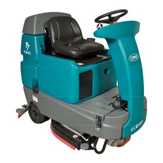
Tennant T7 Operator's Manual
Scrubber dryer
Hide thumbs
Also See for TENNANT T7:
- Service information manual (88 pages) ,
- Operator's manual (54 pages) ,
- Instruction bulletin (11 pages)
Table of Contents
Troubleshooting

Related Manuals for Tennant TENNANT T7


Summary of Contents for Tennant TENNANT T7
- Page 1 TENNANT T7 SCRUBBER DRYER OPERATOR MANUAL Clemas & Co. Unit 5 Ashchurch Business Centre, Alexandra Way, Tewkesbury, Gloucestershire, GL20 8NB. Tel: 01684 850777 Fax: 01684 850707 Email: info@clemas.co.uk Web: www.clemas.co.uk...
-
Page 2: Safety Precautions
SAFETY PRECAUTIONS The safety labels appear on the machine in the locations indicated. If these or any label becomes damaged or illegible, install a new label in its place. BATTERY CHARGING LABEL - - LOCATED FLAMMABLE SPILLS LABEL - - LOCATED ON THE SEAT PANEL ON THE SEAT PANEL FOR SAFETY LABEL - -... -
Page 3: Operation
OPERATION OPERATION MACHINE COMPONENTS A. Recovery tank drain hose K. Tool Box or B. Recovery tank cover optional FaST- -PAK compartment C. Recovery tank L. Solution tank fill cap D. Operator seat M. Solution tank drain hose E. Batteries N. Squeegee hose F. -
Page 4: Controls And Instruments
OPERATION CONTROLS AND INSTRUMENTS A. Solution tank empty indicator B. Recovery tank full indicator C. Battery charge level indicators D. Fault indicator E. Emergency Stop Button F. Directional switch G. Horn button H. On/Off key switch I. One Step scrub button J. -
Page 5: How The Machine Works
OPERATION FOAM SCRUBBING SYSTEM (FAST MODE) HOW THE MACHINE WORKS Unlike conventional scrubbing, the optional FaST (Foam Scrubbing Technology) system operates by The machine solution tank, scrub brushes, injecting the FaST--PAK concentrate agent into squeegee, vacuum fan, and recovery tank work the system with a small amount of water and air. -
Page 6: Brush Information
OPERATION BRUSH INFORMATION MACHINE SETUP ATTACHING SQUEEGEE ASSEMBLY For best results, use the correct brush type for the cleaning application. The following are 1. Stop machine on a level surface. recommended brush applications. 2. Turn the machine ON/OFF key switch off. FOR SAFETY: Before leaving or servicing machine, stop on level surface, and turn off machine. - Page 7 OPERATION FILLING THE SOLUTION TANK MACHINE OPERATION The machine is equipped with a fill port at the rear of the machine. PRE- -OPERATION CHECKLIST - Check the battery fluid and charge level. - Check the tank cover seals for damage and wear.
- Page 8 OPERATION SETTING SCRUB MODES SETTING SOLUTION FLOW LEVEL (CONVENTIONAL SCRUBBING ONLY) Before scrubbing, determine which scrub mode will be used (FaST or conventional). Then set the NOTE: The solution flow cannot be adjusted when scrub brush pressure and if conventional the machine is in the FaST mode.
- Page 9 OPERATION SCRUBBING 3. Place the directional switch in the direction the machine is to be moved (forward or reverse). FOR SAFETY: Do not operate machine, unless operator manual is read and understood. NOTE: The machine can scrub in both forward or reverse.
-
Page 10: Double Scrubbing
OPERATION 6. The Brake pedal can be used to control the DOUBLE SCRUBBING machine if quicker stopping is needed or if For heavily soiled areas, use the double scrubbing operating on an incline. Do not operate method. machine on inclines exceeding 7% (4_) when scrubbing. -
Page 11: Water Pickup Mode (No Scrubbing)
OPERATION Place the side squeegees back on to the machine WATER PICKUP MODE (NO SCRUBBING) before scrubbing the floor the second time. The machine can be used to pick up water or non--flammable liquid spills without scrubbing. NOTE: It is easier to put the side squeegees back on to the machine with the scrub head To pick up water or non--flammable liquid spills, partially lowered. -
Page 12: While Operating The Machine
OPERATION WHILE OPERATING THE MACHINE EMERGENCY STOP BUTTON Drive as straight a path as possible. Avoid The Emergency Stop Button halts all power to the bumping into posts or scraping the sides of the machine in case of an emergency. Press the machine. -
Page 13: Solution Tank Empty Indicator
OPERATION SOLUTION TANK EMPTY INDICATOR BATTERY DISCHARGE INDICATOR The solution tank empty indicator comes on when The battery discharge indicator shows the charge the solution tank is empty. When this happens, the level of the batteries. scrub functions are disabled. If necessary, press the ONE STEP Scrub button for an additional minute of operation to pick up standing water or solution. -
Page 14: Fault Indicator
OPERATION FAULT INDICATOR The fault indicator light (shown in upper right) comes on when there a fault is detected in the propelling motor, vacuum fan motor, or brush motors. Refer to the table below to determine the cause for the fault or failure. Indicator(s) Cause(s) Remedy... -
Page 15: Circuit Breakers
OPERATION CIRCUIT BREAKERS FUSES Circuit breakers are resettable electrical circuit The fuse is a one-time protection device designed protection devices that stop the flow of current in to stop the flow of current in the event of a circuit the event of a circuit overload. Once a circuit overload. -
Page 16: Draining And Cleaning The Tanks
OPERATION DRAINING AND CLEANING THE TANKS When cleaning is finished, or when the recovery tank full indicator comes on, the recovery tank should be drained and cleaned. The solution tank then can be filled again for additional cleaning. 1. Drive the machine to a solution disposal drain. 2. - Page 17 OPERATION 9. Close the recovery tank cover. 13. Carefully push the recovery tank forward to close the solution tank. 10.Remove the solution tank drain hose. While holding the hose up, remove the plug, then slowly lower the drain hose to the floor drain or sink.
-
Page 18: Propel System Troubleshooting
OPERATION 16. Cylinderical scrub head: Remove and clean the debris tray. Place the tray back in the scrub head when finished. 17. Replace the solution tank drain hose cap and mount the drain hose back onto the mounting clip after after the tank is drained. PROPEL SYSTEM TROUBLESHOOTING The audio alarm (horn) will sound and/or warning lights will come on when a propelling system fault... -
Page 19: Machine Troubleshooting
OPERATION MACHINE TROUBLESHOOTING Problem Cause Remedy Trailing water--poor or no Vacuum fan turned off Turn vacuum fan on water pickup Worn squeegee blades Rotate or replace squeegee blades Squeegee out of adjustment Adjust squeegee Vacuum hose clogged Flush vacuum hoses Vacuum fan filter dirty Clean vacuum fan filter Vacuum fan cover seals worn... - Page 20 OPERATION Problem Cause Remedy Poor scrubbing performance One Step Scrub button not on Turn One Step Scrub button on Improper detergent or brushes Contact Tennant service used representative Recovery tank full Empty recovery tank Solution tank empty Fill solution tank Debris caught on scrub brushes or Remove debris pads...
-
Page 21: Maintenance
MAINTENANCE MAINTENANCE T7 331051 (9- -06) Home Find... Go To.. -
Page 22: Maintenance Chart
MAINTENANCE MAINTENANCE CHART No. of Lubricant/ Service Interval Description Procedure Fluid Points Check for damage and wear Daily Side and rear squeegees Check deflection and leveling Scrub brushes / pads Check for damage, wear, debris Recovery tank Clean tank, screen filter, and float sensor Vacuum fan filter Clean... -
Page 23: Lead Acid Batteries
MAINTENANCE BATTERIES LEAD ACID BATTERIES The batteries are designed to hold their power for Check the electrolyte level in each battery cell long periods of time. The lifetime of the batteries before and after charging, and after every 50 is limited to number of charges the batteries hours of operation. -
Page 24: Specific Gravity
MAINTENANCE NOTE: Do not take readings immediately after 4. Lead acid batteries: Check the water level in adding distilled water. If the water and acid are not all battery cells. If the level is low, add just thoroughly mixed, the readings may not be enough distilled water to cover the plates. -
Page 25: Electric Motors
MAINTENANCE 6. Plug the battery charger into the wall outlet. ELECTRIC MOTORS NOTE: If the red “ABNORMAL CYCLE” lamp lights when the TENNANT charger is plugged into The carbon brushes on the vacuum fan motor, the a wall outlet, the charger cannot charge the propelling motor, and the scrub brush motors battery and there is something wrong with the should be inspected after the initial 500 hours of... -
Page 26: Scrub Brushes And Pads
MAINTENANCE REPLACING DISK BRUSHES OR PAD DRIVER SCRUB BRUSHES AND PADS 1. Stop machine on a level surface. Make sure the scrub head is in the raised position. The machine can be equipped with either disk or cylindrical scrub brushes, or cleaning pads. Check 2. -
Page 27: Replacing Disk Pads
MAINTENANCE 5. Pull the scrub brush/pad driver downward to REPLACING DISK PADS remove it from the drive hub. 1. Remove the pad driver from the machine. 2. Squeeze the spring clip together to remove the center disk. 6. Place the new scrub brush/pad driver onto the drive hub. -
Page 28: Replacing Or Rotating Cylinderical Brushes
MAINTENANCE CYLINDERICAL BRUSHES 4. Remove idler plate from the scrub head by pressing the spring tab downward. Check the brush taper and rotate the brushes from front-to-rear every 50 hours of machine operation for maximum brush life and best scrubbing performance. The cylindrical brushes should be replaced if large amounts of bristles are missing, or if the remaining bristle length is less than 15 mm... -
Page 29: Checking Cylinderical Brush Pattern
MAINTENANCE CHECKING CYLINDERICAL BRUSH PATTERN 8. If the width of the brushes is not the same, see ADJUSTING CYLINDERICAL BRUSH 1. Apply chalk, or a similar marking material, to a WIDTH section of this manual. smooth and level section of the floor. NOTE: If chalk or other material is not available, allow the brush to spin on the floor for two minutes. - Page 30 MAINTENANCE 4. Remove idler plate from the scrub head by ADJUSTING CYLINDERICAL BRUSH WIDTH pressing the spring tab downward. 1. Stop machine on a level surface. Make sure the scrub head is in the lowered position. 2. Turn the machine ON/OFF key switch off. FOR SAFETY: Before leaving or servicing machine, stop on level surface, and turn off machine.
-
Page 31: Fast Supply Hose Connector
MAINTENANCE 5. Remove the perforated knock outs from the REPLACING THE FaST- -PAK (FaST Model) new FaST--PAK carton. Do Not remove the bag from the carton. Pull out the hose connector located on the bottom of the bag 1. Stop machine on a level surface. and remove the hose cap from the connector. -
Page 32: Replacing (Or Rotating) The Rear Squeegee Blades
MAINTENANCE 4. Pull the rear squeegee assembly from the SQUEEGEE BLADES machine. 5. Loosen the rear squeegee retaining band The side squeegees control water spray and tension latch and remove the retaining band. channel water into the path of the rear squeegee. The side squeegee blades are not adjustable. - Page 33 MAINTENANCE 8. Install the new front squeegee blade or rotate 12. Tighten the rear squeegee retaining band the existing blade to the new edge. Be sure tension latch. the holes in the front squeegee blade are hooked onto the tabs on the front blade clamp.
-
Page 34: Replacing Side Squeegee Blades
MAINTENANCE REPLACING SIDE SQUEEGEE BLADES LEVELING THE REAR SQUEEGEE 1. Open the side squeegee. Leveling of the squeegee assures the entire length of the squeegee is in even contact with the 2. Pull the old side squeegee blade from the side surface being scrubbed. -
Page 35: Adjusting Rear Squeegee Blade Deflection
MAINTENANCE ADJUSTING REAR SQUEEGEE BLADE 4. If the overall squeegee blade deflection needs DEFLECTION to be adjusted, loosen the jam nuts on the squeegee casters and adjust the height. Deflection is the amount of curl the overall squeegee blade has when the machine moves forward. - Page 36 MAINTENANCE SOLUTION TANK SEALS SKIRTS AND SEALS There are two solution tank seals. Check the seal for damage and wear after every 100 hours of operation. DISK SCRUB HEAD FLOOR SKIRT The skirt is located in front of the disc brush scrub A front seal is located on the bottom of the heads.
-
Page 37: Pushing, Towing, And Transporting The Machine
MAINTENANCE FOR SAFETY: Do not operate machine with PUSHING, TOWING, AND TRANSPORTING the brake disabled. THE MACHINE TRANSPORTING THE MACHINE When transporting the machine by trailer or truck, PUSHING OR TOWING THE MACHINE be certain to follow the tie--down procedure below: If the machine becomes disabled, it can be 1. -
Page 38: Machine Jacking
MAINTENANCE MACHINE JACKING STORAGE INFORMATION Empty the recovery and solution tanks before The following steps should be taken when storing jacking the machine. Jack up the machine for the machine for extended periods of time. service at the designated locations. Use a hoist or 1.
Need help?
Do you have a question about the TENNANT T7 and is the answer not in the manual?
Questions and answers