Table of Contents
Advertisement
Quick Links
®
Hygenic
Fully Cleanable Recovery Tank
®
TennantTrue
Parts
ATTENTION: DO NOT tip the machine onto its side to replace parts or perform any
maintenance procedures. Sensitive robotic components could be damaged or bumped
out of adjustment if the machine is tipped onto its side.
ATTENTION: DO NOT remove and/or adjust the upper or lower LIDARs, any of the
3D cameras, or remove/move shrouds or brackets on which these components are
mounted. Due to calibration the LIDARS and 3D cameras cannot be adjusted in the fi eld.
For the latest Parts Manuals and other
language Operator Manuals, visit:
www.tennantco.com/manuals
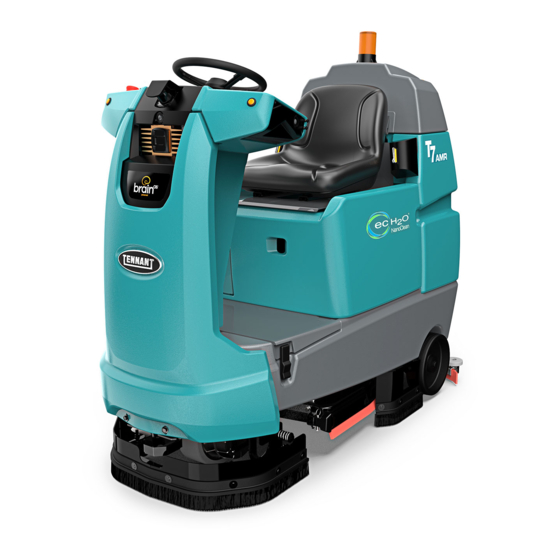
T7AMR
Rider-Scrubber
English EN
Service Manual
9018143
Rev. 00 (01-2019)
*9016605*
R
Advertisement
Table of Contents
Troubleshooting

Related Manuals for Tennant T7AMR


Summary of Contents for Tennant T7AMR
- Page 1 T7AMR Rider-Scrubber English EN Service Manual ® Hygenic Fully Cleanable Recovery Tank ® TennantTrue Parts ATTENTION: DO NOT tip the machine onto its side to replace parts or perform any maintenance procedures. Sensitive robotic components could be damaged or bumped out of adjustment if the machine is tipped onto its side.
- Page 2 This product may contain portions of software that have various 3rd party licenses. More information can be found at: www.tennantco. com/opensource Specifi cations and parts are subject to change without notice. Original Instructions. Copyright © 2019 Tennant Company. All rights reserved.
-
Page 3: Table Of Contents
Input Check/Output Check ec-H2O Water Conditioning (Diagnostic Test) ........56 Cartridge Replacement .......34 Dashboard Check ........58 Lubrication ............35 Fault Codes ...........59 Steering Gear Chain ........35 ec-H2O NanoClean Icon Faults ....62 Steering U-Joint ........35 Off-Board Charger Error And Fault Codes .........64 T7AMR 9018143 (01-2019) - Page 4 Remove/Reinstall/Replace The Battery Box Cover .......88 Contactor ...........115 Front Covers Group .........90 Remove/Reinstall/Replace The Main Frame Group ........91 Kinetek Controller ......118 Controls/Sensors/Cameras ......92 Battery Group ..........120 Instrument Panel Group ........92 Remove/Reinstall/Replace The Touchscreen ........93 Remove/Reinstall/Replace The Control Panel........93 T7AMR 9018143 (01-2019)
- Page 5 Remove/Reinstall/Replace The ec-H2O Solution Pump (Option)..147 Remove/Reinstall/Replace The ec-H2O Pressure Switch (Option) ..147 Remove/Reinstall/Replace The ec-H2O Module (Option) ....148 Service The ec-H2O Module (Option) ..150 Connect Hoses To PTC (Push-To-Connect) Fittings....152 Disconnect Hoses From PTC (Push-To-Connect) Fittings....153 T7AMR 9018143 (01-2019)
-
Page 6: Safety Precautions
- In areas with possible falling objects. personal injury or death. - With pads or accessories not supplied or approved by Tennant. The use of other pads FOR SAFETY: To identify actions that must be may impair safety. followed for safe operation of equipment. - Page 7 - Do not modify the machine from its original 5. Before leaving or servicing machine: design. - Stop on level surface. - Use Tennant supplied or approved replacement - Turn off machine and remove key. parts. T7AMR 9018143 (01-2019)
- Page 8 380 mm (15 in) or less from the ground. - Do not load/unload on ramp inclines that exceed 15.8% grade. - Turn off machine and remove key. - Use tie-down straps to secure machine. T7AMR 9018143 (01-2019)
- Page 9 Do not use N’utilisez pas de o incendios. panel. flammable matières No utilice materials in inflammables materiales tank. dans le(s) inflamables en réservoir(s). el depósito(s). 25815 Located under the solution fi ll port and next to foot pedals. T7AMR 9018143 (01-2019)
-
Page 10: General Information
H. Recovery tank cover V. Solution tank fi ll cap I. Flashing light W. Rear squeegee J. Operator seat K. Batteries X. Squeegee vacuum hose Y. Steering wheel L. Battery charging connector M. Solution tank front cover T7AMR 9018143 (01-2019) -
Page 11: Controls And Instruments
L. Directional switch C. 1-Step button M. Blue start/pause button D. Horn button N. Signal lights (Rear) E. Brush pressure button F. Brush pressure indicator lights G. Solution fl ow indicator lights H. Solution fl ow button T7AMR 9018143 (01-2019) -
Page 12: Cameras And Sensors
C. Sensors – Front 2D camera D. Sensors – Front 3D camera E. Sensors - Side 2D camera (located on each side of machine) F. Sensors - Side 3D camera (located on each side of machine) G. Sensors - Lower LIDAR T7AMR 9018143 (01-2019) - Page 13 GENERAL INFORMATION T7AMR 9018143 (01-2019)
-
Page 14: Electrical Schematic Symbols
3 Phase AC Induction Motor Energized Relay Coil Adaptor Harness Motor Encoder N.C. Relay Contacts Sensor (Variable Resistor) Notes N.O. Relay Contacts Momenary Switch N.O. Assembly Horn or Alarm Contact Switch N.C. AC Plug Solenoid Valve Capacitor Light T7AMR 9018143 (01-2019) -
Page 15: Electrical Schematic
GENERAL INFORMATION ELECTRICAL SCHEMATIC - PAGE 1 T7AMR 9018143 (01-2019) -
Page 16: Electrical Schematic
GENERAL INFORMATION ELECTRICAL SCHEMATIC - PAGE 2 T7AMR 9018143 (01-2019) -
Page 17: Electrical Schematic
GENERAL INFORMATION ELECTRICAL SCHEMATIC - PAGE 3 T7AMR 9018143 (01-2019) -
Page 18: Electrical Schematic
GENERAL INFORMATION ELECTRICAL SCHEMATIC - PAGE 4 T7AMR 9018143 (01-2019) -
Page 19: Electrical Schematic
GENERAL INFORMATION ELECTRICAL SCHEMATIC - PAGE 5 T7AMR 9018143 (01-2019) -
Page 20: Fastener Torque
424 - 550 Nm 508 - 660 Nm 177 - 230 Nm 409 - 530 Nm 574 - 745 Nm 686 - 890 Nm 227 - 295 Nm 520 - 675 Nm 732 - 950 Nm 879 - 1140 Nm T7AMR 9018143 (01-2019) -
Page 21: General Machine Dimensions/Capacities/Performance
Maximum rated climb and descent angle with empty tanks (Manual Mode) 15.8% Maximum rated climb and descent angle when scrubbing (Manual Mode) ° 0 ° 4 Minimum temperature for operating machine scrubbing functions 2° C (36° F) T7AMR 9018143 (01-2019) - Page 22 80 mm wide x 260 mm OD (3.0 in wide x 10 in OD) ec H2O SYSTEM Item Measure Solution pump 24 Volt DC, 5A, 5.7 LPM (1.5 GPM) open ow, 70 psi bypass setting Solution ow rate Low: 0.14 gpm Medium: 0.25 gpm High: 0.35 gpm T7AMR 9018143 (01-2019)
-
Page 23: Machine Dimensions
GENERAL INFORMATION MACHINE DIMENSIONS 740 mm (29 in) 800 mm 850 mm (31.5 in) (34 in) 1450 mm (57 in) Track Wheel base (at rear wheels) 971 mm 724 mm (31.2 in) (28.5 in) 1645 mm (65 in) T7AMR 9018143 (01-2019) -
Page 24: Maintenance
MAINTENANCE MAINTENANCE T7AMR 9018143 (01-2019) -
Page 25: Maintenance Chart
(Check every 100 hours after initial 500 hour check) Propelling motor Check motor brushes (Check every 100 hours after initial 500 hour check) Tires Check for damage and wear LUBRICANT/FLUID Distilled water SAE 90 weight gear lubricant T7AMR 9018143 (01-2019) -
Page 26: Batteries
Do not remove battery caps when NOTE: Do Not check the electrolyte level if the cleaning batteries. machine is equipped with a battery watering system. 08247 FOR SAFETY: When servicing machine, keep all metal objects off batteries. Avoid contact with battery acid. T7AMR 9018143 (01-2019) -
Page 27: Charging The Batteries
Refer to the off-board battery charger owners use of other battery chargers that are not supplied manual for operating instructions. and approved by Tennant are prohibited. Refer to the charger owners manual for additional information. FOR SAFETY: Do not disconnect the off-board Contact distributor or Tennant for battery charger charger’s DC cord from the machine’s receptacle... -
Page 28: Hydrolink Battery Watering System (Trojan Battery Option)
6. After adding water, replace the dust cap on the battery fi ll hose and store the hand pump hose inside the machine’s battery compartment for future use. T7AMR 9018143 (01-2019) -
Page 29: Circuit Breakers And Fuses
500 hours of machine operation and then every 100 hours after the initial Circuit Rating Circuit Protected 500 hours. Breaker Instrument panel - power Accessories 20 A AMR system 10 A Brain module T7AMR 9018143 (01-2019) -
Page 30: Cameras And Sensors
Side 2D and 3D cameras are located on each side of are completely clear of all dirt, smudges, and/or the machine. other debris. Use a fl ash light to inspect these sensor surfaces and ensure they are thoroughly cleaned. T7AMR 9018143 (01-2019) -
Page 31: Scrub Brushes And Pads
1. Stop machine on a level surface. Make sure the scrub head is in the raised position. 2. Turn the machine ON/OFF key switch off. FOR SAFETY: Before leaving or servicing machine, stop on level surface, turn off machine, and remove key. T7AMR 9018143 (01-2019) - Page 32 10. If the scrub brush located on the left side of the 7. Set the yellow spring clip to the open position to machine was changed/removed: Close and make brush installation easier. Press spring clip resecure the left perimeter guard. together and downward to set. T7AMR 9018143 (01-2019)
-
Page 33: Replacing Disk Pads
3. Flip or replace the scrub pad, center the scrub pad on the pad driver. Then reinstall the center disk to secure the pad in place on the pad driver. 4. Reinsert the pad driver into the machine. T7AMR 9018143 (01-2019) -
Page 34: Ec-H2O System
5. Install the new cartridge and reconnect the two hoses. Make sure the hose connectors are fully inserted into new cartridge. 2. Remove the battery compartment shroud from machine to access cartridge. T7AMR 9018143 (01-2019) -
Page 35: Lubrication
STEERING U-JOINT The steering u-joint is located directly below the steering motor. Check for damage or wear and Solution flow button lubricate the steering u-joint after every 200 hours. 7. Reinstall the battery compartment shroud and operator seat. T7AMR 9018143 (01-2019) -
Page 36: Squeegee Blades
Then loosen both rear squeegee assembly mounting knobs. 7. Loosen the two outer knobs on the rear squeegee assembly. Remove the front squeegee blade from the squeegee assembly. 4. Pull the rear squeegee assembly from the machine. T7AMR 9018143 (01-2019) - Page 37 14. Reinstall the squeegee vacuum hose onto the rear squeegee assembly. 11. Reinstall the rear squeegee retaining band onto the squeegee assembly. Be sure each of the fl anges on the retaining band are seated in the cut outs in the rear squeegee assembly. T7AMR 9018143 (01-2019)
-
Page 38: Replacing The Side Squeegee Blades
The squeegee blade end should be further away from the wall when the fl oor curves up into the wall. 2. Open the side squeegee. T7AMR 9018143 (01-2019) -
Page 39: Leveling The Rear Squeegee
5. Drive the machine forward again to recheck the 6. Readjust the squeegee blade defl ection if squeegee blade defl ection after adjustments are necessary. made. 6. Readjust the squeegee blade defl ection if necessary. T7AMR 9018143 (01-2019) -
Page 40: Skirts And Seals
The skirts should clear the fl oor by 0 to 6 mm (0 to 0.25 in) when the scrub brushes are new and the scrub head is down. The bristles should lightly touch the fl oor. Replace damaged and/or worn bristle assemblies. T7AMR 9018143 (01-2019) -
Page 41: Recovery Tank Seal
There are two solution tank seals. Check the seal for damage and wear after every 100 hours of operation. A front seal is located on the bottom of the solution tank cover. A rear seal is located on the bottom of the recovery tank. T7AMR 9018143 (01-2019) -
Page 42: Pushing, Towing, And Transporting The Machine
Immediately after pushing the machine, remove the screw driver from between the brake release lever and the body of the encoder. NEVER operate the machine with the parking brake disabled. FOR SAFETY: Do not operate machine with the brake disabled. T7AMR 9018143 (01-2019) -
Page 43: Jacking Up The Machine
10. Route the rear tie-down straps through the opening at the center part of the rear axle. 11. Stow/secure all parts removed from the machine in a safe place where they will not be lost or damaged. T7AMR 9018143 (01-2019) -
Page 44: Storage Information
FOR SAFETY: When servicing machine, block machine tires before jacking machine up. Use a hoist or jack that will support the weight of the machine. Jack machine up at designated locations only. Block machine up with jack stands. T7AMR 9018143 (01-2019) - Page 45 MAINTENANCE T7AMR 9018143 (01-2019)
-
Page 46: Troubleshooting
Always check these items before conducting more labor intensive troubleshooting requiring the machine to be disassembled and the T7AMR SERVICE CONNECTION diagnostics software application to be used. Function... - Page 47 • Recovery tank not full • Recovery tank full • E-Stops not engaged • E-Stops engaged • Charger interlock not engaged • Charger interlock engaged • No faults on ec-H2O enable output • Faults on ec-H2O enable output T7AMR 9018143 (01-2019)
-
Page 48: Service Diagnostics Tool
Kinetek Control Module. Authorized service providers can download the Service Diagnostics software. Tennant Service personnel have this software installed on their service devices. Use the AMR Service Connector to connect the service device to the Kinetek Control Module. The Kinetek Control Module stores confi... -
Page 49: Prepare The Machine For Troubleshooting/Diagnostics/File Transfers
3. Disconnect the main wire harness SCRUB CONTROLLER connector from the Kinetek Control Module P4: CAN/Programming terminal. 4. Connect the AMR SERVICE CONNECTOR to the service device. 3. Contact the Tennant Customer Service Department for additional troubleshooting/diagnostic guidance. T7AMR 9018143 (01-2019) - Page 50 16. Press the DIAGNOSTIC ON button to activate the Output Check (Diagnostic Test) function of the T7AMR Diagnostic Test application. See INPUT CHECK/OUTPUT CHECK (DIAGNOSTIC TEST). 7. Remove the front perimeter guard from the machine.
- Page 51 24. Reinstall the controller cover plate onto the machine. 25. Reinstall the battery box cover and operator seat/ seat plate onto the machine. See REMOVE/ INSTALL THE OPERATOR SEAT/BATTERY BOX COVER. 26. Reconnect the main wire harness to the operator seat switch cable. T7AMR 9018143 (01-2019)
-
Page 52: Diagnostic Tools
Erasable Programmable Read-Only Memory) Checksum are listed. Confi rm these three numbers to ensure the latest version of the fi rmware is installed on the machine. Contact the Tennant Customer Service Department for the latest controller fi rmware version, Firmware Rev, and EEPROM. -
Page 53: Output Information/Current And Volts
In the above example the error code of 0X31 shows there is a brush adjustment timeout error. NOTE: The letters FWD in the TRACT DIRECT cell indicate the machine is in the forward direction for the testing being conducted. T7AMR 9018143 (01-2019) - Page 54 Tract Running cell is active and there are no faults. If the numeral 1 was in either the Tract Open or Tract Short cell, this would indicated there was either an Open or Short fault condition with that system and additional troubleshooting is required. T7AMR 9018143 (01-2019)
-
Page 55: Machine System Ranges
TROUBLESHOOTING MACHINE SYSTEM RANGES Refer to the below table to confi rm voltage/amp when using the T7AMR SERVICE CONNECTION diagnostics software application for machine troubleshooting. System Component Minimum Nominal Maximum Measure Value Value Value Propel Traction Current -120 Amps Traction Voltage (Forward) -
Page 56: Input Check/Output Check (Diagnostic Test)
The indicator is red when the solution tank is empty. Service Pedal: The Service Pedal indicator is green when the service brake is not depressed. The indicator is red when the brake pedal is pressed. T7AMR 9018143 (01-2019) - Page 57 Check the Output Information column to confi rm the tests are completed. If all cells in the Output Information column are 0 (zero), then no tests are active. T7AMR 9018143 (01-2019)
-
Page 58: Dashboard Check
fl ow is set to the lowest level, yellow when the solution fl ow is set to the medium level, and red when the solution fl ow is at the high level. T7AMR 9018143 (01-2019) -
Page 59: Fault Codes
1. Charge batteries. (All Functions Off) 2. Parameter”Battery Voltage” set to 1 but 2. Power cycle machine. actual battery is 24V. 3. Contact Tennant Customer Service 3. Controller hardware fault. Department. 0x21 Battery Low 1. Battery voltage is less than set parameter 1. - Page 60 1. Brush motor short circuit. 1. Power cycle machine. Protection 2. Troubleshoot scrub motor circuit. 0x59 Traction Left Drain Fault 1. Controller hardware fault. 1. Contact Tennant Customer Service Department. 0x5B Traction Right Drain 1. Controller hardware fault. 1. Contact Tennant Customer Service Fault Department.
- Page 61 0x76 Precharge Failure 1. Wiring problem. 1. Power cycle machine. (Others) 2. Controller hardware fault. 2. Contact Tennant Customer Service Department. 0x77 Brush Motor Stalled 1. Brush motor stalled. 1. Power cycle machine. 2. Parameter ”Brush Current Limit” set too low.
-
Page 62: Ec-H2O Nanoclean Icon Faults
Refer to ec-H2O NanoClean blink Electrode Fault allowed operating condition. Troubleshooting Guide. Fast 0x0726 ec-H2O Cell 1. Shorted load condition Refer to ec-H2O NanoClean blink Short Warning 2. Higher current draw than Troubleshooting Guide hardware design limit. T7AMR 9018143 (01-2019) - Page 63 fl ashing blue light on ec-H2O module. Red- 0x0707 ec-H2O Water 1. ec-H2O water cartridge has 1. Replace ec-H2O water conditioning Green/ Conditioning expired due to either gallons of cartridge. Red-Blue Cartridge Expired usage or 2 years of use. Warning T7AMR 9018143 (01-2019)
-
Page 64: Off-Board Charger Error And Fault Codes
30 seconds and retry charger. If it fails F-0-0-3 again, contact vehicle or machine F-0-0-4 manufacturer. F-0-0-6 Off-Board Charger Error and Fault Codes table taken from the Delta-Q IC650 Charger Manual. © Delta-Q Technologies Corp. (PN: 710-0138 Rev 3 Date: 14/07/2014) T7AMR 9018143 (01-2019) - Page 65 TROUBLESHOOTING T7AMR 9018143 (01-2019)
-
Page 66: Off-Board Battery Charging On
13L/BLK 63/ORA 64/YEL 64C/YEL J6-5 J6-3 Vehicle Interface Board By-Pass Switch 68/GRY 68A/GRY 79/WHT 77/PUR 13B/BLK 13P/BLK SHIELD BRAIN Control Module 68C/GRY PWR-CONN 68B/GRY 68D/GRY 13R/BLK Battery Positive + PWR-CONN 13Q/BLK 13S/BLK Battery Negative - Steering Motor T7AMR 9018143 (01-2019) -
Page 67: Batteries Fail To Charge/Reduced Run Time (Off-Board Charger)
• Are all battery cells within 0.050 (50 points) specifi c gravity of each other? Terms: AC = Alternating Current AGM = Absorbed Glass Mat Specifi c Gravity = Relative density of a substance compared to water (1.000 specifi c gravity) T7AMR 9018143 (01-2019) -
Page 68: Power Up On
E-Stop OUT 67C/PUR BRAIN Control Module 13N/BLK 13U/BLK 68C/GRY 68B/GRY PWR-CONN 13Q/BLK 68D/GRY 68C/GRY PWR-CONN 68D/GRY Steering Motor Fuse 13X/BLK 54/BRN 54/YEL 54A/YEL 54B/YEL 13W/BLK Battery Positive + 64/YEL 13Y/BLK Battery Negative - Pressure EC-H20 Module Switch T7AMR 9018143 (01-2019) -
Page 69: Machine Failed To Power Up
• Move the AMR Bypass Switch to “O” (OFF) position Brain Control replace necessary • Test voltage applied to power-up subsystem as Module lower components shown on electrical schematic harness • Are electrical circuit operating as shown on electrical schematic? Terms: VDC = DC Voltage T7AMR 9018143 (01-2019) -
Page 70: Propel System
93/ORA Forward Forward J10-1 94/YEL Common Common J10-2 95/GRN Backward Backward J10-3 96/BLU Fwd-LED Rev-LED J10-4 97/PUR Bwd-LED Fwd-LED J10-5 98/GRY Fwd-5V Battery Positive + J10-6 Directional Vehicle Interface Battery Negative - 99/WHT Rev-5V Switch Board J10-7 T7AMR 9018143 (01-2019) -
Page 71: Propel System Operational Matrix
• Use a voltmeter to test the total battery voltage power-up circuit • Is total battery voltage greater than 18 VDC? operation • Key OFF Use T7AMR Service Identify voltage drop Connection to read location and repair or • Place machine on blocks so drive wheel is lifted from... -
Page 72: Scrub Motor On
Actuator A Squeegee Squeegee Actuator Actuator (Disk) (Cylinder) 18/GRY 18A/GRY Squeegee Actuator B P2-11 18B/GRY 60/TAN Water Solenoid [+] P2-8 60A/TAN Water Solenoid Vehicle Controller 16A/BLU 16/BLU Water Solenoid [-] Battery Positive + P2-9 Battery Negative - T7AMR 9018143 (01-2019) -
Page 73: Scrub Motor Operational Matrix
• Faults on scrub motor output SCRUB MOTOR FAILED TO TURN ON Step Action Value(s) Yes • Key ON Use T7AMR Service Proceed to STEP 2 Connection to read • Enable scrub motor error code from • Is there a fault on the membrane panel? controller •... -
Page 74: Scrub Head Lift
Actuator A Squeegee Squeegee Actuator Actuator (Disk) (Cylinder) 18/GRY 18A/GRY Squeegee Actuator B P2-11 18B/GRY 60/TAN Water Solenoid [+] P2-8 60A/TAN Water Solenoid Vehicle Controller 16A/BLU 16/BLU Water Solenoid [-] Battery Positive + P2-9 Battery Negative - T7AMR 9018143 (01-2019) -
Page 75: Scrub Head Actuator Operational Matrix
• No faults on scrub deck actuator output SCRUB HEAD FAILED TO LIFT/LOWER Step Action Value(s) • Key ON Use T7AMR Service Proceed to STEP 2 Connection to read • Enable lift actuator error code from • Is there a fault on the membrane panel? controller •... -
Page 76: Rear Squeegee Lift
Actuator A Squeegee Squeegee Actuator Actuator (Disk) (Cylinder) 18/GRY 18A/GRY Squeegee Actuator B P2-11 18B/GRY 60/TAN Water Solenoid [+] P2-8 60A/TAN Water Solenoid Vehicle Controller 16A/BLU 16/BLU Water Solenoid [-] Battery Positive + P2-9 Battery Negative - T7AMR 9018143 (01-2019) -
Page 77: Rear Squeegee Actuator Operational Matrix
• No faults on squeegee actuator output REAR SQUEEGEE FAILED TO LIFT/LOWER Step Action Value(s) Yes • Key ON Use T7AMR Service Proceed to STEP 2 Connection to read • Enable lift actuator error code from • Is there a fault on the membrane panel? controller •... -
Page 78: Vacuum Fan On
Actuator A Squeegee Squeegee Actuator Actuator (Disk) (Cylinder) 18/GRY 18A/GRY Squeegee Actuator B P2-11 18B/GRY 60/TAN Water Solenoid [+] P2-8 60A/TAN Water Solenoid Vehicle Controller 16A/BLU 16/BLU Water Solenoid [-] Battery Positive + P2-9 Battery Negative - T7AMR 9018143 (01-2019) -
Page 79: Vacuum Fan Operational Matrix
• No faults on vacuum fan output VACUUM FAN FAILED TO TURN ON Step Action Value(s) Yes • Key ON Use T7AMR Service Proceed to STEP 2 Connection to read • Enable vacuum fan error code from • Is there a fault on the membrane panel? controller •... -
Page 80: Solution Control On (Conventional)
Actuator A Squeegee Squeegee Actuator Actuator (Disk) (Cylinder) 18/GRY 18A/GRY Squeegee Actuator B P2-11 18B/GRY 60/TAN Water Solenoid [+] P2-8 60A/TAN Water Solenoid Vehicle Controller 16A/BLU 16/BLU Water Solenoid [-] Battery Positive + P2-9 Battery Negative - T7AMR 9018143 (01-2019) -
Page 81: Solution Control Operational Matrix
2.0 S On / 0.0 S Off SOLUTION CONTROL FAILED TO TURN ON Step Action Value(s) • Key ON Use T7AMR Service Proceed to STEP 2 Connection to read • Enable solution control (conventional) error code from • Is there a fault on the membrane panel? controller •... -
Page 82: Solution Control On (Ec-H2O) (Option)
SOLUTION CONTROL ON (ec-H2O) (OPTION) 13/BLK 13A/BLK 3/ORA BAT - Fuse BAT + 100A 22/BRN EC_ENABLE P3-6 Vehicle Controller Fuse 13X/BLK 52/BRN 54/YEL 54A/YEL 54B/YEL 13W/BLK Battery Positive + 64/YEL 13Y/BLK Battery Negative - 22/BRN ENABLE SIGNAL Pressure EC-H20 Module Switch T7AMR 9018143 (01-2019) -
Page 83: Solution Control (Ec-H2O) Operational Matrix (Optional)
SOLUTION CONTROL FAILED TO TURN ON (ec-H2O) (OPTIONAL) Step Action Value(s) Yes • Key ON Use T7AMR Service Proceed to STEP 2 Connection to read • Enable solution control (ec-H2O) error code from • Is there a fault on the membrane panel? controller •... -
Page 84: Can Open Network Issues
2. Locate a CAN node location on the machine. 3. Carefully push probes into the back of the connector containing the CAN wires. 4. Since the network remains connected in this node, resistance should measure approximately 61 Ohms. T7AMR 9018143 (01-2019) - Page 85 TROUBLESHOOTING T7AMR 9018143 (01-2019)
-
Page 86: Service
Solution tank bracket Left guard pivot plate Rubber Sensor guard wheel Solution tank bracket Flange Flange sleeve bushing Spring Flange bushing Guard Flange block sleeve Swivel caster Front guard Spring Swivel caster FRONT Front guard bristles T7AMR 9018143 (01-2019) - Page 87 4. Remove all hardware (hex screws, springs, fl at washers, and pins) securing the support bracket to the mounting bracket installed on the stabilizer located on the front right side of the machine. 5. Pull the support bracket assembly from under the machine. T7AMR 9018143 (01-2019)
-
Page 88: Remove/Reinstall Operator Seat
REMOVE/REINSTALL OPERATOR SEAT/BATTERY BOX COVER Seat FRONT Seat switch Spacer (Qty. 4) Seat slide adjustment rail Seat slide Seat harness adjustment rail w/latch Molding Spring Seat plate Sleeve Battery box cover Closed rubber seal Seat stop plate Cover T7AMR 9018143 (01-2019) - Page 89 4. Disconnect the main wire harness from the operator seat switch harness. 7. Remove the battery box cover from the machine. 5. Tilt the recovery tank back. Ensure the recovery tank is empty before tilting. 8. Reinstall removed items in reverse order of disassembly. T7AMR 9018143 (01-2019)
-
Page 90: Front Covers Group
3D cameras (3D cameras cannot be adjusted in the field), Do Not remove instrument shroud from machine. Front shroud Instrument shroud* Camera Center bracket bezel Controller access cover Steering column Bezel mounting bracket Lower sensor Column bracket access panel FRONT T7AMR 9018143 (01-2019) -
Page 91: Main Frame Group
(Qty. 5) Retaining ring Right rear guard bracket Right rear guard bristles Solid tire Vinyl assembly Horn Left rear guard Static strap bracket Main w/grommet frame FRONT Left rear Hitch pin guard Left rear guard bristles T7AMR 9018143 (01-2019) -
Page 92: Controls/Sensors/Cameras
Brain Control Telemetry Light Module controller marker Camera mounting plate Shroud 2D Camera Light marker Right bezel Left side Right side Camera 3D camera* 3D camera* mounting plate Antenna mounting FRONT angle Left bezel Antenna Antenna bracket T7AMR 9018143 (01-2019) -
Page 93: Remove/Reinstall/Replace The Touchscreen
9. Reinstall the control panel onto the steering when lifting the touchscreen from the steering shroud. shroud. 10. Contact Tennant Customer Service Department for 7. If replacing the touchscreen or if the touchscreen instructions for returning components for inspection must be completely removed to service or replace and tracking. -
Page 94: Remove/Reinstall/Replace The On/Off Key Switch, Directional Switch, Ec-H2O Light, And E-Stop (Emergency Stop) Button
7. Connect the main wire harness to the marker light(s). Lock ring Control panel 8. Reinstall the control panel and/or touchscreen onto Emergency Lock ring shutoff switch the shroud. Direction switch electric harness switch T7AMR 9018143 (01-2019) -
Page 95: Remove/Reinstall/Replace The Antenna
12. Reinstall components removed to access the antenna in reverse order of disassembly. 13. Contact Tennant Customer Service Department for instructions for returning components for inspection and tracking. NOTE: Do Not discard AMR components replaced in this procedure. All AMR components must be returned for inspection and tracking purposes. -
Page 96: Remove/Reinstall/Replace The Telemetry Controller
10. Reinstall components removed to access the telemetry controller in reverse order of disassembly. 11. Contact Tennant Customer Service Department for instructions for returning components for inspection and tracking. NOTE: Do Not discard AMR components replaced in this procedure. All AMR components must be returned for inspection and tracking purposes. -
Page 97: Remove/Reinstall/Replace The Membrane Controller
10. Install the circuit board cover/membrane controller cover onto the control panel. 11. Connect the wire harness to the membrane controller. 12. Reinstall components removed to access the membrane controller in reverse order of disassembly. Telemetry controller T7AMR 9018143 (01-2019) -
Page 98: Remove/Reinstall/Replace The Side 2D Cameras
NOTE: To avoid damaging electronic components, 11. Contact Tennant Customer Service Department for a static ground strap must be worn at all times while instructions for returning components for inspection handling electrical components. -
Page 99: Maintaining The Side 3D Cameras
MAINTAINING THE SIDE 3D CAMERAS NOTE: Due to calibration/adjustments required after replacement, neither side 3D camera can be replaced/ adjusted in the fi eld. Contact Tennant Customer Service Department if either side 3D camera needs to be replaced/adjusted. Clean the side 3D cameras after completing all maintenance/service. -
Page 100: Front Cameras And Sensors
*NOTE: Due to calibration/adjustments required after replacement, neither upper LIDAR, lower LIDAR, nor front 3D camera can be replaced and/or adjusted in the field. Brain Corp. Controller Lower sensor bracket Spring Lower LIDAR plate Range sensor (Lower LIDAR sensor)* T7AMR 9018143 (01-2019) -
Page 101: Maintaining The Upper Lidar And Lower Lidar
3D camera cannot be replaced/ replacement, neither the front LIDAR nor the lower adjusted in the fi eld. Contact the Tennant Customer LIDAR can be replaced and/or adjusted in the fi eld. Service Department if the front 3D camera needs to be Contact the Tennant Customer Service Department if replaced/adjusted. -
Page 102: Remove/Reinstall/Replace The Front 2D Camera
8. Connect the wire harness to the front 2D camera. 9. Reinstall components removed to access the front 2D camera in reverse order of disassembly. 10. Contact Tennant Customer Service Department for instructions for returning components for inspection and tracking. -
Page 103: Remove/Reinstall/Replace The Brain Controller
8. Connect the wire harness connections to the Brain controller. 9. Reinstall components removed to access the Brain controller in reverse order of disassembly. 10. Contact Tennant Customer Service Department for instructions for returning components for inspection and tracking. NOTE: Do Not discard AMR components replaced in this procedure. -
Page 104: Recovery Tank Cover Controls/Components
SERVICE RECOVERY TANK COVER CONTROLS/ COMPONENTS Label Marker light safety Label switch (Start/Pause) lock ring Start/Pause Strobe button assembly light Start/Pause Marker light Foam seal Leaf hinges Recovery tank cover Cover hinges Recovery tank FRONT T7AMR 9018143 (01-2019) -
Page 105: Remove/Reinstall/Replace The Start/Pause Button
4. Carefully pull the blue start/pause button assembly from the recovery tank cover. Do Not break or damage wire/cable connections when pulling the blue start/pause button assembly from the recovery tank cover. T7AMR 9018143 (01-2019) - Page 106 11. Connect the harness connections to the start/ pause button assembly. 12. Install the start/pause button assembly onto the recovery tank cover. 13. Install the start/pause button assembly onto the recovery tank cover. T7AMR 9018143 (01-2019)
-
Page 107: Remove/Reinstall/Replace The Rear E-Stop (Emergency Stop) Button
4. Carefully pull the E-Stop button assembly from the recovery tank cover. Do Not break or damage wire/ cable connections when pulling the E-Stop button assembly from the recovery tank cover. 7. Remove the E-Stop button from the E-Stop mounting plate. T7AMR 9018143 (01-2019) -
Page 108: Remove/Reinstall/Replace The Rear Marker Lights
NOTE: Do not completely remove the recovery tank cover from the machine. All components mounted to the recovery tank cover can be easily accessed with the recovery tank cover installed on the machine. T7AMR 9018143 (01-2019) -
Page 109: Pedals Group
SERVICE PEDALS GROUP Foot pedal Extension spring Foot pedal FRONT (0.35od 0.05wir 02.8l) Extension spring (0.50od 0.07wir 03.0l) Position sensor Brake accelerator pedal assembly Steering column T7AMR 9018143 (01-2019) -
Page 110: Steering
Steering column Flange bearing Steering position sensor Service Grommet cable Steering motor plate Steering shaft Steering motor plate Steering gear box Steering motor Motor controller U-joint amplifier Machine frame FRONT Drive wheel steering control assembly shaft T7AMR 9018143 (01-2019) -
Page 111: Remove/Reinstall/Replace The Steering Motor/Steering Gear Box/Steering Position Sensor
10. If replacing/removing the steering motor/ steering gear box: Disconnect the steering motor cable from the motor control amplifi er and wire harness. 4. Remove the column access panel from the steering column. See FRONT COVERS GROUP. T7AMR 9018143 (01-2019) - Page 112 19. Reassemble parts and components removed from the machine to access the steering system back onto the machine in reverse order of disassembly. 20. Contact Tennant Customer Service Department for 12. If replacing/removing the steering motor/ instructions for returning components for inspection steering gear box: Remove the steering motor/ and tracking.
-
Page 113: Remove/Reinstall/Replace The Steering Amplifi Er Module
9. Contact Tennant Customer Service Department for NOTE: To avoid damaging electronic components, instructions for returning components for inspection a static ground strap must be worn at all times while and tracking. -
Page 114: Electrical
Bus bar cover contactor Electrical Panel harness insulator standoffs 100-A fuse Rubber grommets Connector bracket Actuator support Roller Bus bar Charger snap switch harness Panel Rear switch insulator plate bracket standoffs 50-A red Anderson connector Brain controller T7AMR 9018143 (01-2019) -
Page 115: Remove/Reinstall/Replace The Contactor
NOTE: If necessary, remove the batteries from the machine to make access to the hardware securing the 200-A 24 VDC contactor to the actuator support easier. T7AMR 9018143 (01-2019) - Page 116 200-A 24 VDC contactor. 14. Install the contactor cover onto the actuator support. 15. Reconnect the battery cable to the batteries. 16. Reinstall the operator seat/seat plate and battery box cover onto the machine. T7AMR 9018143 (01-2019)
- Page 117 SERVICE T7AMR 9018143 (01-2019)
-
Page 118: Remove/Reinstall/Replace The Kinetek Controller
Circuit breaker Hour meter boots (Qty. 4) gauge Rotary switch kit (AMR system override switch) 10.0-A circuit breaker 20.0-A circuit breaker Rubber 4.0-A circuit seals breaker (Qty. 2) Controller Controller mounting panel Controller cover plate Actuator support T7AMR 9018143 (01-2019) - Page 119 7. Remove the Kinetek controller from the machine. 13. Contact Tennant Customer Service Department for 8. Install the new Kinetek controller/removed Kinetek instructions for returning components for inspection controller onto the machine.
-
Page 120: Battery Group
(Qty. 8) Batteries (Qty. 4) Foam battery spacer Strap 18.8 in. wire, 4 gauge Battery Battery support tray angle 8 in. wire, 4 gauge Solution tank Battery 30 in. wire, bracket 4 gauge Sleeve Actuator support FRONT T7AMR 9018143 (01-2019) - Page 121 SERVICE T7AMR 9018143 (01-2019)
-
Page 122: Drive Wheel Group
Speed sensor cable ATTENTION: DO NOT tip the machine onto its side to replace the drive wheel assembly. Sensitive robotic components could be damaged or bumped out of adjustment if the machine is tipped onto its side. T7AMR 9018143 (01-2019) -
Page 123: Remove/Reinstall/Replace The Drive Wheel Assembly
NOTE: Use care when removing the drive wheel assembly from the machine. The drive wheel weighs approximately 140 lbs (64 kg). If necessary, seek help to remove the drive wheel assembly from the machine. T7AMR 9018143 (01-2019) -
Page 124: Remove/Reinstall/Replace The Drive Motor Carbon Brushes
Positive (+) and Negative (-) connections and remove the carbon brushes from the drive motor assembly. 5. Inspect carbon brushes. Replace carbon brushes if they are stuck or are less than 10 mm (0.375 in) in length. T7AMR 9018143 (01-2019) -
Page 125: Remove/Reinstall/Replace The Parking Brake And Encoder
5. If only replacing the encoder: Disconnect the encoder cable from the wire harness. 6. If only replacing the encoder: Connect the new encoder cable to the wire harness and install the new encoder onto the brake assembly. T7AMR 9018143 (01-2019) -
Page 126: Solution Systems
Fan mounting Vacuum bracket hose Hose adapter 24 VDC vacuum fan Urethane gasket Vibration isolators Fan seal (Qty. 3) Jumper harness Fan mounting FRONT plate Stop mounting Adhesive bracket bulb seal Plastic spacer Prop arm bracket T7AMR 9018143 (01-2019) -
Page 127: Remove/Reinstall/Replace The Vacuum Fan
9. Install the fan seal onto the new vacuum fan/ removed vacuum fan . 10. Install the new vacuum fan/removed vacuum fan onto the fan mounting bracket. T7AMR 9018143 (01-2019) -
Page 128: Remove/Inspect/Replace The Recovery Tank Vacuum Fan Carbon Brushes
10 mm (0.375 in) in length. 1. Remove the fan seal from the vacuum fan. 2. Remove the vacuum fan cover from the vacuum fan. 3. Loosen the carbon brush retainer mounting hardware. 6. Use a stone to clean the commutator. T7AMR 9018143 (01-2019) - Page 129 Housing Electric motor brush kit Bracket Motor Electric bearing motor spring brush kit Motor bearing Armature Commulator Motor bearing Washer bracket Spacer Impeller Impeller Spacer Impeller Spacer Impeller housing Impeller Fan shell Impeller nut Washer T7AMR 9018143 (01-2019)
-
Page 130: Recovery Tank Group
14 VDC Rubber liquid level sensor Recovery Vacuum Electric tank hose harness Hose clips (Qty. 2) Tank support bracket Spring Tank Double support hose angle clip Hinges Spring spacer (Qty. 2) Tank seal plate spacer Bulb seal FRONT T7AMR 9018143 (01-2019) -
Page 131: Remove/Reinstall/Replace The Recovery Tank
8. Remove the gasket and dust fi lter from the recovery tank. 9. Remove all hose clips from the recovery tank. 10. Remove the belt receptacles from the recovery tank. 11. Remove the recovery tank cover assembly from the machine. T7AMR 9018143 (01-2019) -
Page 132: Solution Tank Group
Soft Bulkhead draw plastic fitting latch Tank mount w/keeper Solution bracket tank (Qty. 3) Plastic elbow fitting Soft draw Tank latch mount w/keeper bracket Frame of machine Tank mount bracket 24 VDC solenoid water valve Molded hose T7AMR 9018143 (01-2019) -
Page 133: Solution Tank/Recovery Tank Drain Hoses
SERVICE SOLUTION TANK/RECOVERY TANK DRAIN HOSES Hose hanger clip Recovery tank O-ring Hose Recovery tank hanger clip drain hose Drain cap strap Drain cap Solution tank drain hose O-ring Drain cap strap Drain cap T7AMR 9018143 (01-2019) -
Page 134: Scrubbing Systems
24 VDC actuator Scrub head center lift arm plate Scrub head lift spring Scrub head Frame of center lift machine arm plate Sleeves (Qty. 2) Scrub head lift bracket Scrub head Scrub head lift arms (Qty. 2) FRONT T7AMR 9018143 (01-2019) -
Page 135: Remove/Reinstall/Replace The Scrub Head
11. Disconnect the solution supply hose from the water solenoid valve located at the rear of the scrub head. 12. Remove the hardware securing the scrub actuator to the scrub head. T7AMR 9018143 (01-2019) -
Page 136: Remove/Reinstall/Replace The Scrub Head Motors
24 VDC electric Brush Brush motor drive shaft drive shaft Plastic Solution Solenoid fitting manifold water valve Scrub head Plastic fitting Spray skirt Support Skirt plate retainer Support plate Hose support brackets (ec-H2O) Disk brush drive hub T7AMR 9018143 (01-2019) - Page 137 9. Repeat procedure if replacing the other scrub brush motor. 10. Reinstall the scrub head onto the machine in reverse order of disassembly. T7AMR 9018143 (01-2019)
-
Page 138: Remove/Reinstall/Replace The Disk Scrub Head Motor Carbon Brushes
11. Repeat procedure to remove or replace the remaining scrub brush motor carbon brushes. 12. Reinstall the retaining band onto the motor. 13. Reinstall the scrub brush motor onto the scrub head. 14. Reinstall the scrub head onto the machine. T7AMR 9018143 (01-2019) - Page 139 SERVICE T7AMR 9018143 (01-2019)
-
Page 140: Rear Squeegee Lift Group
Urethane flex bearing ATTENTION: DO NOT tip the machine onto its side to replace the rear squeegee actuator. Sensitive robotic components could be damaged or bumped out of adjustment if the machine is tipped onto its side. T7AMR 9018143 (01-2019) - Page 141 7. Turn the ON/OFF key switch ON. 8. Completely lower the squeegee so the actuator is fully extended. 9. Turn the ON/OFF key switch OFF. 10. Disconnect the battery cable from the machine. 11. Disconnect the main wire harness from the actuator. T7AMR 9018143 (01-2019)
-
Page 142: Rear Squeegee
SERVICE REAR SQUEEGEE Star knob Vacuum hose Star knob Bumper wheel Lower squeegee channel Sleeve Star knob Star knob Bumper wheel Squeegee frame Rear squeegee blade Squeegee Sleeve strap assembly Squeegee retainer plate Front squeegee blade T7AMR 9018143 (01-2019) - Page 143 Guard block Sleeve Spring Side squeegee retainer assembly Hitch pin Hitch pin Sleeves Right squeegee (Qty. 2) Right retainer squeegee Scrub support Torsion spring head Squeegee link Sleeve Sleeve Spring Guard retainer block Squeegee link Sleeve Torsion spring T7AMR 9018143 (01-2019)
-
Page 144: Options
SERVICE OPTIONS BATTERY WATERING SYSTEM (OPTION) Battery Battery fill water tube caps (Qty. 2) Battery fill pump Battery label tag Battery fill caps (Qty. 2) T7AMR 9018143 (01-2019) - Page 145 SERVICE T7AMR 9018143 (01-2019)
-
Page 146: Ec-H2O Nanoclean Group
0.25 in. dia. Check braided PVC valve hose 24 VDC electric solution pump 24 VDC Plastic 0.38 in. dia. solenoid elbow fitting braided PVC water valve hose Straight plastic fitting Molded hose Solution manifold T7AMR 9018143 (01-2019) -
Page 147: Remove/Reinstall/Replace The Ec-H2O Solution Pump (Option)
10. Connect the solution hoses and main wire harness to the new/removed ec-H2O pump. 11. Reinstall the ec-H2O pump onto the pump mounting bracket. 12. Remove the jack stands from under the machine and lower the machine to the fl oor. T7AMR 9018143 (01-2019) -
Page 148: Remove/Reinstall/Replace The Ec-H2O Module (Option)
8. Carefully remove the ec-H2O module from the machine. 9. Reinstall removed ec-H2O module/install new ec-H2O module in the reverse order of disassembly. 10. Install all items removed from the machine to access the ec-H2O module. T7AMR 9018143 (01-2019) - Page 149 SERVICE T7AMR 9018143 (01-2019)
-
Page 150: Service The Ec-H2O Module (Option)
SERVICE SERVICE THE ec-H2O MODULE (OPTION) ec-H2O module electrical harness High Flow 5 Plate Electrode ec-H2O upper module housing ec-H2O Rocker direction switch label Molded hose 0.25 in. dia. clear PVC hose ec-H2O AMR replacement controller kit T7AMR 9018143 (01-2019) - Page 151 5. Further disassemble the ec-H2O module as necessary to access and replace parts. 6. Reassemble the ec-H2O module in the reverse order of disassembly. 7. Reinstall the ec-H2O module onto the machine. See REMOVING/INSTALLING THE ec-H2O MODULE (OPTION). T7AMR 9018143 (01-2019)
-
Page 152: Connect Hoses To Ptc (Push-To-Connect) Fittings
4. Pull on the fi tting to ensure the hose connection is edges. secure. 5. Test the fi tting/hose connections for leaks prior to leaving the site. T7AMR 9018143 (01-2019) -
Page 153: Disconnect Hoses From Ptc (Push-To-Connect) Fittings
fi tting and pull the hose from the fi tting. NOTE: Be sure there is no pressure in the system and the system is emptied of all solution before disconnecting hose(s) from the fi tting. T7AMR 9018143 (01-2019) - Page 154 SERVICE T7AMR 9018143 (01-2019)
Need help?
Do you have a question about the T7AMR and is the answer not in the manual?
Questions and answers