
Related Manuals for OM POWER OM2500 A


Summary of Contents for OM POWER OM2500 A
- Page 1 Instruction Manual OM2500 A SHORTWAVE POWER AMPLIFIER OM POWER, s. r. o. 930 30 Báč 126 SLOVAKIA...
-
Page 2: Important Safety Instructions
Important safety instructions: • The amplifier contains high voltage circuits. Never turn the amplifier on without the upper lid in place. • The OM2500A amplifier is neither to be used in a wet or humid environment nor to be exposed to rainfall. •... - Page 3 MHz (including WARC – bands ) and all modes . It is equipped with a ceramic tetrode GU84b. The OM2500A is automatically tuned to operating frequency of your TRX. Specification of OM2500 A Frequency coverage: amateur bands 1.8 – 29.7 MHz including WARC...
- Page 4 General Description of OM2500A POWER AMPLIFIER HF PART In this amplifier a tetrode GU 84b is used in a grounded-cathode circuit (input into control grid). This amplifier achieves excellent linearity by the voltage stabilization of the control grid bias and the screen voltage.
-
Page 5: Power Supply
POWER SUPPLY Power supply of the amplifier is effected by two 2,0 kVA toroidal transformers. A soft start is realized with the help of relays and resistors. The high anode voltage consists of 8 times 420V and 2A. Each of them has its own rectifier and filter. In the high voltage circuit safety resistors are employed to protect the amplifier against overload. -
Page 6: Main Supply
MAIN SUPPLY: The amplifier is connected to the mains with 2 cables with a EURO end. Each cable is to be switched to another phase of your main supply system! Both of them have to be able to deliver a power of 2.0 kVA ! If you use only one phase, you have to connect both cables to this one phase ! Your main supply has to be able to deliver 4 kVA on this one phase! In this case the power amplifier can’t deliver... -
Page 7: Control Cable
During transmitting the middle pin is connected to the ground. The relays of the OM2500 A have to be switched earlier than HF is applied (cold switching). Modern transceivers have a time delay between PTT switching and power output. - Page 8 CI-V - Mono 3.5mm Jack for connection of ICOM TRXs. For successful operation selection of ICOM radio and correct baud rate is important (9600 default) TCVR - DB-9 -serial port RS232 for YAESU and ELECRAFT TRXs. Correct baud rate and TRX type is a must for successful operation. If both CI-V and TCVR cables are used then CI-V wins over RS232.
- Page 9 ANT & BPF SW - r DB-25 is used for switching of external HP BPF or external Antenna Switch. Maximum switching of 30V / 0.5A is possible. PIN OUT: 1. antenna port 1 2. antenna port 2 3. antenna port 3 4.
-
Page 10: Reflected Power
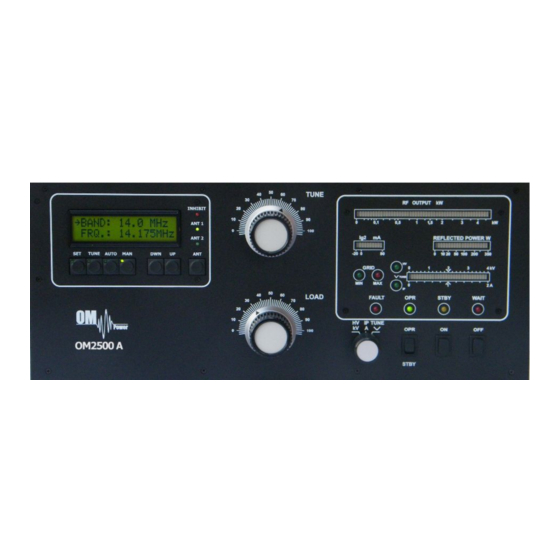
Operation Operating elements (see photo) TUNE - Anode capacitor for tuning, tuning of higher frequencies to "0", Lower frequencies to „100“. LOAD Output capacitor tunes antenna load resistance to amplifier. Capacity is low at „100“ and high at "0" on the scale. OFF - You switch off the amplifier by pressing this button. - Page 11 INHIBIT – indicates interruption of operation during the tuning process of the PA. If indicated by RED LED then PA is in STBY mode. If retuning within same BAND then PA will retune according to QRG of TRX. When changing the BAND –...
- Page 12 Example of AUTO mode using ICOM TRX Example of AUTO mode using Kenwood TRX...
- Page 13 For communication with TCVRs , that are not supported by OM2500A as for example JST-245 and older types of Kenwood an external IF-232 converter is to be used. You can use universal products of microHAM https://www.microham.com as MKII, MK2R+ etc., which process information about the frequency in ICOM format through the CI-V output.
- Page 14 TRX support settings Press SET button and scroll using UP / DWN to CHOOSE TCVR Confirm CHOOSE TCVR by pressing SET again and scroll UP / DWN to desired TRX Type. Confirm the selection by pressing SET Continue by selecting Baud Rate Below –...
- Page 15 Example of connection for Icom...
- Page 16 Example of connection for ELECRAFT...
- Page 17 Example of connection with Yeasu...
- Page 18 Antenna Switching Menu If you have 3 party external antenna switch connected to PA ( i.e. Microham TEN SWITCH) you need to configure assignment of each port to specific band/antenna. By pressing SET and scrolling to ANTENNA SETTINGS and confirming by SET you get current band and its antenna selection.
- Page 19 Example of connection with antenna switch and BPF...
- Page 20 Bandpass filter switching Switching of external band pass filters is automatic and needs to follow pin out of BPF connector. For more see section ANT & BPF Switching Loading factory default settings In rare case of need to restore factory default settings press SET and scroll using UP / DWN to LOAD DEF VALUES and confirm by SET.
- Page 21 Example for connection with another accessories , for example USB micro KEYER II with IC7800 and IC7700...
- Page 22 Example for connection with another accessories , for example USB micro KEYER II with another Icom’s...
- Page 23 Example for connection with another accessories , for example USB micro KEYER II with Yeasu and ELECRAFT...
-
Page 24: Example Of Connection Pa With Microham Mkii, (Mk2R+ Etc ) With Ci-V Output
Example of connection PA with Microham MKII, (MK2R+ etc ) with CI-V output... - Page 25 Configuring the MUTE option When operating PA with Icom TRX without TX INHIBIT for disabling TX we recommend blocking of the TX while tuning using ALC control.(mainly while operating FM /RTTY/ AM) ALC Input of your TRX needs to be connected to ALC Out of OM2500A. Using SET and scrolling UP / DWN we select SET MUTE and confirm it by SET.
- Page 26 To enter Manual mode of the PA please press MAN. By pressing MAN repeatedly you select BAND and band’s segment You can control the segment or band by scrolling the UP / DWN buttons. TUNE OM2500A has been design to deliver maximum output power at 50 Ohms load. To deliver maximum output to real load you need to adjust the tuning according to your real antenna impedance.
- Page 27 The grid-current is shown with 2 LED diodes. It’s normal if the green LED is flashing or may be shining a little bit during peak operation. If you overload the amplifier the output power increases the grid current at very small rates and the red GRID-MAX-LED is shining and the safety devices switch the PA to STBY.
- Page 28 Please note! If the input power is higher than 15 W and the power amplifier is not correctly tuned, the safety devices will switch to STBY. After switching the amplifier to PTT, the amplifier will automatically reset and switch back to OPR mode after approximately 2 seconds.
-
Page 29: Indication Of Fault Conditions
HV + IP - tuning fault, incorrect tuning of the Pi-L output circuit In case your OM2500A amplifier is not working correctly, please contact the manufacturer or your distributor, Manufacturer’s contacts: OM POWER, s.r.o. 930 30 Báč 126 SLOVAKIA e-mail:...
Need help?
Do you have a question about the OM2500 A and is the answer not in the manual?
Questions and answers