Table of Contents
Advertisement
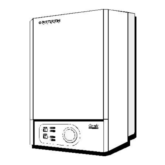
Combi 80 Installation & Service Instructions
About the Boiler
About Safety
See inside cover for models covered by these instructions.
This is a wall mounted, fanned, room sealed combination boiler.
This boiler is for use with Natural Gas (G20) Only at 20 mbar and for use in GB & IE.
The Gas Safety (Installation and Use) Regulations 1998.
''In your own interest, and that of safety, it is law that all gas appliances are installed by
competent persons, in accordance with the above regulations. Failure to install
appliances correctly could lead to prosecution.''
Installation must be in accordance with the User, Installation & Servicing Instructions and
the rules in force.
Polythene bags used for packaging are a potential hazard to babies and young children
and MUST BE CAREFULLY DISPOSED OF IMMEDIATELY.
Leave these instructions with the user for use on future calls.
Advertisement
Table of Contents

Related Manuals for Potterton Combi 80


Summary of Contents for Potterton Combi 80
- Page 1 Combi 80 Installation & Service Instructions About the Boiler See inside cover for models covered by these instructions. This is a wall mounted, fanned, room sealed combination boiler. This boiler is for use with Natural Gas (G20) Only at 20 mbar and for use in GB & IE.
-
Page 2: Table Of Contents
4.7 To Inspect and Clean the Boiler ......22 4.8 To Remove the Burner ........24 4.9 Gas Pressure Adjustment ........24 4.10 The Central Heating Sealed System ....24 4.11 Other Components ..........24 The model covered by these instructions is:- Combi 80 G.C. No. 47-393-03... -
Page 3: Introduction
5546, BS. 5440:1, BS. 5440:2, BS 7593 & BG. DM2. domestic hot water supply. • Samples of the Combi 80 combination boiler have been Domestic Hot Water: Domestic hot water has priority examined by Gastec, a Netherlands Notified Body. The... - Page 4 Introduction - Page 4 Delivery to arise following harsh abrasion. In general, normal handling and use will not present high risk, follow good • hygiene practices, wash hands before, touching eyes, The boiler is delivered in two packages (1) the boiler and consuming food, drinking or using the toilet.
-
Page 5: Installation Requirements
1. Installation Requirements - Page 5 • General Information THIS APPLIANCE MUST BE EARTHED. • • Both the user and the manufacturer rely heavily on the The method of connection to the mains electricity supply installer, whose job it is to install the combination boiler, must provide means of completely isolating the electrical and connect it to a correctly designed heating system. - Page 6 Installation Requirements - Page 6 Fig 3...
-
Page 7: Location Of Boiler
Installation Requirements - Page 7 Location Of Boiler expansion vessel, without removing the appliance from the wall, if replacement is required. • In siting the combination boiler, the following limitations, Bottom Clearance: A bottom clearance of 220 mm is MUST be observed: required between the appliance and any surface. - Page 8 Installation Requirements - Page 8 • 135° Off-set kits are available for both concentric and twin tube. • A Pitched Roof Flashing kit and Flat Roof Flashing kit are available for use with the vertical flue systems. • If a horizontal flue is sited less than 2 metres above a balcony, above ground, or above a flat roof to which people have access, a suitable terminal guard must be fitted.
-
Page 9: Installation To An Existing System
Installation Requirements - Page 9 • Installation to an Existing Central Heating The installation should be designed to work with flow temperatures of up to 90 °C. All components of the System system must be suitable for a maximum pressure of 3 bar (45 psi) and a temperature of 110 °C. - Page 10 Installation Requirements - Page 10 Safety Valve Setting (bar) Initial System Pressure (bar) Total Water Content of System VESSEL VOLUME (L) Fig 6 litres litres litres 11.7 10.9 15.6 13.6 19.5 16.3 23.4 19.1 27.3 21.8 31.2 24.5 35.1 27.2 39.0 30.0 42.9...
- Page 11 Installation Requirements - Page 11 • "Material and Installation Specifications for Domestic Frost Protection Central Heating and Hot Water". The appliance is fitted with an internal frost thermostat, • Pump Performance Curve however this device is purely for the protection of the appliance.
- Page 12 Installation Requirements - Page 12 • Inhibitors For more information regarding cleansers and inhibitors, contact: When the heating system has been completed, it should be cleaned thoroughly in accordance with BS 7593 BetzDearborn Ltd. (code of practice for Treatment of Water in Domestic Hot Widnes, Cheshire.
-
Page 13: Boiler Installation
2. Installation - Page 13 • 7. Boiler Connections: All connections to the appliance are It is MOST IMPORTANT that the appliance is installed supplied unassembled in the boiler carton on a vacuum in a VERTICAL POSITION, with the flue system passing formed card. -
Page 14: Supply
Installation - Page 14 3. Connect the cold water supply to the 15 mm isolating 2. Connect the central heating return pipe to the isolating cock. cock identified by a Blue lever. (right hand of the two pipes) 4. Connect the hot water outlet pipe using a 15 mm compression fitting. -
Page 15: Wiring The Appliance
Installation - Page 15 Wiring the Appliance 3. Check all wiring and reposition the control panel. 4. Secure with screw provided. The wiring diagram is located on the inside of the front Note: The electrical mains supply must be fused at 3 A, casing panel. -
Page 16: Commissioning
3. Commissioning - Page 16 Electrical Installation Gas Installation Conduct a preliminary electrical test by checking: for short The whole of the gas installation including the meter, should circuits, fuse failure, incorrect polarity, earth continuity and be inspected and tested for soundness and purged in resistance to earth. -
Page 17: Initial Lighting
Commissioning - Page 17 Initial Lighting venting of the bearings be required, sideways pressure should be applied and maintained to the knob until a small amount of water becomes visible. The manual WARNING: restart knob should now be screwed back to its original Before operating the appliance, check that the air box position, finger tight. -
Page 18: Gas Pressure Adjustment
Commissioning - Page 18 14. Fully open all domestic hot water outlets, vent flexible Adjusting the Maximum Pressure - Fig. 12. hose connections to the washing machine and dishwasher. Remove air from the domestic hot water Cut off cable tie retaining modulator Cover. distribution system. -
Page 19: Flow Rate
Commissioning - Page 19 D.H.W Flow Rate Appliance Protection Devices • The appliance contains an automatic flow regulator Loss of gas supply, flame failure, or over-heating of the supplying a nominal flow rate of 7.6 litres/minute. This central heating water will cause the appliance to shut flow rate will give a nominal temperature rise of 45°C. -
Page 20: Complete The Installation
Commissioning - Page 20 Complete the Installation • After completion of installation and commissioning of the system re-fit the white front case. • The installer should hand over to the User by the following actions: 1. Explain to the Householder where to find the User's Guide and his/her responsibilities under the 'Gas Safety (Installation and Use) Regulations 1994. -
Page 21: Servicing & Routine Maintenance
4. Servicing & Routine Maintenance - Page 21 • To ensure the continued safe and efficient operation of the appliance it is recommended that it is checked and serviced as necessary at regular intervals. The frequency of servicing will depend upon the particular installation conditions and usage but in general, once per year should be adequate. -
Page 22: Remove The White Front Case
Servicing & Routine Maintenance - Page 22 Remove the White Front Case To Inspect and Clean the Boiler - Fig. 14 1. Remove the two securing screws located at the base of 1. Inspect the heat exchanger for any blockage. Deposits the white front case assembly. - Page 23 Servicing & Routine Maintenance - Page 23...
-
Page 24: To Remove The Burner
(14.5 lb/in) or marginally greater than the designed panel. Further washers can be purchased from system pressure at the appliance when cold, which ever Potterton, Part No.13-18693. If the boiler has been is higher. operating, care must be taken to avoid contact with any hot pipework on the underside of the appliance, during 2. - Page 25 Servicing & Routine Maintenance - Page 25...
-
Page 26: Replacement Of Parts
5. Replacement of Parts - Page 26 WARNING: Before attempting to remove any component from this appliance, first disconnect the mains electricity supply by removing the plug from the wall socket or by switching off the appliance at the external isolating switch. Note: The appliance stand-by switch must not be used as the means of isolating, as this switch does leave parts of the appliance electrically live. -
Page 27: Central Heating Overheat Thermostat
Replacement of Parts - Page 27 Central Heating Overheat Thermostat Sensor and Ignition Electrode Fig. 17 1. Remove the white front case, base panel, air box covers 1. Remove the white front case and three air box covers. and combustion chamber front panel. See 4.1 to 4.3 & See 4.1 &... -
Page 28: Gas Valve
Replacement of Parts - Page 28 Gas Valve 5.10 Second Solenoid Valve - Fig. 18 1. Remove the white front case, base panel & white left 1. Remove the white front case. hand side panel. See 4.1 in 'Routine Maintenance'. See 4.1, 4.2 &... - Page 29 Replacement of Parts - Page 29 Fig 18...
-
Page 30: Central Heating And Boiler Switch
Replacement of Parts - Page 30 Fig 19 USER DISPLAY BOARD Undo the fixing screw retaining the facia panel and 5.12 Central Heating and Boiler Switches swing the panel downwards. Remove the plug connector/s from the rear of the board 1. -
Page 31: Air Pressure Switch
Replacement of Parts - Page 31 5.14 Air Pressure Switch 5.15 - Fig. 11 & 20 1. Remove the white front case, base panel and white right 1. Remove the fan. See 4.1, 4.2 & 4.3in ‘Routine hand side panel. See 4.1, 4.2 & 4.3 in 'Routine Maintenance’. -
Page 32: Water Flow Switch D.h.w
Replacement of Parts - Page 32 5.19 Water Flow Switch (D.H.W.) 5.21 Pump - Fig. 16 1. Remove the white front case and base panel. For ease of replacement it is advisable to fit a new motor See 4.1 & 4.2in ’Routine Maintenance’. (head) assembly to the existing pump housing. -
Page 33: Diverter Valve
Replacement of Parts - Page 33 5.22 Diverter Valve - Fig. 22 The diverter valve is made up in two parts. The wax capsule head forms one part and provides the motive power to open the valve. The second part, the valve consists of the change over mechanism and the valve seating. -
Page 34: Expansion Vessel C.h
Replacement of Parts - Page 34 5.23 Expansion Vessel C.H. Procedure 2 If the clearance above the appliance is less than 300 mm In the unlikely event of a failure of the C.H. expansion vessel the appliance must be removed from the wall. it is recommended that a new vessel be fitted exterior to the boiler. -
Page 35: Expansion Vessel D.h.w
Replacement of Parts - Page 35 5.24 Expansion Vessel D.H.W. - Fig. 23 Isolate the electrical supply prior to this operation. 1. Remove the white front case and base panel. See 4.1 & 4.2in ’Routine Maintenance’. 2. Lower the control panel assembly by undoing the securing screw at the top right hand side of the control panel. -
Page 36: Automatic Air Vent
Replacement of Parts - Page 36 5.26 Automatic Air Vent - Fig. 24 1. Remove the white front case, base panel and white left hand side panel. See 4.1, 4.2 & 4.3 in 'Routine Maintenance'. 2. Drain the central heating circuit as described on Page 3. -
Page 37: Transformer Assembly
Replacement of Parts - Page 37 5.28 Transformer Assembly - Fig. 26 1. Remove the white front case and base panel. See 4.1 & 4.2 in ’Routine Maintenance’. 2. Lower the control panel assembly by undoing the securing screw at the top right hand side of the control panel. -
Page 38: Fault Finding
6. Fault Finding - Page 38 Preliminary Actions: a. Set Boiler Switch to Standby. - b. Set Heating switch to ‘OFF’ (Centre) - c. Turn OFF all Hot Water Taps - d. Ensure all Isolating Valves at base of appliance are OPEN e. -
Page 39: Electrical Layouts
7. Electrical Layouts - Page 39 Control Flow Sequence... -
Page 40: Functional Flow
Functional Flow - Page 40... -
Page 41: Electrical Diagram
Electrical Diagram - Page 41... -
Page 42: Product Specification
8. Product Specification - Page 42 Heat Input: Max. 30.0 kW(102,350 Btu/h) Range Rate (C.H. Only) 22.5 kW(76,760 Btu/h) Min. 14.4 kW(49,130 Btu/h) Heat Output: Max. 24.0 kW(81,880 Btu/h) Range Rate (C.H. Only) 17.2 kW(58,680 Btu/h) Min. 10.4 kW(35,480 Btu/h) Gas Rate Full 2.86 m³/hr... -
Page 43: Optional Extras
9. Optional Extras - Page 43... - Page 44 Optional Extras - Page 44...
- Page 45 Optional Extras - Page 45...
-
Page 46: Short List Of Spares
10. Short List of Spares - Page 46... - Page 47 Short List of Spares - Page 47 Item Description Potterton G.C. Part No. Part No. Modulation Control Board 929686 289 551 Display Board 21/20761 Full Sequence Control Board 929689 289 555 Pump Kit (Myson Compact) 929636 289 730 Main Burner Assembly...
Need help?
Do you have a question about the Combi 80 and is the answer not in the manual?
Questions and answers