
Related Manuals for Vega VEGADIS 363


Summary of Contents for Vega VEGADIS 363
-
Page 1: Operating Instructions
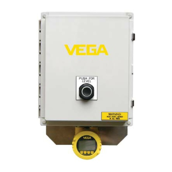
Operating Instructions VEGADIS 363 Remote Display Unit Document ID: 44054 Indication and Adjustment... -
Page 3: Revision History Of Manual
121128 Converted to A5 Format 131121 This document contains proprietary information of VEGA Americas, Inc. It shall not be reproduced in whole or in part, in any form, without the expressed written permission of VEGA Americas, Inc. The material in this document is provided for informational purposes and is subject to change without notice. - Page 4 NOTES 44054-131121-US...
-
Page 5: Table Of Contents
PACTware Software Startup - - - - - - - - - - - - - - - - - - - - - - - - - - - - - - -10 Set up Project Tree with VEGA Project Assistant - - - - - - - - - - - - - - - -10 System Battery . - Page 6 6 Supplemental Information ......51 VEGADIS 363 Field Checklist ......51 VEGADIS 363 Advanced Service Checklist* .
-
Page 7: Remote Display System
1.2 System Operation The VEGA level measurement device, in combination with the RD, provide the level information to the Remote Display. Each RD can handle one (1) VEGA, 2- wire HART device. The Remote Display interface can display level, percent (%), scaled value, and distance. -
Page 8: Pactwaretm
PACTware™ (Process Automation Configuration Tool) is a protocol-independent software for the adjustment of all types of field instruments. This software is VEGA’s preferred tool for setting up and adjusting the detector. Connection of the PC with VEGACONNECT Use the interface converter VEGACONNECT for a temporary connection of the PC. - Page 9 VEGACONNECT 4 Connection to Radar with Cable Figure 1.1 1. Cable from VEGACONNECT to Radar 2. VEGACONNECT 4 3. USB Cable to PC 4. PC with PACTware software 5. Power Supply 6. Radar VEGACONNECT 4 Connection Radar Only Figure 1.2 1.
-
Page 10: Pactware Software Startup
VEGA DTMs in other frame applications according to the FDT standard. For a connection, either the interface converter VEGACONNECT or a USB is required. A basic understanding of PACTware and VEGA DTMs is required to properly configure the Remote Display Systems. -
Page 11: System Battery
Each system is slightly different and may have more than one device. HOST PC <COM1>VEGA RS232 VEGA CONNECT (I2C) <Device Na <Device Name>VEGASCAN 693 VEGASCAN 693 <0,Sensor>VEGADIS 363 HART VEGACONNECT Project Tree Figure 1.3 1.4 System Battery Indications of low batteries include: • Dim display •... - Page 12 • Dispose of the lithium batteries using approved local methods. The VEGA device stores the configuration data for the RD. When replacing the batteries, configuration settings are still in this memory. To replace batteries (power supply and display boards), complete the following steps: Turn the Source Selector Switch to OFF.
-
Page 13: Radar Configuration With Pactware
PACTware™ (Process Automation Configuration Tool) is a protocol-independent software for the adjustment of all types of field instruments. This software is VEGA’s preferred tool for setting up and adjusting the device. Change Multidrop Address If multidrop addresses are not set, you must connect to each device’s I connection independently. - Page 14 In the Modify address in the instrument: Step 1 dialog box, click Multidrop. Multidrop Option Figure 2.2 In the Address list, click one (1). Address Range List Figure 2.3 Click Apply to change the sensor to HART Multidrop mode operating at 4 44054-US-131121...
-
Page 15: Change Measurement Loop Name
The measurement loop name is a unique identifier (16 characters maximum). If the name is provided at the time of your order, the parameter was entered at VEGA prior to shipment. If the name was not provided, type the measurement loop name (16 characters is the maximum) in the Measurement loop name box. -
Page 16: Adjust Min. Max. Levels
Adjust Min. Max. Levels Click the plus (+) symbol next to the Setup parameter menu to expand the menu. Click the Min-Max adjustment parameter submenu. Min./Max. Adjustment Figure 2.5 Type the maximum adjustment in the Max. adjustment in percent box. Type the distance in the Distance A (max. -
Page 17: Application
Click Apply. Application Your sensor ships from VEGA with default factory settings. You should change the application your sensor is set to measure with the following steps: Click the plus (+) symbol next to the Setup parameter menu to expand the menu. -
Page 18: False Signal Suppression
Click Apply. Application Figure 2.6 False Signal Suppression False signal suppression stores the false echoes in memory from the reference plane of the sensor to the actual distance of the product surface. Struts, weld seams, agitators, man-ways, internal ladders, or anything that causes a reflection of the radar or ultrasonic pulse results in false echoes. -
Page 19: Perform False Signal Suppression
Perform False Signal Suppression Create New Click the plus (+) symbol next to the Additional settings parameter menu to expand the menu. Click False signal suppression. From the Activity to be carried out list, click Create new. In the Sounded distance box, type the distance to the bottom of the tank. Click Execute. - Page 20 From the Activity to be carried out list, click Update. In the Sounded distance box, type the distance to the current level of the liquid being measured. Click Execute. False Signal Suppression Update Figure 2.8 Note: The Sounded distance or new level to the bottom of the tank is 5.0 feet.
-
Page 21: Manual Edit False Signal Suppression
Manual Edit False Signal Suppression Manually edit the false signal suppression with the following steps. Click the plus (+) symbol next to the Additional settings parameter menu to expand the menu. Click plus (+) symbol next to False signal suppression parameter submenu to expand the menu. - Page 22 Note: If there is condensate at the end of the horn or antenna, add a manually edit the false signal to compensate for this condition. NOTE Manually Edited False Signal Figure 2.11 44054-US-131121...
-
Page 23: Radar Configuration With Plicscom
3 Radar Configuration with PLICSCOM 3.1 Overview PLICSCOM is the indicating and adjustment unit for VEGA PLICS sensors. The following sections contain information primarily as an aid in setting basic sensor parameters. Follow the required basic parameters for new instrument setup in the order depicted. -
Page 24: Plicscom Features
VEGACONNECT, for a temporary connect of the PC for the adjustment of many types of field instruments. This software is VEGA’s preferred tool for parmeterization and customization of PLICS sensors where some adjustments are beyond the capabilities of the PLICSCOM. - Page 25 1. PACTware Software 2. VEGACONNECT 4 3. VEGACONNECT 4 Open 44054-US-131121...
-
Page 26: Min. Adjustment
3.5 Min. Adjustment Step 1 Step 2 Step 3 TWIST TWIST TWIST Setup 3.800 Setup Vessel height/Me.range Display Max. adjustment Diagnostics Min. adjustment Additional adjustments Damping Info Current output mode Sensor ▼ From Main display, press OK Press OK again to access the Setup submenu. Use arrow to move through Setup submenus. -
Page 27: Max. Adjustment
3.6 Max. Adjustment Step 1 Step 2 Step 3 TWIST TWIST TWIST Setup 3.800 Setup Vessel height/Me.range Display Max. adjustment Diagnostics Min. adjustment Additional adjustments Damping Info Current output mode Sensor ▼ From Main display, press OK Press OK again to access the Setup submenu. Use arrow to move through Setup submenus. -
Page 28: Applications Liquids Setup
3.7 Applications Liquids Setup Step 1 Step 2 Step 3 TWIST TWIST TWIST Setup 3.800 Setup Measurement loop name Display Medium Diagnostics Application Additional adjustments Vessel type Info Vessel height/Me. range Sensor ▼ From Main display, press OK Press OK again to access the Setup submenu. Use arrow to move through Setup submenus. -
Page 29: Application
3.8 Application Step 1 Step 2 Step 3 TWIST TWIST TWIST Setup Setup 3.800 Measurement loop name Display Medium Diagnostics Application Additional adjustments Vessel type Info Vessel height/Me. range Sensor ▼ From Main display, press OK Press OK again to access the Setup submenu. Use arrow to move through Setup submenus. -
Page 30: Applications Solids Setup
3.9 Applications Solids Setup Step 1 Step 2 Step 3 TWIST TWIST TWIST Setup Setup 3.800 Display Measurement loop name Medium Diagnostics Application Additional adjustments Vessel type Info Vessel height/Me. range Sensor ▼ From Main display, press OK Press OK again to access the Setup submenu. Use arrow to move through Setup submenus. -
Page 31: Applications Damping Setup
3.10Applications Damping Setup Step 1 Step 2 Step 3 TWIST TWIST TWIST Setup Setup 3.800 Max. adjustment Display Min. adjustment Diagnostics Damping Additional adjustments Current output mode Info Current output min./max. Sensor ▼ From Main display, press OK Press OK again to access the Setup submenu. Use arrow to move through Setup submenus. -
Page 32: Applications Linearization Curve Setup
3.11Applications Linearization Curve Setup Step 2 Step 3 Step 1 TWIST TWIST TWIST Setup Setup 3.800 Display Display Diagnostics Diagnostics Additional adjustments Additional adjustments Info Info Sensor From Main display, press OK Use the arrow to move through the menus. Press OK to access Additional adjustments. -
Page 33: Measurement Loop Name
3.12Measurement loop name Step 1 Step 2 Step 3 TWIST TWIST TWIST Setup Setup 3.800 Measurement loop name Display Date/Time Diagnostics Reset Additional adjustments Info Date/Time Sensor ▼ Press OK to select Measurement loop name From Main display, press OK Press OK to access Setup. -
Page 34: False Signal Suppression
3.13False Signal Suppression Step 2 Step 3 Step 1 TWIST TWIST TWIST Setup Setup 3.800 Display Display Diagnostics Diagnostics Additional adjustments Additional adjustments Info Info Sensor From Main display, press OK Use the arrow to move through the menus. Press OK to access Additional adjustments. to access the submenus. -
Page 35: Units Of Measurement
3.14Units of Measurement Step 1 Step 2 Step 3 TWIST TWIST TWIST Setup Setup 3.800 Display Display Diagnostics Diagnostics Additional adjustments Additional adjustments Info Info Sensor Press OK to access Additional adjustments. From main display, press OK Use the arrow to move through the menus. to access submenus. -
Page 36: Hart Address Setup
3.15HART Address Setup Step 1 Step 2 Step 3 TWIST TWIST TWIST Setup Setup 3.800 Display Display Diagnostics Diagnostics Additional adjustments Additional adjustments Info Info Sensor Press OK to access Additional adjustments. From Main display, press OK Press OK again to access the Setup submenu. to access the submenus. -
Page 37: Reset Gauge
3.16Reset Gauge Step 1 Step 2 Step 3 TWIST TWIST TWIST Setup Setup 3.800 Display Display Diagnostics Diagnostics Additional adjustments Additional adjustments Info Info Sensor Press OK to access Additional adjustments. Use the arrow to move through the menus. From Main display, press OK to access submenus. -
Page 38: Reset Setup
Reset Setup All parameters of the adjustment level setup aer reset to the standard delivery status. Reset Linearization An entered “user programmable” linearization curve is deleted and the setting “linearization” is reset to “linear”. Reset Measured Value Memory An active measured value recording in the instrument is stopped and already saved measured values are deleted. -
Page 39: Rd Installation Diagrams
4 RD Installation Diagrams The Remote Display System is pre-configured by VEGA. Make certain the radars are installed and wired as configured from the factory. This following items provide the general guidelines for the correct installation of your RDs. 4.1 RD Enclosure Views 1.52"... - Page 40 5.85" [148 mm] Enclosure-Side View Figure 4.2 44054-US-131121...
-
Page 41: Typical Installation Wiring
4.2 Typical Installation Wiring REMOTE MOUNTED PULS60 SERIES RADAR WIRING DIAGRAM FOR LAPTOP CONNECTION SECTION - CC - RADAR TO DISPLAY WIRING 2-WIRE SETUP REMOTE TB-1 DISPLAY Radar Wiring in PULS Housing 1 - Brown TO TDR (T-3) 1 - Brown 5 - Blue 2 - White 6 - Yellow... -
Page 42: Rd Inside Panel - External Power Source Option
Note: Set the Rotary Switch timing range to “G” for 0.1 to 10 minutes off delay. NOTE 4.4 RD Inside Panel - External Power Source Option VEGATREN 149A TB-1 RD Inside Panel - External Power Source Option Figure 4.5 44054-US-131121... -
Page 43: Rd Electrical Schematic- Battery Only (Standard)
4.5 RD Electrical Schematic- Battery Only (Standard) DELAY_ON_DROP_OUT_RELAY_TIMER FROM INTERNAL BATTERY POWER SUPPLY (28VDC) F1-TDR SEE SECTION BB FOR BATTERY WIRING DETAILS SET ROTARY SWITCH TIMING BATTERY PNL RANGE TO "G" FOR 0.1 TO 10 MINUTE OFF DELAY +VDC PS24+ FROM LINE 113 0.25A PS124-... -
Page 44: Rd Electrical Schematic - External Power Source Option
4.6 RD Electrical Schematic - External Power Source Option DELAY_ON_DROP_OUT_RELAY_TIMER FROM INTERNAL BATTERY POWER SUPPLY (28VDC) F1-TDR SEE SECTION BB FOR BATTERY WIRING DETAILS SET ROTARY SWITCH TIMING BATTERY PNL OFF BATTERY EXTERNAL RANGE TO "G" FOR PS24+ +VDC PS24+ 0.1 TO 10 MINUTE OFF DELAY FROM LINE 113 0.25A... -
Page 45: Radar To Display Wiring
4.7 Radar to Display Wiring REMOTE MOUNTED PULS60 SERIES RADAR WIRING DIAGRAM FOR LAPTOP CONNECTION 2-WIRE SETUP SECTION - CC - RADAR TO DISPLAY WIRING REMOTE TB-1 DISPLAY Radar Wiring in PULS Housing 1 - Brown TO TDR (T-3) 1 - Brown 5 - Blue 2 - White 2 - White... -
Page 46: Power Source Selector Switch
Power Source Selector Switch Name Specification Usage Universal line power supply 20 - 230 volts AC/DC Line AC power or high voltage DC (not loop power), Solar Panel, External Battery Internal battery power supply 14.4 - 28.8 volts DC Internal batteries AA 3.6 volt Lithium RD Wiring for AC and DC Power Before beginning any wiring, make certain you use wire that meets the local... -
Page 47: Rd Battery Type
should last for over two (2) years. This estimated life for these batteries is based on 30 minutes of use per day. Note: Change all eight (8) batteries at the same time for optimum performance. NOTE The RD manages the power to the loop powered sensor to maximize battery life. RD Battery Type The following two (2) approved battery types have a temperature rating for the full operating temperature range of the RD. - Page 48 • Dispose of the lithium batteries using approved local WARNING methods. The VEGA device stores the configuration data for the RD. When replacing the batteries, configuration settings are still in this memory. To replace batteries (power supply and display boards), complete the following steps: If the RD is mounted in a hazardous location, take it to a non-hazardous location.
-
Page 49: Customer Service
4.9 Customer Service VEGA has Field Service Engineers available for onsite service, emergency services, or equipment start up Description Telephone Number Tel (Monday – Friday 8:00 A.M. – 5:00 P.M. EST) +1 513-272-0131 Tel (emergencies: follow the voice mail instructions) - Page 50 NOTES 44054-US-131121...
-
Page 51: Supplemental Information
5 Supplemental Information VEGADIS 363 Field Checklist Inspect wiring, enclosure, quick-connects & radar for defects Check for lose wires in Radar, Display & at enclosure terminals Check fuses in place for blown fuse Remove and re-install display for tight connection... -
Page 52: Vegadis 363 Advanced Service Checklist
VEGADIS 363 Advanced Service Checklist* Check DC voltage at T1(+) & T2(-) for 28 to 30 VDC Remove batteries from holder & check each battery for 3.6 Press push button for Level and check DC voltage at terminals 1(+) & 2(-) for 28 to 30 VDC Continuity check from Radar connections 1,2,5,6,7,8 to both sides of terminals 1,2,5,6,7,8 &... - Page 53 If damaged, return for repair to VEGADIS 363 Service or VEGA Service Check for crack on relay base or broken pins on the relay Check for proper polarity installation on batteries Turn off relay and reset the radar power Turn reset the radar power ON-TIME Press and hold level push button for 5 seconds 10.
-
Page 54: Vegadis 363 Advanced Service Troubleshooting Tips
If battery voltage is not 3.6VDC (+/- 5%) replace batteries If no voltage at terminals 1(+) & 2(-) check or replace relay Check for proper terminations of wire under screw terminals (no insulation under terms) If box still does not work, send to VEGA service for repair 44054-US-131121... - Page 56 All statements concerning scope of delivery, application, practical use, and operating conditions of the sensors and processing systems correspond to the information available at the time of printing. 2013 VEGA Americas, Inc. Cincinnati, Ohio, USA © Subject to change without prior notice 44054-US-131121...
Need help?
Do you have a question about the VEGADIS 363 and is the answer not in the manual?
Questions and answers