
Related Manuals for Mitsubishi Electric City Multi PFFY-P20VLRMM-E


Summary of Contents for Mitsubishi Electric City Multi PFFY-P20VLRMM-E
- Page 1 2007 Air-Conditioners TECHNICAL & SERVICE MANUAL PFFY-P20VLRMM-E, PFFY-P40VLRMM-E Models PFFY-P25VLRMM-E, PFFY-P50VLRMM-E PFFY-P32VLRMM-E, PFFY-P63VLRMM-E For use with the R410A...
-
Page 2: Safety Precautions
Safety Precautions Read before installation and performing electrical work Thoroughly read the following safety precautions prior to installation. Observe these safety precautions for your safety. This equipment may have adverse effects on the equipment on the same power supply system. Contact the local power authority before connecting to the system. - Page 3 When installing the unit in a small space, take appropriate mended by Mitsubishi Electric may result in smoke, fire, or precautions to prevent leaked refrigerant from reaching the explosion.
-
Page 4: Table Of Contents
CONTENTS I Features [1] Features............................ 1 II Components and Functions [1] Components and Functions...................... 2 III Specfications [1] Specifications..........................4 1.Specfications .......................... 4 2.Electrical component specifications..................6 IV Outlines and Dimensions [1] Outlines and Dimensions......................7 V Wiring Diagram [1] Wiring Diagram ......................... 8 VI Refrigerant System Diagram [1] Refrigerant system diagram.................... - Page 5 HWE07170...
-
Page 6: Features
[ I Features ] I Features [1] Features Model Cooling capacity/Heating capacity PFFY-P20VLRMM-E 2.2/2.5 PFFY-P25VLRMM-E 2.8/3.2 PFFY-P32VLRMM-E 3.6/4.0 PFFY-P40VLRMM-E 4.5/5.0 PFFY-P50VLRMM-E 5.6/6.3 PFFY-P63VLRMM-E 7.1/8.0 - 1 - HWE07170... -
Page 7: Components And Functions
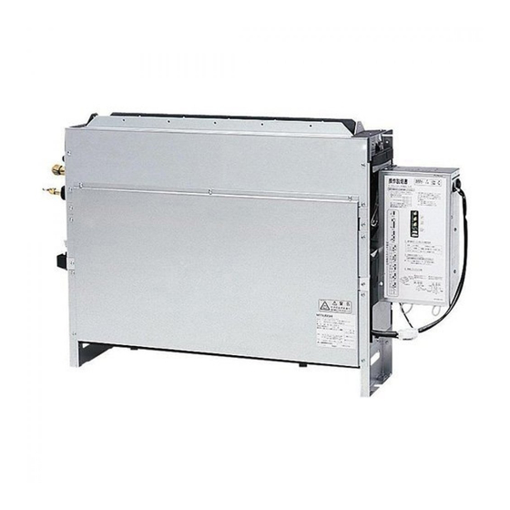
[ II Components and Functions ] II Components and Functions [1] Components and Functions 1. Indoor (Main) Unit 2. Remote Controller [PAR-21MAA] Once the operation mode is selected, the unit will remain in the selected mode until changed. (1) Remote Controller Buttons [Set Temperature] Button [Vane Control] Button [Timer Menu] Button... - Page 8 [ II Components and Functions ] (2) Remote Controller Display Current time/Timer time Louver swing Centralized control indicator Ventilation Timer OFF indicator Filter sign Timer mode Sensor position Operation mode display: COOL, DRY, AUTO, Room temperature FAN, HEAT Function Lock indicator Vane setting Preset temperature Fan speed...
-
Page 9: Specfications
[ III Specfications ] III Specfications [1] Specifications 1. Specfications Model PFFY- PFFY- PFFY- P20VLRMM-E P25VLRMM-E P32VLRMM-E Power supply Voltage 220-240 Frequency 50/60 Cooling capacity Heating capacity Power consumption Cooling 0.04/0.04 0.04/0.04 0.04/0.04 Heating 0.04/0.04 0.04/0.04 0.04/0.04 Current consumption Cooling 0.34/0.33 0.34/0.33 0.38/0.37... - Page 10 [ III Specfications ] Model PFFY- PFFY- PFFY- P40VLRMM-E P50VLRMM-E P63VLRMM-E Power supply Voltage 220-240 Frequency 50/60 Cooling capacity Heating capacity Power consumption Cooling 0.05/0.05 0.05/0.05 0.07/0.07 Heating 0.05/0.05 0.05/0.05 0.07/0.07 Current consumption Cooling 0.43/0.42 0.48/0.47 0.59/0.58 Heating 0.43/0.42 0.48/0.47 0.59/0.58 External finish (Munsel No.) Galvanized steel plate...
-
Page 11: Electrical Component Specifications
[ III Specfications ] 2. Electrical component specifications Component Sym- PFFY-P20VLRMM-E PFFY-P25VLRMM-E PFFY-P32VLRMM-E Room temperature TH21 Resistance 0°C/15k , 10°C/9.6k , 20°C/6.3k , 25°C/5.4k , 30°C/4.3k , 40°C/3.0k thermistor Liquid pipe thermistor TH22 Resistance 0°C/15k , 10°C/9.6k , 20°C/6.3k , 25°C/5.4k , 30°C/4.3k , 40°C/3.0k Gas pipe thermistor TH23 Resistance 0°C/15k , 10°C/9.6k , 20°C/6.3k , 25°C/5.4k , 30°C/4.3k , 40°C/3.0k... -
Page 12: Outlines And Dimensions
[ IV Outlines and Dimensions ] IV Outlines and Dimensions [1] Outlines and Dimensions 1. PFFY-P20, 25, 32, 40, 50, 63VLRMM-E - 7 - HWE07170... -
Page 13: Wiring Diagram
[ V Wiring Diagram ] [1] Wiring Diagram V Wiring Diagram 1. PFFY-P20,25,32,40,50,63VLRMM-E - 8 - HWE07170... - Page 14 [ V Wiring Diagram ] Table.1 SYMBOL EXPLANATION SYM- NAME SYM- NAME SYM- NAME I.B. Indoor control board CN32 Connector (Remote switch) Switch (model setting) (I.B.) A.B. Address board CN41 Connector (HA terminal-A) Connector (emergency opera- (I.B.) tion) Power supply terminal block CN51 Connector (Centralized con- Switch (function setting)
-
Page 15: Refrigerant System Diagram
[ VI Refrigerant System Diagram ] [1] Refrigerant system diagram VI Refrigerant System Diagram Gas pipe thermistor TH23 Gas pipe Liquid pipe Brazed connections Strainer (#100 mesh) Linear expansion valve Liquid pipe thermistor TH22 Heat exchanger Room temperature thermistor TH21 Capacity PFFY-P20, 25, 32, 40, 50VLRMM-E PFFY-P63VLRMM-E... -
Page 16: Troubleshooting
[ VII Troubleshooting ] VII Troubleshooting [1] Troubleshooting 1. Check methods 1. Component and check points (1) Thermistor Room temperature thermistor (TH21) Liquid pipe thermistor (TH22) Gas pipe thermistor (TH23) Disconnect the connector and measure the resistance between terminals with a tester. (Ambient temperature 10°C - 30°C) Normal Abnormal... - Page 17 [ VII Troubleshooting ] 1) Summary of linear expansion valve (LEV) operation The LEV is operated by a stepping motor, which operates by receiving a pulse signal from the indoor control board. The LEV position changes in response to the pulse signal. Indoor control board and LEV connection 12VDC Brown...
- Page 18 [ VII Troubleshooting ] 2) LEV operation Close Open Fully open valve (2000 pulses) No. of pulses Extra tightning (0 - 200 pulse) Valve opening degree When the power is turned on, a pulse signal of 2200 pulses is output (valve closure signal), to bring the valve to position A. When the valve is operating normally, it is free of vibration noise.
- Page 19 [ VII Troubleshooting ] Symptom Checking Criteria Remedy Valve closure fail- To check the LEV on the indoor unit, check the indoor unit liquid pipe temperature Replace the LEV ure (leaky valve) that appears on the operation monitor on the outdoor unit's multi control board while if the amount of operating the indoor unit in question in the FAN mode and the other indoor units in leakage is great.
-
Page 20: Dc Fan Motor (Fan Motor/Indoor Control Board)
[ VII Troubleshooting ] 2. DC fan motor (fan motor/indoor control board) 1. CAUTION A high voltage is applied to the connector for connection to the fan motor (CNMF). Do not unplug the connector CNMF with the unit energized to avoid damage to the indoor control board and fan motor. 2. -
Page 21: Address Switch Setting
[ VII Troubleshooting ] 3. Address switch setting Make sure that power to the unit is turned off. Indoor unit control board Factory setting (all models) 1. When using an ME remote controller, set the address with the rotary switches (SW11, SW12). Address setting is not required when the unit remote controller is used. -
Page 22: Voltage Test Points On The Control Board
[ VII Troubleshooting ] 4. Voltage test points on the control board 1. PFFY-P20, 25, 32, 40, 50, 63VLRMM-E Fuse Fuse(AC 250V 6.3A) Power supply voltage (220 - Fuse 240VAC) CN2M For M-NET transmission cable connection (24 - 30VDC) Emergency operation Capacity setting Function setting CN42... -
Page 23: Dipswitch Setting (Factory Setting)
[ VII Troubleshooting ] 5. Dipswitch setting (Factory setting) 1. Function setting (1) SW1 Switch position Function Switch setting Active Thermistor (Intake air ther- Built-in thermistor on the remote Indoor unit mistor) controller Filter clogging detection Available Unavailable Filter life 2500 hr 100 hr Outdoor air intake... - Page 24 [ VII Troubleshooting ] 2. Capacity code setting (1) SW2 1) Indoor control board Dipswitch settings must be made while the unit is stopped. Factory setting The switches are set to correspond to the unit capacity. PFFY-P20VLRMM-E PFFY-P25VLRMM-E PFFY-P32VLRMM-E PFFY-P40VLRMM-E PFFY-P50VLRMM-E PFFY-P63VLRMM-E 3.
- Page 25 [ VII Troubleshooting ] 5. 1's and 10's digits (1) SW11, SW12 (Rotary switch) The use of a network remote controller (PAR-F27MEA) requires address setting. 1) Address board Address settings must be made while the unit is stopped. Factory setting 6.
-
Page 26: Disassembly Procedure
[ VIII Disassembly Procedure ] VIII Disassembly Procedure [1] Disassembly Procedure 1. Control box Exercise caution when removing heavy parts. 1. Removing the control box cover (1) Remove the fixing screws (two) on the cover (A) to re- move it. - 21 - HWE07170... -
Page 27: Thermistor (Intake Air)
[ VIII Disassembly Procedure ] 2. Thermistor (Intake air) Exercise caution when removing heavy parts. 1. Removing the thermistor (1) Pull out the thermistor holder (B) and thermistor (C) under the control box. - 22 - HWE07170... -
Page 28: Drainpan
[ VIII Disassembly Procedure ] 3. Drainpan Exercise caution when removing heavy parts. 1. Removing the casing ass'y (1) Remove the fixing screws(nine) of the plate(D) and remove the plate. 2. Remove the drainpan cover 3. Remove the drainpan (1) Remove the fixing screw of the both side frame. - 23 - HWE07170... - Page 29 [ VIII Disassembly Procedure ] (2) Remove the magnet plate (G),(H),(I) of the both frame,re- move the tube (J). (3) Slide the drainpan in the direction of the arrow 1. - 24 - HWE07170...
-
Page 30: Thermistor (Gas Pipe) (Liquid Pipe)
[ VIII Disassembly Procedure ] 4. Thermistor (Gas pipe) (Liquid pipe) Exercise caution when removing heavy parts. 1. Removing the thermistor (1) Remove the fixing screws (three),remove the cover (K) and (L). (2) Remove the thermistor (gas)(M) and thermistor(liquid)(N). - 25 - HWE07170... -
Page 31: Fan And Fan Motor
[ VIII Disassembly Procedure ] 5. Fan and fan motor Exercise caution when removing heavy parts. 1. Remove the plate(D) with procedure 3-1. 2. Remove the drainpan with procedure 3-2,3. 3. Sliding the fan section (1) Remove the fixing screws(two). (2) Slide the fan section in direction of the arrow 2. -
Page 32: Heat Exchanger
[ VIII Disassembly Procedure ] 6. Heat exchanger Exercise caution when removing heavy parts. 1. Remove the plate(D) with procedure 3-1. 2. Removng the air diffuser ass'y (1) Remove the fixing screws(eight) of the air diffuser ass'y(P) and remove it. 3. - Page 33 Nov. 2007 HWE07170 New publication, effective Nov. 2007 Printed in Japan Specifications subject to change without notice...