
Related Manuals for Pioneer A-209


Summary of Contents for Pioneer A-209
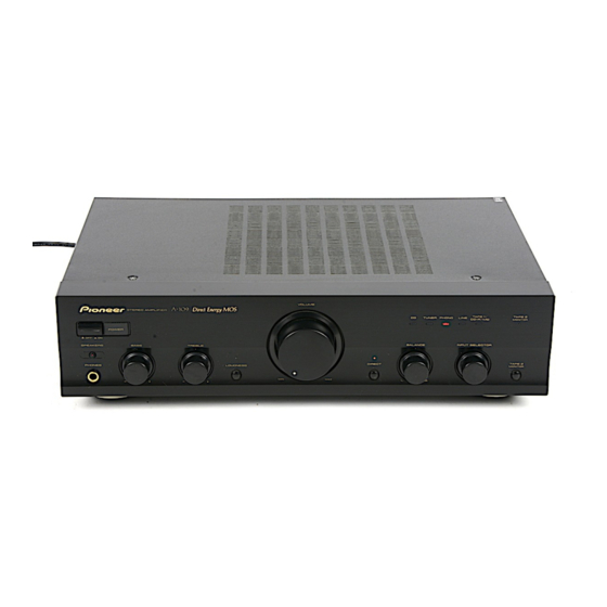
- Page 1 STEREO AMPLIFIER AMPLIFICADOR ESTEREOFONICO A-209 A-109 Operating Instructions Manual de instrucciones...
- Page 2 Operating Environment H045 En Operating environment temperature and humidity: +5°C – +35°C (+41°F – +95°F); less than 85%RH (cooling vents not blocked) Do not install in the following locations ÷ Location exposed to direct sunlight or strong artificial light ÷ Location exposed to high humidity, or poorly ventilated location LINE VOLTAGE SELECTOR SWITCH H038 En...
-
Page 3: Table Of Contents
Thank you for buying this PIONEER product. Please read through these operating instructions so you will know how to operate your model properly. After you have finished reading the instructions, put them away in a safe place for future reference. -
Page 4: Connections
R E C P L A Y P L A Y R E C O U T Left (L) · ª ª · The illustration shows the A-209. SPEAKERS SIGNAL PHONO TUNER LINE TAPE 1/CD-R/MD TAPE 2 MONITOR ª ·... -
Page 5: Connecting The Speaker Cords
Please use the correct cord and plug for your region. Speaker Impedance For regions with two pin flat-bladed plug and 200 volts or [A-209] greater power supply When speaker systems are connected to only SPEAKERS A or SPEAKERS B terminals, such speakers should have rated impedance in the range of 4–16 Ω. -
Page 6: Panel Facilities
DIRECT TAPE 2 MONITOR – – The illustration shows the A-209. POWER (—OFF/_ON) switch TAPE 2 MONITOR button/indicator Press to turn power to the unit ON and OFF. Use when there is an adaptor component (graphic equalizer, etc.) or cassette deck connected to the TAPE 2 MONITOR terminals. - Page 7 DIRECT button/indicator SPEAKERS B (ON/OFF) button/indicator Use this button when you do not wish to pass the output from (A-209 only) input terminal equipment through the various frequency ad- Use this button to listen to the speaker system connected to justing circuits (BASS, TREBLE, BALANCE, LOUDNESS).
- Page 8 · AC INLET PLAY PLAY The illustration shows the A-209. GND (Turntable ground) terminal AC INLET jack Connect one end of the power cord to here and the other end to an AC wall socket, or the AC outlet of an audio timer.
-
Page 9: Operations
2. Set the POWER switch to ON. 3. Press the SPEAKERS button corresponding to the speaker system to be used. (A-209 only) Application examples: ÷ To make a tape copy with contents identical to the original Press the SPEAKERS switch to ON. - Page 10 OPERATIONS TO USE THE COMPONENT CONNECTED TO THE TAPE 2 MONITOR TERMINALS [For a cassette deck] ÷ A cassette deck connected here can be operated in the same way (recording and playback) as a deck connected to the TAPE 2 MONITOR terminals. ÷...
-
Page 11: Troubleshooting
Sometimes the trouble may lie in another component. Investigate the other components and electrical appliances being used. If the trouble cannot be rectified even after exercising the checks listed below, ask your nearest PIONEER authorized service center or your dealer to carry out repair work. -
Page 12: Specifications
(switchable), 50/60 Hz [A-209] Power consumption T.H.D. 0.1 %, 8 Ω ........35 W + 35 W* [A-209] ................ 130 W T.H.D. 0.15 %, 4 Ω ........45 W + 45 W* [A-109] ................80 W [A-109] T.H.D. 0.1 %, 8 Ω ..........30 W*... - Page 13 Check the power cord once in a while. When you find it damaged, ask your nearest PIONEER authorized service center or your dealer for a replacement. Published by Pioneer Corporation.
- Page 14 Un cable de alimentación dañado podrá causar incendios o descargas eléctricas. Revise el cable de alimentación por si está dañado, solicite el reemplazo del mismo al centro de servicio autorizado PIONEER más cercano, o a su distribuidor.
- Page 15 H019 ChH ¶ ¶ H038 ChH 220V 240V 110V 120-127V H038 ChH +5°C – +35°C (+41°F – +95°F); 85%RH...
- Page 16 Diseño de poco consumo de energía Ω Alta potencia de salida: A-209 ........60 W + 60 W/4 Ω (DIN) 45 W + 45 W/8 Ω (DIN) A-109 ........40 W + 40 W/8 Ω (DIN) Circuito lineal de amplia gama Este nuevo circuito de reacción de corriente garantiza una mayor...
- Page 17 INSTALACION UBICACION Instale la unidad en una ubicación bien ventilada donde no esté expuesta a alta temperatura o humedad. No instale la unidad en una ubicación donde esté expuesta a los rayos directos del sol, o cerca de artefactos calientes o radiadores. El calor excesivo puede afectar adversamente el gabinete o los componentes internos.
- Page 18 R E C P L A Y R E C O U T Sistema de altavoces B (L) (izquierdo) · ª ª · La ilustración muestra el A-209. SPEAKERS SIGNAL PHONO TUNER LINE TAPE 1/CD-R/MD TAPE 2 MONITOR · ª ª...
- Page 19 Si dos cables se tocan pueden producirse daños de distinta índole. Impedancia de altavoces [A-209] Cuando los sistemas de altavoces estén conectados en los terminales Ω SPEAKERS A o SPEAKERS B solamente, tales sistemas de altavoces deberán tener una impedancia nominal de entre 4 Ω...
- Page 20 CONEXIONES CONEXION DE CABLES DE ENTRADA/SALIDA Conecte la clavija blanca al canal (L) izquirdo, y la clavija roja al canal (R) derecho. Asegúrese de insertar firmemente las clavijas. Canal izquierdo Clavija blanca Canal derecho Clavija roja CABLE DE ALIMENTACIÓN DE CA Conecte primero el cable de alimentación al amplificador y luego a la toma de corriente después de que haya terminado de conectar el resto de su equipo.
- Page 21 — A SPEAKERS B BASS TREBLE BALANCE INPUT SELECTOR PHONES LOUDNESS DIRECT TAPE 2 MONITOR – – La ilustración muestra el A-209. VOLUME z¿,?/ Direct Energy MOS STEREO AMPLIFIER TAPE 1/ TAPE 2 TUNER PHONO LINE CD-R/MD MONITOR POWER —...
- Page 22 ELEMENTOS DE LOS PANELES Interruptor POWER (— OFF/_ ON) —_ Púlselo para conectar y desconectar la alimentación del aparato. Control VOLUME Se usa para ajustar el nivel de volumen. Control/Indicadores INPUT SELECTOR Gire el control hacia la derecha o hacia la izquierda para que el indicador de la fuente de entrada deseada se encienda.
- Page 23 NOTA: Este control no funciona cuando el botón DIRECT se encuentra activado. Botón/indicador SPEAKERS B (ON/OFF) (A-209 solamente) Utilice este botón selector para escuchar el sonido por los sistemas de altavoces conectados a los terminales SPEAKERS B. Activado : El indicador se ilumina. El sonido se oye por los sistemas de altavoces.
- Page 24 110V 120-127V · · AC INLET PLAY PLAY La ilustración muestra el A-209. Terminales de puesta a tierra del giradiscos (GND) Terminales PHONO Terminales para sintonizador (TUNER) Terminales para reproductor de discos compactos (CD) Terminales de línea (LINE) Terminales TAPE 1/CD-R/MD REC (OUT) Terminales de reproducción de la platina 1 (TAPE 1/...
- Page 25 ELEMENTOS DE LOS PANELES Toma de CA (AC INLET) Conecte el cable de alimentación aquí y a un tomacorriente mural de CA, o a la toma de CA de un temporizador de audio. Cuando vaya a ausentarse de casa por un período prolongado de tiempo, desconecte la unidad del tomacorriente mural.
- Page 26 1. Ajuste el control VOLUME al mínimo. 2. Ajuste el interruptor POWER a ON. 3. Presione el botón SPEAKERS correspondiente al sistema de altavoz a ser usado. (A-209 solamente) Pulse el conmutador SPEAKERS para ponerlo en ON. (A-109 solamente) 4. Ajuste el control BALANCE a su posición central.
- Page 27 FUNCIONAMIENTO 1. Cargue cintas para reproducción (cinta previamente grabada) y para grabación (cinta sin grabar) en los magnetófonos respectivos. 2. Seleccione la dirección de copia con la perilla INPUT SELECTOR y con el botón TAPE 2 MONITOR. ÷ Cuando copie del casete de los terminales TAPE 1/CD-R/MD al ÷...
- Page 28 Si el problema no puede solucionarse incluso después de haber realizado las comprobaciones de la lista de abajo, lleve el aparato a reparar al centro de servicio técnico autorizado por PIONEER o al establecimiento en donde lo compró. Síntoma...
- Page 29 ÷ ÷ ÷ ÷ ÷ ÷ ÷ ÷ ÷ ÷ ÷ ÷ ÷ ÷ ÷ ÷ ÷ ÷ ÷ ÷ ÷ ÷ ÷ ÷ ÷ ÷ ÷ ÷ ÷ ÷ ÷ ÷ ÷ ÷...
- Page 30 D.A.T. 0,1 %, 8 Ω ..........35 W + 35 W* Consumo D.A.T. 0,15 %, 4 Ω ..........45 W + 45 W* [A-209] ..................130 W [A-109] [A-109] ..................80 W D.A.T. 0,1 %, 8 Ω .............. 30 W*...
- Page 31 Ω ................ Ω ..............Ω ................Ω ................Ω ................Ω ................Ω .............. Ω ..............Ω Ω Ω ± – ± ± ©...
- Page 32 253 Alexandra Road, #04-01, Singapore 159936 TEL: 656-472-1111 PIONEER ELECTRONICS AUSTRALIA PTY. LTD. 178-184 Boundary Road, Braeside, Victoria 3195, Australia, TEL: (03) 9586-6300 PIONEER ELECTRONICS DE MEXICO S.A. DE C.V. Blvd.Manuel Avila Camacho 138 10 piso Col.Lomas de Chapultepec, Mexico,D.F. 11000 TEL: 55-9178-4270 K002E <03J00001>...