Icom AT-140 Instruction Manual
Hf automatic antenna tuner
Hide thumbs
Also See for AT-140:
- Instruction manual (16 pages) ,
- Service manual (24 pages) ,
- Instruction manual (12 pages)
Table of Contents
Advertisement
Quick Links
Advertisement
Table of Contents

Related Manuals for Icom AT-140


Summary of Contents for Icom AT-140
- Page 1 INSTRUCTION MANUAL HF AUTOMATIC ANTENNA TUNER AT-140...
-
Page 2: Foreword
FOREWORD Thank you for purchasing the MATIC ANTENNA TUNER The AT-140 is designed, primarily for use with Icom HF transceivers. Refer to your HF transceiver instruction manual for op- eration. If you have any questions, contact your dealer. IMPORTANT READ ALL INSTRUCTIONS pletely before using the AT-140. -
Page 3: Table Of Contents
Re-tuning for a memorized frequency takes approx. 1 sec. Super capacitor for memory backup Even if the AT-140 is not used for approx. 1 week, the built-in super capacitor backs up contents of the 45 memories. Low power tune up The AT-140 emits low output power during tuning. -
Page 4: Antenna System
NOTE: Keep antennas as far away from other objects as possible, especially metal objects. Refer to the AH-2b instruction manual for the AH-2b and AT-140 installation to your vehicle. Ask your Icom Dealer for details. Connect a suitable antenna element for a base sta- tion. -
Page 5: Coaxial Cable
Coaxial cable Insulate the lead-in cable of the AT-140 antenna ter- minal and antenna element from other metal objects. To prevent interference, keep cables as far as possi- ble from an antenna, electric pump and other elec- tronic equipment. Ground and counterpoise Why a ship’s ground is required... -
Page 6: Installations
4 control signal lines as shown below. To prevent RF feedback, use a 4-conductor shielded cable. Con- nect the shield line to the [GND] terminal on the trans- ceiver. Icom offers 10 m (32.8 ft) long optional control cables as at right. D When connecting to Icom IC-M802... -
Page 7: Pl-259 Connector
1–2 mm 10 mm 10 mm ⁄ inches Mounting Attach the AT-140 either horizontally or vertically with one of the water drains facing downwards. After mounting, remove the screw in the water drain. Mounting on a Mast/Metal pole Mast/ Using U-bolts... -
Page 8: Cable Connections
Connect the coaxial cable and the control cable to the transceiver as illustrated below. t Ground the transceiver, AT-140 and shield cable of the control cable via the ground terminal. • See pgs. 2 and 7–10 for grounding details. -
Page 9: Control Cable Signals
AT-140 begins automatic tuning. Start voltage *For tuner through operation; Less than 250 msec. Key voltage [KEY] During automatic tuning, the AT-140 grounds the key voltage line, and the HF transceiver reduces output power. Approx. 7.5 V voltage If the key voltage is more than 8 V, switch the mode switch (S1) to OFF mode (lower position). -
Page 10: Transceiver Setting
NOTE: When a non-Icom automatic tuner was pre- viously used, confirm the tuner settings. Refer to the instruction manual for details. *With “AT-130” setting, use of the AT-140 is possible, how- ever, the tuner through function cannot be operated. -
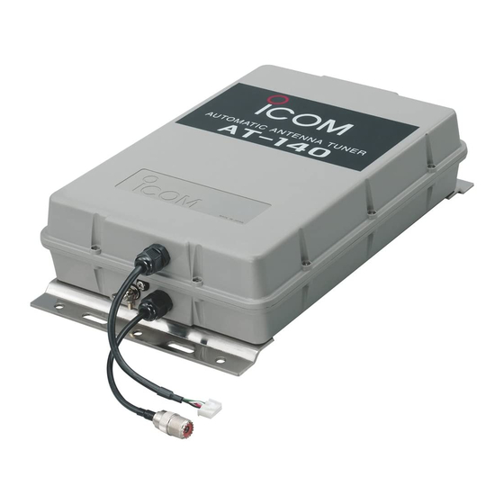
Page 11: Unit Description And Specifications
UNIT DESCRIPTION AND SPECIFICATIONS Unit description Ground terminal Water drain screw Antenna cable receptacle Antenna terminal Mounting plate Specifications • Frequency coverage • Power supply requirement • Current drain • Operating temperature range • Weight • Antenna connector • Max. Input power •... - Page 12 A-6175H-1EX Printed in Japan © 2002 Icom Inc. Icom America Inc. Icom (Europe) GmbH <Corporate Headquarters> Communication Equipment 2380 116th Avenue N.E., Bellevue, WA 98004, U.S.A. Himmelgeister Str. 100, Phone: (425) 454-8155 Fax: (425) 454-7619 D-40255 Düsseldorf, Germany URL: http//www.icomamerica.com Phone: 0211 346047 URL: http//www.icomeurope.com...
Need help?
Do you have a question about the AT-140 and is the answer not in the manual?
Questions and answers