Icom AT-130 Service Manual
Hf automatic antenna tuner
Hide thumbs
Also See for AT-130:
- Instruction manual (16 pages) ,
- Instruction manual (12 pages) ,
- Instruction manual (14 pages)
Table of Contents
Advertisement
Advertisement
Table of Contents

Related Manuals for Icom AT-130


Summary of Contents for Icom AT-130
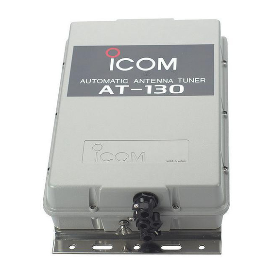
- Page 1 SERVICE MANUAL HF AUTOMATIC ANTENNA TUNER AT-130 AT-130E AT-140...
- Page 2 Addresses are provided on the inside back cover for your convenience. Icom, Icom Inc. and are registered trademarks of Icom Incorporated (Japan) in the United States, the United Kingdom, Germany, France, Spain, Russia and/or other countries.
- Page 3 TABLE OF CONTENTS SECTION 1 SPECIFICATIONS SECTION 2 INSIDE VIEW SECTION 3 CIRCUIT DESCRIPTION SECTION 4 ADJUSTMENT PROCEDURES SECTION 5 PARTS LIST SECTION 6 MECHANICAL PARTS SECTION 7 SEMI-CONDUCTOR INFORMATION SECTION 8 BOARD LAYOUTS 8 - 1 TUNER UNIT ..............8 - 1 8 - 2 MANUAL UNIT (AT-130E ONLY) .
- Page 4 (projections not included) ⁄ ⁄ ⁄ (D) in • Case construction : Weatherproof • Weight (AT-130/AT-140) Approx. 2.5 kg; 5 lb 8 oz (AT-130E) Approx. 2.7 kg; 6 lb • Control cable : OPC-420 (For [IC-77/78]) OPC-566 (For [IC-M700PRO], [IC-M710/RT])
- Page 5 SECTION 2 INSIDE VIEW Antenna terminal Antenna terminal LED's LED's (DS1-DS23: EL204HD) (DS1-DS23: EL204HD) Dip switch Dip switch Mode switch Mode switch (SW5: SSGM18049A) (SW5: SSGM18049A) (SW1: MS621C) (SW1: MS621C) Dip switch Dip switch (SW4: SSGM17012A) (SW4: SSGM17012A) Dip switch Dip switch Control cable Control cable...
- Page 6 CIRCUIT DESCRIPTION 3-1 GENERAL (1) FORWARD POWER DETECTOR (2) SWR DETECTOR An 8-bit microprocessor controls the AT-130/AT-130E/AT- (3) PHASE DETECTOR 140. The tuner matches the antenna system to the trans- (4) IMPEDANCE DETECTOR ceiver by using four kinds of detector circuits. These circuits are: Detailed descriptions of each circuit as follows.
- Page 7 3-4 PHASE DETECTOR CIRCUIT 3-6 LOGIC CIRCUIT This circuit consists of L2, L3 and IC9. The phase detector’s IC1, The CPU, controls the antenna matching network. The purpose is to detect reactance components and provide a CPU receives +5V through IC8 when DC power is applied to pure resistance.
- Page 8 Current capacity : Depended on connecting transceiver (Ex; 30 A or more) Frequency range : DC–20 MHz Oscilloscope Measuring range : 0.01–10 V Transceiver : Icom transceiver • CONNECTION AT-130/E AT-140 DC power supply Icom Transceiver Antenna connector Tuner receptacle (Refer to below)
- Page 9 4-2 ANTENNA TUNER ADJUSTMENTS ADJUSTMENT MEASUREMENT POINT ADJUSTMENT ADJUSTMENT CONDITION VALUE UNIT LOCATION UNIT ADJUST PHASE • S1 : PRESET TUNER Connect an oscillo- 5 V (Tune R194 just TUNER • S4-7 : OFF scope to the check before droped.) DETECTOR CIRCUIT •...
- Page 10 SECTION 5 PARTS LIST [TUNER UNIT] [TUNER UNIT] ORDER ORDER DESCRIPTION DESCRIPTION 1140003000 µPD78212CW-613 1710000060 DIODE 1SS55-T4 1130006930 TC74HC574AP 1710000060 DIODE 1SS55-T4 1130006930 TC74HC574AP 1710000060 DIODE 1SS55-T4 1710000060 DIODE 1SS55-T4 1130006930 TC74HC574AP 1710000060 DIODE 1SS55-T4 1130005200 TC74HC393AP 1710000060 DIODE 1SS55-T4 1130000050 TC4013BP 1710000060...
- Page 11 [TUNER UNIT] [TUNER UNIT] ORDER ORDER DESCRIPTION DESCRIPTION 7010003950 RESISTOR R20J 10 R106 7010004150 RESISTOR R20J 470 7010004320 RESISTOR R20J 10 k R107 7010004150 RESISTOR R20J 470 7070000730 RESISTOR CRH200 R-02J 330 R108 7010004150 RESISTOR R20J 470 7070000731 RESISTOR ERG2SJ 331 (330 R109 7010003990 RESISTOR...
- Page 12 RELAY AR-39251 4530000250 ARRAY B8XC0112-33N 4010000520 CERAMIC DD107-601 B 472K 50V 4010000520 CERAMIC DD107-601 B 472K 50V 6510000130 CONNECTOR FM MDR MI [AT-130/E] only 4530000250 ARRAY B8XC0112-33N 6910003140 CONNECTOR IMSA-9202B-1-02T 4010000520 CERAMIC DD107-601 B 472K 50V 6910003140 CONNECTOR IMSA-9202B-1-02T C100...
- Page 13 JUMPER IPS-1041-2 6910001020 JUMPER IPS-1041-2 W140 6910001020 JUMPER IPS-1041-2 9040401015 WIRE 74/98/045/X98/X98 W141 6910001020 JUMPER IPS-1041-2 9045201001 WIRE 74/98/040/X98/X98 [AT-130/E] only W142 6910001030 JUMPER IPS-1041-4 9045201001 WIRE 74/98/040/X98/X98 W144 6910001020 JUMPER IPS-1041-2 [AT-130/140] only W145 6910001030 JUMPER IPS-1041-4 6910001030 JUMPER...
- Page 14 TUBE IRRAX 1 (d) L=10 mm J313 6510006600 CONNECTOR RT01N-2.3A 9029403902 TUBE IRRAX 1 (d) L=5 mm J314 6510006600 CONNECTOR RT01N-2.3A 0910037981 B 3758A [AT-130/E] only J315 6510006600 CONNECTOR RT01N-2.3A J316 6510006600 CONNECTOR RT01N-2.3A J317 6510006600 CONNECTOR RT01N-2.3A J318 6510006600 CONNECTOR RT01N-2.3A...
- Page 15 REF. ORDER DESCRIPTION QTY. DESCRIPTION QTY. W501 8900011380 Cable OPC-1146 [AT-140] only 8930006910 Connector angle [AT-130/E] only W502 8900011400 Cable OPC-1164 [AT-140] only 8510000821 RF case (B)-1 8510000840 RF case (B) upper cover EP501 6910000880 Sheet NC-1 (SUS) [AT-130/E] only...
- Page 16 MP526 (C) MP525 (C) MP524 (C) MP523 (C) MP504 (C) MP505 (C) MP522 (C) MP541 (C) MP510 (C) MP508 (C) MP502 (C) MP539 (C) MP509 (C) MP536 (C) MP535 (C) MP537 (C) MP506 (C) MP510 (C) MP520 (C) MP521 (C) MP552 (C) TUNER UNIT MP519 (C)
- Page 17 SECTION 7 SEMI-CONDUCTOR INFORMATION • TRANSISTORS AND FET’S 2SA1048 GR 2SC2458 GR 2SC2688 O 2SK241 GR RN1204 • DIODES 1N60 1N4002 1S953 1S1555 1SS55 Green 1SS133 1SS265 MA700 RD8.2E B1 Grey Silver Yellow 7 - 1...
- Page 18 SECTION 8 BOARD LAYOUTS 8-1 TUNER UNIT to TRANSCIEVER (AT-130E only) to TRANSCIEVER ANTC (AT-130/E only) OUT1 to MANUAL unit J323 to MANUAL (AT-130E only) unit J301 CHASSIS W501 13.6 (AT-140 only) EP4 (USA-1, EUR-1 only) (AT-130E only) 1 20...
- Page 19 8-2 MANUAL UNIT (AT-130E ONLY) NOTE: Ref. No. is 300 series to antenna OUT2 J323 OUT1 J301 from TUNER unit P1 W21 (TUNER) W301 TUNER unit W302 8 - 2...
- Page 20 SECTION 9 BLOCK DIAGRAM Explanatory notes NETWORK VOLTAGE LINE (for AT-130E) COMMON LINE TRANSCEIVER (for AT-130/140) NETWORK D13, D14 1N60 1N60 NETWORK D7, D8, D11, D12 IC10 IC12 IC3, IC4 IC2, IC3 1N60 TA75393S PA2004C TC74HC574AP TC74HC574AP COMPARATOR BUFF LATCH...
- Page 21 SECTION 10 VOLTAGE DIAGRAM C162 RL14 22p(130/140) (for 130/E) RL25 RL26 L1 LR-22A 10p(130E) RL5-RL15 AR39251 AR39251 TUNER AJQ1341 AJQ1341 APQ3311x11 MANUAL RL10 RL11 RL12 RL13 RL15 W301 L2-L16 3Vp-p LA-473 180p LA-459 LA-460 LA-461 LA-462 LA-463 LA-464 LA-465 LA-466 LA-467 LA-468 LA-469...
- Page 22 Unit 9, Sea St., Herne Bay, Kent, CT6 8LD, U.K. Phone : +44 (01227) 741741 Fax : +44 (01227) 741742 : http://www.icomuk.co.uk Icom (Australia) Pty. Ltd. E-mail : info@icomuk.co.uk A.B.N. 88 006 092 575 290-294 Albert Street, Brunswick, Victoria, 3056, Australia Icom France S.a...
- Page 23 S-14014HZ-C1 1-1-32, Kamiminami, Hirano-ku, Osaka 547-0003, Japan C 2003 Icom Inc.
Need help?
Do you have a question about the AT-130 and is the answer not in the manual?
Questions and answers