Fluke 15B User Manual
Hide thumbs
Also See for 15B:
- Calibration manual (30 pages) ,
- User manual (28 pages) ,
- Calibration manual (23 pages)
Table of Contents

Related Manuals for Fluke 15B


Summary of Contents for Fluke 15B
- Page 1 15B & 17B Multimeters Users Manual PN 4228256 July 2012 © 2012 Fluke Corporation. All rights reserved. Printed in China. Specifications are subject to change without notice. All product names are trademarks of their respective companies.
- Page 2 LIMITED WARRANTY AND LIMITATION OF LIABILITY This Fluke product will be free from defects in material and workmanship for one year from the date of purchase. This war- ranty does not cover fuses, disposable batteries, or damage from accident, neglect, misuse, alteration, contamination, or abnormal conditions of operation or handling.
-
Page 3: Table Of Contents
Table of Contents Title Page Introduction ........................1 Safety Information ......................1 Safe Working Practices ....................1 Instrument Overview ...................... 5 Terminals ........................5 Display ........................5 Battery Saver ......................... 6 Making Measurements ....................6 Manual Ranging and Auto Ranging ................6 Data Hold ........................ - Page 4 15B & 17B Users Manual Measuring Frequency and Duty Cycle (17B only) ............. 10 Maintenance ........................10 General Maintenance ....................10 Testing the Fuses...................... 11 Replacing the Batteries and Fuses ................11 Service and Parts ......................11 General Specifications ....................12...
-
Page 5: Introduction
15B & 17B Multimeters Introduction Safety Information The Fluke Model 15B and 17B comply with IEC 61010- XWWarning 1:2001 Second Edition CAT II 1000 V, CAT III 600 V To avoid electric shock or personal injury, overvoltage standards. See Specifications. - Page 6 15B & 17B Users Manual • XWWarning Replace the batteries when the low battery indicator shows to prevent To prevent possible electrical shock, fire, or incorrect measurements. personal injury: • Comply with local and national safety • Read all safety Information before you codes.
- Page 7 Multimeters Safe Working Practices • Use only current probes, test leads, and adapters supplied with the Product. • Connect the common test lead before the live test lead and remove the live test lead before the common test lead. • Keep fingers behind the finger guards on the probes.
- Page 8 Ã Conforms to relevant South Korean EMC Standards Directive Annex I, this product is classed as category 9 "Monitoring and Control Instrumentation" product. Do not dispose of this product as unsorted municipal waste. Go to Fluke’s website for recycling information.
-
Page 9: Instrument Overview
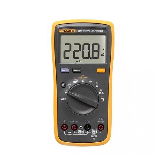
Multimeters Instrument Overview Instrument Overview Display Terminals mA A 400mA CAT I 1000 V FUSED CAT II 600 V FUSED apg2f.eps Item Description apg1f.eps Item Description Relative mode is active Continuity selected Input terminal for AC and DC current Display Hold is enabled measurements to 10A and frequency (17B Temperature is selected only) measurements. -
Page 10: Battery Saver
15B & 17B Users Manual Battery Saver Data Hold XWWarning The Meter enters the “Sleep mode” and blanks the display Dangerous voltages may be present at the if the Meter is not used and the input is inactive for 30 input terminals and may not be displayed. -
Page 11: Measuring Ac Or Dc Current
Multimeters Making Measurements the effects of ac transients while making accurate dc Measuring AC or DC Current measurements. XW Warning Choose ac or dc by turning the rotary switch to , , or . To prevent possible electrical shock, fire, or Connect the red test lead to the ... -
Page 12: Measuring Resistance
15B & 17B Users Manual Measure the resistance by touching the probes to the desired test points of the circuit. Read the measured resistance on the display. Testing for Continuity With the resistance mode selected, press the YELLOW button twice to activate the continuity beeper. If the resistance is under 50 Ω, the beeper will sound... -
Page 13: Testing Diodes
Multimeters Making Measurements Testing Diodes Measuring Capacitance XW Warning XW Warning To prevent possible electrical shock, fire, or To prevent possible electrical shock, fire, or personal injury, disconnect power and personal injury, disconnect power and discharge all high-voltage capacitors before discharge all high-voltage capacitors before you measure resistance, continuity, you measure resistance, continuity,... -
Page 14: Measuring Frequency And Duty Cycle (17B Only)
15B & 17B Users Manual XW Warning Measuring Frequency and Duty Cycle (17B only) The Meter can measure Frequency or Duty Cycle while To prevent possible electrical shock, fire, or making either an AC Voltage or AC Current measurement. personal injury: ... -
Page 15: Testing The Fuses
+85-276-6196 in Singapore leakage and damage to the Product if it is not +1-425-446-5500 anywhere in the world used for an extended period. Visit Fluke’s Web site at www.fluke.com To prevent possible electrical shock, fire, or personal injury:... -
Page 16: General Specifications
15B & 17B Users Manual General Specifications Maximum Voltage between any Terminal and Earth Ground: 1000 V Display: Digital: 4000 count updates 3/sec Operating: 0 °C to 40 °C, Storage: -30 °C to 60 °C indefinitely (to -40 °C for 100 hours) - Page 17 Multimeters General Specifications Overvoltage installation categories per The Meter is designed to protect against transients in these categories: IEC 61010-1, 2000: CAT II From equipment supplied from the fixed installation, e.g., TVs, PCs, portable tools and household appliances. CAT III From equipment in fixed equipment installations, e.g., installation panels, feeders and short branch circuits, and lighting systems in large buildings.
-
Page 18: Accuracy Specifications
Temperature specifications do not include thermocouple errors. After inserting the thermocouple plug into the meter, allow several minutes for thermal stabilization. The thermocouple supplied with this unit covers a temperature range of -40 °C to +260 °C. For probes that provide coverage outside this range, see the Fluke Accessories Brochure. - Page 19 Multimeters Accuracy Specifications Accuracy Function Range Resolution Model 15B Model 17B 400.0 Ω 0.1 Ω 0.5 % + 3 0.5 % + 3 4.000 kΩ 0.001 kΩ 0.5 % + 2 0.5 % + 2 Resistance (Ohms) 40.00 kΩ 0.01 kΩ...
- Page 20 15B & 17B Users Manual Accuracy Function Range Resolution Model 15B Model 17B 400.0 μA 0.1 μA AC Current (40 to 200 Hz) 1.5 % + 3 1.5 % + 3 4000 μA 1 μA 40.00 mA 0.01 mA AC Current (40 to 200 Hz) 1.5 % + 3...
- Page 21 Multimeters Accuracy Specifications Overload Input Impedance Common Mode Normal Mode Function Protection (Nominal) Rejection Ratio Rejection AC Volts 1000 V >10 MΩ <100 pF >60 dB at dc, 50 or 60 Hz DC Volts 1000 V >10 MΩ <100 pF >100 dB at dc, >45 dB at 50 or 60 Hz...
- Page 22 15B & 17B Users Manual...
Need help?
Do you have a question about the 15B and is the answer not in the manual?
Questions and answers