Table of Contents
Advertisement
Advertisement
Table of Contents

Subscribe to Our Youtube Channel
Related Manuals for Fluke 1587


Summary of Contents for Fluke 1587
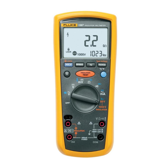
- Page 1 ® 1587/1577 Insulation Multimeters Calibration Manual PN 2456783 September 2005 Rev. 1, 6/09 © 2005, 2009 Fluke Corporation, All rights reserved. Printed in USA. Specifications are subject to change without notice. All product names are trademarks of their respective companies.
- Page 2 Fluke authorized resellers shall extend this warranty on new and unused products to end-user customers only but have no authority to extend a greater or different warranty on behalf of Fluke. Warranty support is available only if product is purchased through a Fluke authorized sales outlet or Buyer has paid the applicable international price.
-
Page 3: Table Of Contents
General Specifications ..................2 Electrical Specifications ..................3 AC Voltage Measurement ................3 1587 Accuracy ..................3 1587 Low-pass Filter Voltage ..............3 1577 Accuracy ..................3 DC Voltage Measurement ................4 DC Millivolts Measurement ................4 DC and AC Current Measurement ..............4 Ohms Measurement.................. - Page 4 Reassembling the Meter ................15 Required Tools and Equipment ................. 15 Performance Test ....................16 Testing the 1577 and 1587 DMM Functions..........16 Testing Temperature Function (1587 Only)..........18 Testing the Discharge Circuit ................ 18 Testing the Insulation Function ..............18 Insulation Resistance Accuracy Test............
- Page 5 Page Description of Symbols Used in the Manual............1 Required Tools and Equipment................15 DMM Accuracy Tests .................... 16 Insulation Resistance Accuracy Test..............19 Insulation Mode, Source Voltage Accuracy Tests ..........20 Calibration Adjustment Steps................. 26 1587/1577 Replacement Parts................28...
- Page 6 1587/1577 Calibration Manual...
- Page 7 LCD Display Test ....................9 Disassembling the Meter..................10 Insulation Terminal Clips..................13 Accessing the LCD ....................14 Source Voltage Accuracy Test................20 I Nominal Test......................21 Low-Battery Test Connections................22 Restoring the Default Password ................24 1587/1577 Replacement Parts................27...
- Page 8 1587/1577 Calibration Manual...
-
Page 9: Introduction
Earth Ground DC (Direct Current) Fuse WARNING: risk of electric shock. Double Insulated Battery (Low battery when shown on Important information; see manual display.) Do not dispose of this product as unsorted municipal waste. Go to Fluke’s website for recycling information. -
Page 10: Contacting Fluke
1587/1577 Calibration Contacting Fluke To contact Fluke, call one of the following telephone numbers: • Technical Support USA: 1-800-44-FLUKE (1-800-443-5853) • Calibration/Repair USA: 1-888-99-FLUKE (1-888-993-5853) • Canada: 1-800-36-FLUKE (1-800-363-5853) • Europe: +31 402-675-200 • Japan: +81-3-3434-0181 • Singapore: +65-738-5655 •... -
Page 11: Electrical Specifications
600.0 V 0.1 V ±(2 % + 3) ±(2 % + 3) 1000 V 1 kHz bandwidth. 1587 Low-pass Filter Voltage 50 Hz to 60 Hz 60 Hz to 400 Hz Range Resolution ±(% of Rdg + Digits) ±(% of Rdg + Digits) +(2 % + 3) ±(1 % + 3) -
Page 12: Dc Voltage Measurement
Overload Protection ..........1000 V rms or dc Open Circuit Test Voltage........<8.0 V dc Short Circuit Current ........... <1.1 mA Diode Test (1587 Only) Diode Test Indication .......... Display voltage drop: 0.6 V at 1.0 mA nominal test current: Accuracy ............. ±(2 % + 3) -
Page 13: Continuity Test
Accuracies apply following 90 minutes settling time after a change in the ambient temperature of the instrument. Insulation Specifications Measurement Range .......... 0.1 MΩ to 2 GΩ model 1587, 0.1 MΩ to 600 MΩ model 1577 Test Voltages ............50, 100, 250, 500, 1000 V model 1587, 500 and 1000 V model 1577 Test Voltage Accuracy........ -
Page 14: Model 1587
1587/1577 Calibration Model 1587 Resistance Accuracy Output Voltage Display Range Resolution Test Current ±(% of Rdg + Digits) 0.01 to 6.00 MΩ 0.01 MΩ 50 V ±(3 % + 5 counts) 1 mA @ 50 kΩ (0 % to + 20 %) 6.0 to 50.0 MΩ... - Page 15 A Message From Fluke Corporation Some semiconductors and custom IC's can be damaged by electrostatic discharge during handling. This notice explains how you can minimize the chances of destroying such devices 1. Knowing that there is a problem.
- Page 16 8. WHEN REMOVING PLUG-IN ASSEMBLIES 5. USE STATIC SHIELDING CONTAINERS FOR HANDLE ONLY BY NON-CONDUCTIVE HANDLING AND TRANSPORT. EDGES AND NEVER TOUCH OPEN EDGE CONNECTOR EXCEPT AT STATIC-FREE WORK STATION. PLACING SHORTING STRIPS ON EDGE CONNECTOR HELPS PROTECT INSTALLED S.S. DEVICES. 6.
-
Page 17: Testing The Fuse
Insulation Multimeters Basic Maintenance Testing the Fuse XWWarning To avoid electrical shock or injury, remove the test leads and any input signals from the Meter before replacing the fuse. Test the fuse as described below and illustrated in Figure 1. If the fuse is defective, see Replacing the Batteries and/or Fuse later in this manual. -
Page 18: Replacing The Batteries And/Or Fuse
Min interrupt rating 10 000 A ebp02f.eps Fuse, Fast, 440 mA, 1000 V, Min Interrupt Rating 10000 A Fluke PN 943121 Battery, 1.5 V AA Alkaline, NEDA 15A, IEC LR6 Fluke PN 376756 Figure 2. Replacing the Batteries and Fuse... -
Page 19: Testing The Display
Insulation Multimeters Basic Maintenance Testing the Display The display is an LCD comprised of a series of characters and segments for providing the user with a variety of information. To test the LCD and all of its segments proceed as follows: 1. -
Page 20: Disassembling And Reassembling The Meter
1587/1577 Calibration Disassembling and Reassembling the Meter This section of the manual provides instructions for disassembling and reassembling the Meter. The instructions are limited to major replaceable assemblies and do not include component-level detail. See Figure 4 for an exploded view of the major assemblies. -
Page 21: Removing The Boot
Insulation Multimeters Disassembling and Reassembling the Meter Removing the Boot The standard Meter comes equipped with a snug-fitting yellow rubber boot. The boot helps protect the Meter from rough handling and is normally left on the Meter. The first step in disassembling the Meter is to remove the boot. Use the following procedure to remove the boot: 1. -
Page 22: Removing The Bottom Case
1587/1577 Calibration Removing the Bottom Case With the battery door removed, the next step in disassembling the Meter is to remove the bottom case. Use the following procedure to remove the bottom case: Note When removing the back case, it is not necessary to remove the fuse or the batteries. -
Page 23: Removing The Lcd
Insulation Multimeters Disassembling and Reassembling the Meter ebp11f.eps Figure 5. Insulation Terminal Clips Removing the LCD With the PCA removed, the final step in disassembling the Meter is to remove the LCD assembly from the PCA. Refer to Figure 6 and use the following procedure to remove the LCD assembly: 1. - Page 24 1587/1577 Calibration 3. Remove the old glass LCD display from the bezel. Note Make sure the new LCD display is clean (free of lint and finger prints) before placing it in position in the bezel. 4. Position the new glass LCD display in the bezel; the silver face should face the rear, and the stepped portion of the glass should be directly under the elastomeric slot on the bezel.
-
Page 25: Reassembling The Meter
Table 2. Required Tools and Equipment Equipment Required Characteristics Recommended Model Calibrator AC Voltage Range: 0-1000V Fluke 9100 w/135 option Accuracy: +/- 0.25% Frequency Range: 50Hz - 5 kHz Accuracy: +/-3% DC Voltage: 0-1000V Accuracy: +/-0.075% Current Range: 0-600 mA Accuracy: AC mA = +/-0.38%... -
Page 26: Performance Test
If the Meter does not pass all parts of the performance tests, repair and/or calibration adjustment are required. A calibration adjustment procedure is given later in this manual. If significant repairs are required, contact Fluke as described toward the front of this manual. If user repairs are appropriate, refer to the... - Page 27 Insulation Multimeters Performance Test Table 3. DMM Accuracy Tests (cont) UUT Display Reading Step Function Range Input Level Fluke 1577 Fluke 1587 V dc 600.0V -600.0V -601.4 to -598.6 -600.3 to -599.7 V dc 1000V 1000V 996 to 1004 997 to 1003 mV dc 600.0 mV...
-
Page 28: Testing Temperature Function (1587 Only)
1587/1577 Calibration Testing Temperature Function (1587 Only) Use the following procedure to verify that the UUT measures temperature within the published specification. 1. Connect the K-Type thermocouple to the temperature input of the UUT (J) and temperature calibrator. Note To ensure an accurate measurement the UUT and thermocouple connector must be at the same temperature. -
Page 29: Insulation Function, External Sense
500 V 500 MΩ 600 MΩ >550 >550 1000 V 2.0 GΩ 1.7 GΩ 1000 V 600 MΩ 600 MΩ 1587 Only 1000 V 60.0 MΩ 1 MΩ 50 V 6.00 MΩ 100 kΩ 0.05 0.15 50 V 50.0 MΩ... -
Page 30: Insulation Function, Source Voltage Accuracy Test
Test DMM Display Reading UUT Display Reading Insulation 500 V 500.0 to 600.0 500 to 600 Insulation 1000V 1000.0 to 1200.0 1000 to 1200 1587 Only Insulation 50.0 to 60.0 50 to 60 Insulation 100V 100.0 to 120.0 100 to 120 Insulation 250V 250.0 to 300.0... -
Page 31: I Nominal Test
Insulation Multimeters Performance Test I Nominal Test The following test verifies the ability of the UUT to maintain the nominal insulation test current while loaded. 1. Connect the Test DMM and Calibrator to the UUT INSULATION terminals as shown in Figure 8. 2. -
Page 32: Low-Battery Test - Insulation Function
1587/1577 Calibration UUT (Rear) UUT (Front) 6.0 Vdc Power Supply Power Supply ebp08f.eps Figure 9. Low-Battery Test Connections Low-Battery Test - INSULATION Function The following procedure verifies the accuracy of the low-battery indicator (b) during insulation operation. XWWarning To avoid shock hazard DO NOT press t during the following procedure. -
Page 33: Calibration Adjustment Procedure
Insulation Multimeters Calibration Adjustment Procedure Calibration Adjustment Procedure The following sections comprise the Calibration Adjustment Procedure. The procedure is meant to bring the UUT back into specification following repair of the UUT or when the UUT fails the Performance Test. The required equipment is listed earlier in Table 2. - Page 34 1587/1577 Calibration 2. Remove the back case from the UUT. Leave the PCA in the top case. 3. Apply 6.0 V across the battery pads (XBT1) + and – on the back of the PCA. See Figure 10. XWWarning To avoid electrical shock or personal injury, remove the test leads and any input signal before removing the back case from the UUT.
-
Page 35: Meter Keys Used In The Calibration Steps
Insulation Multimeters Calibration Adjustment Procedure Meter Keys Used in the Calibration Steps The Meter keys behave as follows when performing the Calibration Adjustment Procedure. This may be of help determining why a calibration step is not accepted and for determining the input value without referring to Table 6. Press and hold to show the measured value. - Page 36 Calibration Adjustment Step Input Value Terminal (Function) C-01 AC Volts V/COM 600.0 mV, 60 Hz C-02 (Model 1587 only) 600.0 mV, 5 kHz C-03 6.000 V, 60 Hz C-04 (Model 1587 only) 6.000 V, 5 kHz C-05 60.00 V, 60 Hz C-06 (Model 1587 only) 60.0 V, 5 kHz...
-
Page 37: Service And Parts
User service is limited to replacing parts. Table 7 identifies the parts available for replacement and Figure 11 shows the location of each part. To order replacement parts refer to Contacting Fluke earlier in this manual. ebp09f.eps Figure 11. 1587/1577 Replacement Parts... - Page 38 1587/1577 Calibration Table 7. 1587/1577 Replacement Parts Item Ref Des Description 2277944 1577, Case Top 2277926 1587, Case Top 2277971 1577, Bracket, Mask 2277967 1587, Bracket, Mask 2281339 1577, Keypad 2281342 1587, Keypad 2277892 15x7, Shield, Bottom 2386438 1577, Door, Battery...
Need help?
Do you have a question about the 1587 and is the answer not in the manual?
Questions and answers