Table of Contents
Advertisement
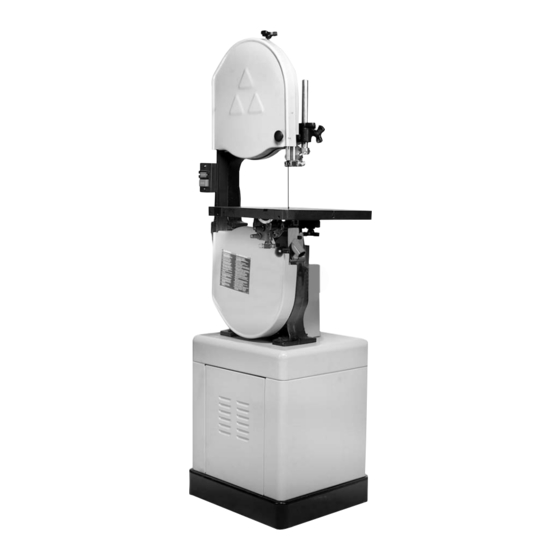
14"
Wood Cutting
Band Saw
(Model 28-280)
The Serial No./Model No. plate is attached to the
right side of the base casting. Locate this plate and
record the Serial No. and Model No. in your manual
for future reference.
SERIAL NO.___________________________________
MODEL NO. __________________________________
DATED 1-15-96
PART NO. 426-02-651-0023
©Delta International Machinery Corp. 1996
Advertisement
Table of Contents

Related Manuals for Delta 28-280


Summary of Contents for Delta 28-280
-
Page 1: Wood Cutting
The Serial No./Model No. plate is attached to the right side of the base casting. Locate this plate and record the Serial No. and Model No. in your manual for future reference. SERIAL NO.___________________________________ MODEL NO. __________________________________ DATED 1-15-96 PART NO. 426-02-651-0023 ©Delta International Machinery Corp. 1996... -
Page 2: Additional Safety Rules For Band Saws
Figure out an alternative procedure that feels safer. REMEMBER: Your personal safety is your responsibility. This machine was designed for certain applications only. Delta Machinery strongly recommends that this machine not be modified and/or used for any application other than that for which it was designed. If you have any questions relative to a particular application, DO NOT use the machine until you have first contacted Delta to determine if it can or should be performed on the product. -
Page 3: Unpacking And Cleaning
UNPACKING AND CLEANING Carefully unpack the band saw and all loose items from the shipping container. Remove the protective coating from the machined surfaces of the band saw. This coating may be removed with a soft cloth moistened with kerosene (do not use acetone, gasoline or lacquer thinner for this purpose). -
Page 5: Assembling Belt And Pulley Guard
ASSEMBLING BELT AND PULLEY GUARD Assemble the belt and pulley guard (A) to the top of the stand, as shown in Fig. 6, using the two 1/4-20 x 1/2 hex head screws, washers and nuts (B). ASSEMBLING SWITCH If you purchased your band saw complete with stand and elec- Fig. -
Page 6: Starting And Stopping Saw
5. Fasten the switch box to the band saw arm using two nuts and lockwashers (A) Fig. 10, which were removed in STEP 3. Fig. 10 6. Remove screw and cable clamp (E) Fig. 11, from lower arm of band saw. 7. -
Page 7: Tilting The Table
TABLE INSERT Place table insert (A) Fig. 14, in the hole provided in the table, making sure the pin (B) in the table engages one of the indents in the table insert. Fig. 14 TILTING THE TABLE The table on your band saw can be tilted 45 degrees to the right and 10 degrees to the left. -
Page 8: Adjusting Blade Tension
ADJUSTING BLADE TENSION On the back of the upper wheel slide bracket, there is a series of graduations. These indicate the proper tension for various widths of blades. With the blade on the wheels, turn the knob (A) Fig. 18, to raise or lower the wheel, until the red fiber washer (B) is in line with the proper graduation for the size of blade being used. -
Page 9: Adjusting Upper Blade Guide Assembly
ADJUSTING UPPER BLADE GUIDE ASSEMBLY The upper blade guide assembly (A) Fig. 21, should always be set as close as possible to the top surface of the material being cut by loosening lock knob (B) and moving the guide assembly (A) to the desired position. -
Page 10: Adjusting Upper Blade Guides And Blade Support Bearing
ADJUSTING UPPER BLADE GUIDES AND BLADE SUPPORT BEARING The upper blade guides and blade support bearings are ad- justed only after the blade is tensioned and tracking properly. To adjust proceed as follows: 1. The upper blade guides (A) Fig. 23, are held in place by means of the set screws (B).
Need help?
Do you have a question about the 28-280 and is the answer not in the manual?
Questions and answers