Table of Contents
Advertisement
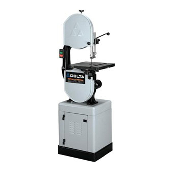
14" Band Saws
(Models 28-206, 28-276)
MODEL 28-206
SHOWN
PART NO. 906452 - 08-16-02
Copyright © 2002 Delta Machinery
To learn more about DELTA MACHINERY
ESPAÑOL: PÁGINA 25
visit our website at: www.deltamachinery.com.
For Parts, Service, Warranty or other Assistance,
1-800-223-7278 (
1-800-463-3582).
please call
In Canada call
Advertisement
Table of Contents

Related Manuals for Delta 28-206


Summary of Contents for Delta 28-206
- Page 1 (Models 28-206, 28-276) MODEL 28-206 SHOWN PART NO. 906452 - 08-16-02 Copyright © 2002 Delta Machinery To learn more about DELTA MACHINERY ESPAÑOL: PÁGINA 25 visit our website at: www.deltamachinery.com. For Parts, Service, Warranty or other Assistance, 1-800-223-7278 ( 1-800-463-3582).
-
Page 2: General Safety Rules
If you have any questions relative to a particular application, DO NOT use the machine until you have first contacted Delta to determine if it can or should be performed on the product. -
Page 3: Save These Instructions
ADDITIONAL SAFETY RULES FOR BAND SAWS WARNING: FAILURE TO FOLLOW THESE RULES MAY RESULT IN SERIOUS PERSONAL INJURY. DO NOT OPERATE THIS MACHINE UNTIL it is 15. TURN THE MACHINE “OFF” to back out of an assembled and installed according to the uncompleted or jammed cut. -
Page 4: Power Connections
POWER CONNECTIONS A separate electrical circuit should be used for your machines. This circuit should not be less than #12 wire and should be protected with a 20 Amp time lag fuse. If an extension cord is used, use only 3-wire extension cords which have 3- prong grounding type plugs and matching receptacle which will accept the machine’s plug. -
Page 5: Extension Cords
FOREWORD The Delta Model 28-206 is a 1 Hp, 120/240 V, 2 speed unit with a quick blade tensioning device and an enclosed stand. The Delta Model 28-276 is a ¾ Hp, 120/240 V, 1 speed unit with a quick blade tensioning device and an open stand. - Page 6 BAND SAW PARTS Fig. 2 1. Band Saw 8. M8 Lockwasher (4) (for assembling saw to stand) 2. Motor 9. M8 Flat Washer (4) (for assembling saw to stand) 3. Table 10. M8x1.25 Hex nut (4) (for assembling saw to stand) 4.
- Page 7 MODEL 28-206 ENCLOSED STAND PARTS Fig. 3 9. M5x0.8x10mm Pan Head Screw (2) 1. Base (2) 10. Shaft (for attaching motor plate to top of stand) 2. Side (2) 11. M8x1.25 Hex nut 3. Stand Top 12. Dampening Cap 4. Door (2) 13.
- Page 8 MODEL 28-276 OPEN STAND PARTS Fig. 4 9. Dampening Cap 1. Legs (4) 10. M8x1.25x16mm Round Head Flange Screw (4) 2. Stand Top 11. M8x1.25x16mm Carriage Head Screw (32) 3. Long Brace (2) 12. M8x1.25 Hex Flange Nut (38) 4. Short Brace (2) 13.
- Page 9 MODEL 28-206 ENCLOSED STAND ASSEMBLY WARNING: FOR YOUR OWN SAFETY, DO NOT CONNECT THE MACHINE TO THE POWER SOURCE UNTIL THE MACHINE IS COMPLETELY ASSEMBLED AND YOU READ AND UNDERSTAND THE ENTIRE INSTRUCTION MANUAL. 1. Place the stand top (A) Fig. 5, on a flat surface as shown.
- Page 10 14. Align the holes in the base (A) Fig. 8, with the holes in the two sides (B). 15. Insert a M8x1.25x16mm hex head flange screw through the hole in the side of the stand (B) Fig. 8, and through the hole in the base (A). 16.
- Page 11 MODEL 28-276 OPEN STAND ASSEMBLY WARNING: FOR YOUR OWN SAFETY, DO NOT CONNECT THE MACHINE TO THE POWER SOURCE UNTIL THE MACHINE IS COMPLETELY ASSEMBLED AND YOU READ AND UNDERSTAND THE ENTIRE INSTRUCTION MANUAL. 1. Place the stand top (A) Fig. 10, on a flat surface as shown.
- Page 12 14. Align the four holes in the short brace (A) Fig. 14, with the four holes in the two legs (B). 15. Insert a M8x1.25x16mm carriage head bolt through the hole in the stand and the hole the short brace. 16.
-
Page 13: Attaching Saw To Stand
1. Place the belt over the saw pulley (A) Fig. 18. NOTE: THE MODEL 28-276 HAS ONLY A ONE STEP PULLEY. THE MODEL 28-206 HAS A TWO STEP PULLEY AS SHOWN IN FIG. 18. 2. Lift the motor and place the other end of the belt around the motor pulley (B) Fig. - Page 14 ATTACHING THE TABLE TO THE SAW 1. Remove the band saw blade. 2. Align the two table studs (A) Fig. 19, in the bottom of the table, with the two holes in the trunnion assemblies (B). NOTE: MAKE SURE THE SLOT (C) FIG. 19, IN THE TABLE IS FACING TOWARD THE FRONT OF THE SAW.
-
Page 15: Tilting The Table
OPERATING CONTROLS AND ADJUSTMENTS STARTING AND STOPPING SAW The power switch is located on the left side of the machine. To turn the machine “ON”, push the green start button (A) Fig. 23. To turn the machine “OFF”, push the red stop button (B). Fig. -
Page 16: Adjusting Blade Tension
ADJUSTING THE TABLE STOP The tool is equipped with an adjustable table stop (A) Fig. 26 that allows the table to be set at 90 degrees to the blade. Tilt the table (C) Fig. 26 to the left until the table stop (A) Fig. -
Page 17: Tracking The Blade
TRACKING THE BLADE CAUTION: DISCONNECT MACHINE FROM POWER SOURCE. IMPORTANT: Before tracking the blade, make sure that the blade guides and blade support bearings are clear of the blade. After applying tension to the blade, rotate the wheels slowly forward by hand and observe the blade’s movement. -
Page 18: Dust Port
5. Two set screws (B) Fig. 35 hold the upper blade guides (A) in place. Loosen the set screws (B) to move the guides (A). Place them as close as possible to the side of the blade. (Be careful not to pinch the blade). Tighten the screws (B). -
Page 19: Cutting Curves
CHANGING BLADE SPEED FOR MODEL 28-206 ONLY 1. DISCONNECT MACHINE FROM POWER SOURCE. 2. Open the pulley guard (A) Fig. 37, by removing screw (B) and opening the pulley guard door. 3. Lift and hold the motor up, place the belt on desired step of the pulleys, and release the motor. -
Page 20: Troubleshooting Guide
TROUBLESHOOTING GUIDE In spite of how well a band saw is maintained, problems can occur. The following troubleshooting guide will help you solve the more common problems: Trouble: SAW WILL NOT START. Probable Cause Remedy 1. Saw not plugged in. 1. - Page 21 Trouble: BLADE WILL NOT TRACK. Probable Cause Remedy 1. Blade too loose 1. Adjust tension 2. Upper wheel not properly adjusted. 2. Adjust upper wheel. 3. Improperly adjusted blade support bearing. 3. Adjust blade support bearing. Trouble: CUT DOES NOT AGREE WITH SETTING ON THE TILT SCALE. Probable Cause Remedy 1.
-
Page 22: Band Saw Blades
This will save blades and will produce better cuts. For cutting wood and similar materials, Delta offers blades in widths of 1/8", 1/4", 3/8", and 1/2". Any one of a number of conditions may cause a band saw blade to break. Blade breakage is, in some cases, unavoidable, being the natural result of the peculiar stresses to which blades are subjected. - Page 23 NOTES...
- Page 24 Two Year Limited Warranty Delta will repair or replace, at its expense and at its option, any Delta machine, machine part, or machine accessory which in normal use has proven to be defective in workmanship or material, provided that the customer returns the product prepaid to a Delta factory service center or authorized service station with proof of purchase of the product within two years and provides Delta with reasonable opportunity to verify the alleged defect by inspection.
Need help?
Do you have a question about the 28-206 and is the answer not in the manual?
Questions and answers