
Related Manuals for Cub Cadet 23HP Z-Force 48


Summary of Contents for Cub Cadet 23HP Z-Force 48
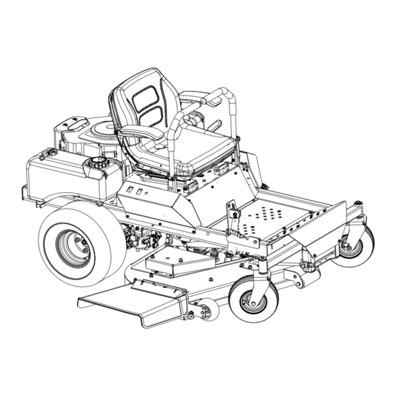
- Page 1 Hydrostatic Zero-Turn Residential Riding Mower Turf Equipment MODEL 23HP Z-Force 48 w/ Fabricated Deck OPERATOR’S AND SERVICE MANUAL...
-
Page 2: Table Of Contents
TABLE OF CONTENTS Foreword............. . . 3 General Safety Operations . -
Page 3: Foreword
FORWARD The Hydrostatic Zero-Turn Riding Mower provides superb maneuverability and mid-mount cut- ting. The machine incorporates many safety features that should be studied by all operators before use. The list of safety precautions should receive particular attention. This manual presents all of the operating and maintenance instructions necessary to keep your mower at peak efficiency. -
Page 4: General Safety Operations
WARNING • The engine exhaust, some of its constituents, and certain vehicle components contain or emit chemicals known to the State of California to cause cancer, birth defects or other reproductive harm. • This unit is equipped with an internal combustion engine and should not be used on or near any unimproved forest-covered, brush-covered, or grass-covered land unless the engine’s exhaust system is equipped with a spark arrester meeting applicable local or state laws (if any). -
Page 5: Slope Operation
• Do not mow on wet grass. Reduced traction 22. Use only accessories approved for this could cause sliding. machine by Cub Cadet. Read, understand • Do not try to stabilize the machine by putting and follow all instructions provided with the your foot on the ground. -
Page 6: Service
Use extra care when approaching blind cor- Grass catcher components are subject to ners, shrubs, trees or other objects that may wear, damage and deterioration, which could obscure your vision of a child or other hazard. expose moving parts or allow objects to be Remove the key when the machine is left thrown. -
Page 7: Related To Fuel
cases should not be punctured. Lead is poisonous G. Towing and is contained within the positive and negative ter- 1. Tow only with a machine that has an minals as well as within the battery’s internal grid- approved hitch designed for towing. Do not work of plates and active materials. -
Page 8: Safety Decals
SAFETY DECALS AND LABELS Belt Routing Part Number: 777I22444 Part Number: 02005245 TO R EDU CE THE RISK O F IN JU RY , D O N O T O P E R A T E M O W E R U N L E S S D ISC H A R G E C H U TE C O VER OR GR A S S C A T C H E R IS I N I T S P R O P E R P L A C E . -
Page 9: Specifications
SPECIFICATIONS Engine: 23HP Kohler Courage Pro Type: Vertical air cooled V-Twin Air Cleaner: Paper element Lube System: Pressurized with oil filter, drain valve with hose Starter: 12-volt electric Traction Drive: Engine to variable-speed integrated hydraulic pump and wheel motors on each drive wheel Cutter Deck;Drive: 48”... -
Page 10: Operating Instructions
OPERATING INSTRUCTIONS Figure. 1 Figure. 2 parking brake Hour Meter Electric Blade Ignition Switch Choke Engine throttle Clutch Switch A. General k. Be careful when crossing gravel paths or roadways. Always turn off the blade clutch 1. When Mowing: switch and wait until the blades stop rotat- a. -
Page 11: Controls
2. Safety Awareness when Mowing next and each subsequent time that the a. Do not operate on steep slopes, those area is mowed. above 15 degrees (27% slope). B. Controls b. Avoid turning downhill if possible, use extra 1. Engine Ignition and Start Switch: (See Fig- care and go slowly. - Page 12 Steering Levers Figure. 4 Fuel Shutoff Valve Seat Adjustment Lever: The Seat Adjust- ment Lever is located beneath the seat. The Figure. 3 Seat Adjustment Lever is used to move the Deck Lift Pedal seat forward and backward. To place the seat 4.
-
Page 13: Initial Adjustments
C. Initial Adjustments plugs and using the foot pedal, lower the mowing deck into the cutting position. 1. Check the fluid levels and tires: b. Using a ruler, pencil and paper, measure Note: and note the distance from the paved sur- These checks should be made daily, face to the bottom edge of the mowing before starting the engine. -
Page 14: Zero Turn Break-In And Operating Procedures
5. Lubricate all fittings listed in the mainte- 1. Make sure the park brake is set to the nance section. “ON” position, both lap bars are in the neutral/start position, and the Power D. Zero Turn Break-In And Operating Take Off (PTO also referred to as blade Procedures control switch) is in the “off”... - Page 15 toward the opposite from the side that 1. Please note, a zero turn maneuver can was advanced — I.E. to turn clockwise not be executed while the machine is (to the Right), move the LEFT lap bar for- moving in the forward or, reverse direc- ward more than the right side, and to tions, the machine must come to a stop turn counter-clockwise (to the LEFT),...
-
Page 16: Maintenance And Service
e. Push the throttle control to the full forward to be careful to avoid turning too fast and position. too far. Insert the key in the ignition and start switch After you have mastered operating the and turn the switch to “On”. mower, use the deck lift pedal to lower the g. -
Page 17: Mower Deck
Trailing Link hair pin hair pins Figure. 6 Thread hose coupler (packaged with this B.Mower Deck manual) onto the end of your garden hose. Removing the Mower Deck: See Figure 7. a. Apply the parking brake. Remove ignition Attach the hose coupler to the water port key and both spark plug caps. -
Page 18: Hydrostatic Drive System
g. To replace the blade reverse the above process and tighten nut to 100-120 lb ft. Note: Add a small amount of multi-purpose grease to the bolt threads to avoid corrosion and galvenic action. WARNING: Never mow with dull blades! Blades that are Spindle bent should be replaced! The cutting blades are sharp and can cause severe injury. -
Page 19: Electrical Circuit
D.Electrical Circuit 4. Installing the Battery Note: The battery is delivered from the fac- Danger: tory fully charged and filled with electrolyte. a. Attach the positive (red) cable. Read General Safety Precautions Nos. 9 and 10. b. Attach the negative (black) cable. 1. -
Page 20: Tires
should rotate. If the blades do not turn, the mount from the operator’s seat, the seat blade clutch switch must be replaced, the switch must be replaced. seat switch must be replaced or the elec- d. Electric PTO Clutch: This clutch operates tric PTO clutch must be repaired. -
Page 21: Brakes
the wheel. Mount a wheel and tire, replace the rear and lower the wide area of the rod into the keyhole slot. (See photo below ) lug nuts, and using a torque wrench, tighten them to 60 10 ft-lbs. ± If the leaking tire is on a front caster wheel, block both traction wheels and raise the caster wheel so that the tire is an inch off the ground. -
Page 22: Storage
neutral position. If the mower begins to creep, d. Lower the mower off the block and check contact your service representative. the tire pressure. e. Push the mower outdoors and start the H. Storage engine. Let the engine idle until it has warmed up completely (4 to 5 minutes). -
Page 23: Maintenance Schedule
MAINTENANCE SCHEDULE 6. Lubricate all grease fittings. Follow the Lubrication Chart. A. Daily Checks D. Every 100 Hour Checks 1. Before starting engine: 1. Change the engine oil filter. (Every 50 hours a. Check the fuel level by viewing in the tank. under heavy duty operation.) b. -
Page 24: Lubrication Chart
OIL CHART Apply a few drops of SAE engine oil, grease, or use a spray lubricant. Apply the oil to both sides of pivot points. Wipe off any excess. Start engine and operate mower briefly to insure that oil spreads evenly. Number of Oil Points Description DAILY... -
Page 25: Performance Adjustments
Performance Adjustments B. Engine RPM Check and Adjustment Table 1 Description High RPM Spec. Low RPM Spec. A. High Speed Tracking Adjustment 23 Kohler 3475 +/-75 1550 +/-100 If mower tracks to one side with both lap bars in fully NOTE: RPM Specs. -
Page 26: Deck Corner Ball Wheel Roller Settings
g. Verify proper throttle adjustment by check- b. Remove the bolts and lap bar and reposi- ing RPM readings as outlined above. tion to the second set of holes in the mount- ing block. C. Deck Corner Ball Wheel Roller Settings c. -
Page 27: Deck Leveling Procedure
F.Deck leveling Procedure right blade tip adjustment is fixed and you level to that height, adjusting the decks will be simpli- Park the mower on a flat paved surface, engage fied. the parking brake, shut off the engine, remove Front the key from the ignition switch, disconnect the Outer Jam Nuts of Unit... -
Page 28: Wiring Diagram
WIRING DIAGRAM GD: 02002990... -
Page 29: Slope Gauge
SLOPE GAUGE... -
Page 30: Maintenance Record
MAINTENANCE RECORD DATE WORK PERFORMED DATE WORK PERFORMED... - Page 32 Service completed by someone other than an authorized The limited warranty set forth below is given by Cub Cadet LLC with service dealer. respect to new merchandise used for commercial and related purposes...