
Related Manuals for Cub Cadet 23HP Z-Force 60


Summary of Contents for Cub Cadet 23HP Z-Force 60
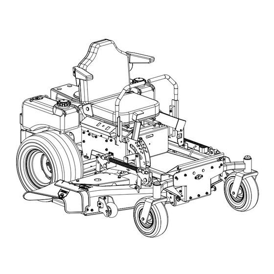
- Page 1 Hydrostatic Zero-Turn Residential Riding Mower Turf Equipment MODEL 23HP Z-Force 60 OPERATOR’S AND SERVICE MANUAL...
-
Page 2: Table Of Contents
TABLE OF CONTENTS Foreword............. . . 3 General Safety Operations . -
Page 3: Foreword
FOREWORD The Hydrostatic Zero-Turn Riding Mower provides superb maneuverability and mid-mount cut- ting. The machine incorporates many safety features that should be studied by all operators before use. The list of safety precautions should receive particular attention. This manual presents all of the operating and maintenance instructions necessary to keep your mower at peak efficiency. -
Page 4: General Safety Operations
RESULT IN PERSONAL INJURY. WHEN YOU SEE THIS SYMBOL- Your lawn mower was built to be operated according to the rules for safe operation in this manual. As with any type of power equipment, carelessness or error on the part DANGER of the operator can result in injury. -
Page 5: Slope Operation
Debris may build up on the mower deck or contact the engine exhaust presenting a potential fire hazard. 22. Use only accessories approved for this machine by Cub Cadet. Read, understand and follow all instructions provided with the approved accessory. B. SLOPE OPERATION... -
Page 6: D.service
Remove the key when the machine is left unattended to prevent unauthorized opera- tion. D. SERVICE Use extreme care in handling gasoline and other fuels. They are extremely flammable and the vapors are explosive. Use only an approved con- tainer. Never remove fuel cap or add fuel with the engine running. - Page 7 After striking a foreign object, stop the engine, remove the wire from the spark plug and thor- oughly inspect the mower for any damage. Repair the damage before restarting and operating the machine. 10. Grass catcher components are subject to wear, damage and deterioration, which could expose moving parts or allow objects to be thrown.
-
Page 8: Safety Decals
SAFETY DECALS WARNING SHIELD MISSING DO NOT OPERATE Part Number: 00030635 Part Number: 01003452 Part Number: 01003451 WARNING Engage parking brake when leaving the machine. Do not add fuel while the engine is hot or running. Stop engine, disconnect spark plug before adjusting or servicing. Before leaving operator's position: Disengage implement drive. -
Page 9: Specifications
SPECIFICATIONS GENERAL INFO. Controls: Engine ignition and start switch; throttle; choke; left and right steering levers; electric blade clutch switch; parking brake; mower deck lift Parking Brake: Internal, mechanical linkage attached to the brake handle Seat: Adjustable seat with armrests. 5" Adjustment (fore-aft) Frame: 2”... -
Page 10: Operating Instructions
OPERATING INSTRUCTIONS Figure. 1 Tach and Electric Blade Hour Meter Clutch Switch Ignition Switch A.General 1. When Mowing: a. Keep adults, children, and pets away from the area to be mowed. b. When operating this mower, in the forward direction, do not allow the steering levers to return to Neutral on their own. -
Page 11: Controls
b. Avoid turning downhill if possible, if not use extra care and go slowly. c. Avoid turning when going downhill, traction is at a minimum going downhill. d. Do not operate with discharge side of the mower toward streets, buildings, play- grounds, parking lots, other machines, ani- mals, and other people. - Page 12 Steering Levers Deck Lift Handle Brake Figure. 3 4. Electric Blade Clutch Switch: (See Figure 1.) Located on the right side of the mower beside the ignition switch. This is an “on/off” push pull switch that controls the electric blade clutch which supplies power to the cut- ting blades through the PTO.
-
Page 13: Initial Adjustments
C.Initial Adjustments 1. Check the fluid levels and tires: Note: These checks should be made daily, before starting the engine. a. Fuel: Using a good grade of unleaded, regular gasoline (for a gasoline engine), fill the fuel tank (beside the engine on the left or right side of the mower). -
Page 14: Zero Turn Break-In And Operating Procedures
desired cutting height has been attained. If the dimensions are not correct, repeat steps “c.” through “f.” above. 5. Lubricate all fittings listed in the mainte- nance section. D. Zero Turn Break-In And Operating Procedures DANGER: Reread the “When Mowing” Safety Precautions. The following procedures are suggested for opera- tors of ride-on machines which have zero turn capabilities. - Page 15 (toward center of machine). Slowly, move both lap bars toward the front of the machine until the machine begins to move forward — release the lap bars and the machine should stop. The more that the lap bars are moved toward the front of the machine, the faster the machine will move in the forward direc- tion.
-
Page 16: E.mower Cutting Blades
Gasoline Engine: Once the engine starts, push the choke on halfway and as the engine warms, push the choke off all the way. 4. Operating the Mower: Operating a zero-turn- ing-radius mower is not like operating a trac- tor-type riding mower. The zero-turning-radius mower is much more maneuverable and much less fatiguing to operate. -
Page 17: Maintenance And Service
Figure. 6 MAINTENANCE AND SERVICE WARNING: Disconnect the spark plug wires or remove the key from the ignition to prevent the engine from accidentally starting before performing any maintenance on this mower. A. Mower Deck 1. Removing the Mower Deck: a. -
Page 18: Changing Blade Drive Belts
Cover Plate Spindle Figure. 7 Note: Blades that cannot be easily bal- anced—REPLACE. 3. Changing the Blade Drive Belts: a. Set the parking brake. Remove ignition key and both spark plug caps. b. Unscrew the wing nuts from the deck cov- ers and remove both covers. -
Page 19: Electrical System
c. Remove the mower deck. See Mower Deck on page 17. d. Raise the seat forward to expose the hydraulic oil fill point. e. Clean the area around the hydraulic fill oil cap. Remove hydraulic fill oil cap. g. Place a suitable container (at least 2 gal- lon) under the hydraulic reservoir and the transaxels. - Page 20 dard plug-in type automotive fuse rated at 20.0 amp. 7. Safety Switches: There are five safety switches in the electrical circuit which control the engine. They are (1) the blade clutch switch, (2) the parking brake switch, (3) the left and (4) the right steering lever switches and (5) the seat switch.They operate so that in order to start the engine, the blade clutch switch must be off, the parking brake must be...
-
Page 21: Tires
the seat switch, the blade clutch switch and the electric blade clutch. Then check out the seat switch, the blade clutch switch and finally the electric blade clutch. D.Tires The two front wheels are caster wheels that are free to swivel to accommodate the direction of the Mower. The two rear wheels are used to propel the Mower in the direction of input from the drive handles. -
Page 22: Hydraulic System
If oil appears foamy or contains excessive air bubbles, DO NOT OPERATE UNIT. Contact Cub Cadet Service Dealer. 3. Hydrostatic Transmissions and motors: The pumps are the hardest-working compo- nents in the hydraulic system. They are in operation all the time the engine is running. -
Page 23: G.storage
rear. To make the adjustment, place the steer- ing levers in the opened-out neutral position and set the parking brake, shutoff the engine, take the key from the ignition switch and pivot the seat forward. If the mower creeps to the right, you will adjust the linkage on the left side of the mower and vice-versa. -
Page 24: Maintenance Schedule
MAINTENANCE SCHEDULE A. Daily Checks 1. Before starting engine: a. Check the fuel level. b. Check the engine oil level. c. Check the hydraulic oil level. d. Check the hydraulic hoses for leaks, abra- sion, kinks, twists, or a flattened condition. e. -
Page 25: Lubrication Chart
OIL CHART Apply a few drops of SAE 15W40 oil or use a spray lubricant. Apply the oil to both sides of pivot points. Wipe off any excess. Start engine and operate mower briefly to insure that oil spreads evenly. Number of Oil Points Description DAILY... -
Page 26: Performance Adjustments
Performance Adjustments A. High Speed Tracking Adjustment If mower tracks to one side with both lap bars in fully forward position: Check air pressure in all four tires: a. Pressure should be within specified ranges and balanced side-to-side. b. Rear tires 8-10 psi. recommended (20 psi MAX.) c. -
Page 27: Deck Corner Ball Wheel Roller Settings
C. Deck Corner Ball Wheel Roller Settings Matching the set heights of the ball rollers on the four corners of the mower deck to the desired cut height will prevent edge scalping and minimize any side-to-side variance in cut height. There are three height adjustment holes in the bracket that mount the ball rollers to the deck. -
Page 28: F.deck Leveling
F. Deck leveling Procedure Park the mower on a flat paved surface, engage the parking brake, shut off the engine, remove the key from the ignition switch, disconnect the spark plug wires and using the transport lever, lower the mowing deck into the 4" height of cut position. -
Page 29: Wiring Diagram
WIRING DIAGRAM GD: 02000167... -
Page 30: Slope Gauge
SLOPE GAUGE... -
Page 32: Warranty
There is no other express warranty. Contact your authorized Cub Cadet servicing dealer who sold you your Cub Cadet equipment. If this dealer is not available, see the Consumer Yellow Pages under “lawn mowers” for the name of a dealer near you.
Need help?
Do you have a question about the 23HP Z-Force 60 and is the answer not in the manual?
Questions and answers