Table of Contents
Advertisement
Quick Links
Harman Kardon
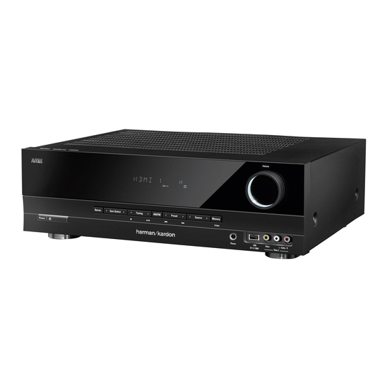
AVR 70/230
5x75W 5.1 CHANNEL A/V RECEIVER
ESD WARNING
OWNER'S MANUAL
Exploded View AND PARTS
PARTS LIST
Released EU2012
CONTENTS
2
SEMICONDUCTOR PINOUTS
3
PCB DRAWINGS
29
BLOCK DIAGRAMS
30
33
SCHEMATIC DIAGRAMS
Harman Consumer Group, Inc.
8500 Balboa Boulevard
Northridge, California 91329
Service Manual
46
63
74
78
79
Rev 0, 06/2012
Advertisement
Table of Contents
Troubleshooting

Related Manuals for Harman Kardon AVR 70/230


Summary of Contents for Harman Kardon AVR 70/230
- Page 1 Harman Kardon Service Manual AVR 70/230 5x75W 5.1 CHANNEL A/V RECEIVER CONTENTS ESD WARNING SEMICONDUCTOR PINOUTS OWNER’S MANUAL PCB DRAWINGS EXPLODED VIEW AND PARTS BLOCK DIAGRAMS TROUBLESHOOTING WIRING DIAGRAM PARTS LIST SCHEMATIC DIAGRAMS Released EU2012 Harman Consumer Group, Inc. Rev 0, 06/2012...
- Page 2 harman/kardon Service manual AVR745EU Some semiconductor (solid state) devices can be damaged easily by static electricity. Such components commonly are called Electrostatically Sensitive (ES) Devices. Examples of typical ES devices are integrated circuits and some field effect transistors and semiconductor "chip" components. The following techniques should be used to help reduce the incidence of component damage caused by static electricity.
- Page 3 AVR 700/AVR 70/AVR 70C Audio/video receiver Owner’s Manual...
-
Page 4: Table Of Contents
AVR 700/AVR 70/AVR 70C Table of Contents IntroductIon operAtIng your AVr SupplIed AcceSSorIeS controllIng the Volume ImportAnt SAfety InformAtIon mutIng the Sound plAce the AVr lIStenIng through heAdphoneS front-pAnel controlS SelectIng A Source reAr-pAnel connectorS VIdeo troubleShootIng tIpS SyStem remote control functIonS lIStenIng to fm And Am rAdIo IntroductIon to home theAter lIStenIng to medIA on A uSb deVIce... -
Page 5: Introduction
Thank you for choosing this Harman Kardon product! Verify Line Voltage Before Use for more than fifty years, the harman kardon mission has been to share a passion for music the AVr 700 has been designed for use with 120-volt alternating current (Ac). the and entertainment, using leading-edge technology to achieve premium performance. -
Page 6: Front-Panel Controls
If a short circuit is not found, bring the unit to an authorized harman kardon service center for inspection and repair before using Power On/Standby button: press this button to turn the AVr on and put it into the it again. -
Page 7: Rear-Panel Connectors
AVR 700/AVR 70/AVR 70C Rear-Panel Connectors Rear-Panel Connectors digital Audio hdmI composite Video Ac Input ® connectors connectors connectors connector radio Antenna Analog Audio Subwoofer Speaker connectors connectors connector connectors Radio Antenna connectors: connect the included Am and fm antennas to their Subwoofer connector: connect this jack to a powered subwoofer that has a line-level respective terminals for radio reception. -
Page 8: System Remote Control Functions
AVR 700/AVR 70/AVR 70C System Remote Control Functions Remote Control Functions Ir transmitter lens mute button power on button power off button AVr button Source Selector buttons Stereo mode button tone controls button Surround mode Select buttons Volume up/down buttons display mode button test tone Sequence button Audio Input Select button... - Page 9 1, optical digital 2, coaxial digital, In addition to controlling the AVr, the AVr remote can also control a harman kardon blu- hdmI (for hdmI 1 – hdmI 3 only) and Analog. this button does not function for the Am/ ray disc ®...
-
Page 10: Introduction To Home Theater
Introduction to Home Theater AVR 700/AVR 70/AVR 70C and Place Your Speakers Introduction to Home Theater Place Your Speakers this introductory section will help you to familiarize yourself with some basic concepts determine the locations for your system’s speakers according to their manufacturer’s unique to multichannel surround-sound AVrs, which will make it easier for you to set up directions and the layout of your listening room. -
Page 11: Types Of Home Theater System Connections
Types of Home Theater AVR 700/AVR 70/AVR 70C System Connections Types of Home Theater System Connections Subwoofer Connections the subwoofer is a speaker dedicated to reproducing only the low (bass) frequencies, there are different types of audio and video connections used to connect the AVr to your which require more power. -
Page 12: Video Connections
Types of Home Theater System AVR 700/AVR 70/AVR 70C Connections, continued Radio Connections Digital Audio Connections – Optical optical digital audio connectors are normally covered by a shutter to protect them from your AVr uses separate terminals for the included fm and Am antennas. the fm antenna dust. -
Page 13: Making Connections
AVR 700/AVR 70/AVR 70C Making Connections Making Connections Connect Your TV or Video Display HDMI Monitor Out connector If your tV has an hdmI connector and you have hdmI or component video source CAUTION: Before making any connections to the AVR, ensure that the AVR’s AC devices, use an hdmI cable (not included) to connect your tV to the AVr’s hdmI monitor power cord is unplugged from the AVR and the AC outlet. - Page 14 AVR 700/AVR 70/AVR 70C Making Connections, continued HDMI devices Optical digital audio devices If any of your source devices have hdmI connectors, using those connectors will provide If your source devices have optical digital outputs, connect them to the AVr’s optical the best possible video and audio performance quality.
-
Page 15: Connect The Radio Antennas
AVR 700/AVR 70/AVR 70C Making Connections, continued Audio recorders Connect to AC Power connect an analog audio recorder’s inputs to the AVr’s analog audio tape out connectors. connect the Ac power cord to the AVr’s Ac Input connector and then to a working Ac you can record any analog audio input signal except for the tape 1 input. -
Page 16: Using The On-Screen Menu System
AVR and unplug it. Check all speaker wires for a short circuit (“+” and “–” wires touching). If none is found, bring the unit to an authorized Harman Kardon service center for inspection and repair before using it again. -
Page 17: Additional Setup Menu Items
AVR 700/AVR 70/AVR 70C Set Up the AVR, continued Notes on Setting Subwoofer Volume: consult the technical specifications for your system’s main left and right speakers and locate the frequency response, usually given as a range, e.g., 80hz – 20khz (±3db). •... -
Page 18: Operating Your Avr
AVR 700/AVR 70/AVR 70C Operating Your AVR Operating Your AVR In the fm Stereo mode, the radio uses automatic tuning, meaning each press of the tuning up/down buttons scans until a station with acceptable signal strength is found. In the fm mono mode, the radio uses manual tuning, in which each press of a tuning button now that you have installed your components and completed a basic configuration, you steps through a single frequency increment. -
Page 19: Configure The Avr For Your Speakers
Operating Your AVR, continued, AVR 700/AVR 70/AVR 70C and Advanced Functions Selecting a Surround Mode Surround Mode Selection Surround-mode selection depends upon the format of the incoming audio signal as well Selecting a surround mode can be as simple or sophisticated as your individual system as your personal taste. -
Page 20: Sleep Timer
If the AVr does not function correctly after a processor reset, contact an authorized harman kardon service center for assistance. to locate an authorized service center, If you press the Sleep button after the timer has been set, the remaining play time will be visit our web site at www.harmankardon.com. -
Page 21: Troubleshooting
• Amplifier is in protection mode due to internal problems • Contact your local Harman Kardon service center no sound from center or surround speakers • Incorrect surround mode • Select a surround mode other than stereo •... -
Page 22: Specifications
AVR 700/AVR 70/AVR 70C Specifications Specifications Audio Section Video Section multichannel power: 75w per channel, two television format: ntSc (AVr 700); channels driven @ 6 pAl (AVr 70/AVr 70c) ohms, 20hz – 20khz, Input level/impedance: 1Vp-p/75 ohms <0.1% thd; 100w per channel, two output level/impedance: 1Vp-p/75 ohms channels driven @ 6... -
Page 23: Appendix
AVR 700/AVR 70/AVR 70C Appendix Appendix – Default settings, worksheets, remote product codes Table A1 – Recommended Source Component Connections Device Type AVR Source Audio Connections Video Connections Vcr, dVr, pVr, or other audio/video recorder Video 1 • Video 1 Analog (inputs and outputs) •... - Page 24 AVR 700/AVR 70/AVR 70C Appendix Table A4 – Surround Modes Surround Mode Description Incoming Bitstream or Signal • Dolby Digital 1/0/.0 or .1, 2/0/.0 or .1, 3/0/.0 or .1, dolby digital provides up to five separate main audio channels and a dedicated low-frequency 2/1/.0 or .1, 2/2/.0 or .1, 3/2/.0 or .1 effects (lfe) channel.
- Page 25 AVR 700/AVR 70/AVR 70C Appendix Table A4 – Surround Modes (cont.) Surround Mode Description Incoming Bitstream or Signal • DTS 1/0/.0 or .1, 2/0/.0 or .1, 3/0/.0 or .1, 3/1/.0 or .1, 2/2/.0 or dtS Stereo delivers a 2-channel downmix of dtS digital materials or presents a matrix- .1, 3/2/.0 or .1 encoded surround presentation.
- Page 26 AVR 700/AVR 70/AVR 70C Appendix refer to the numbered buttons when using the remote control function list...
- Page 27 AVR 700/AVR 70/AVR 70C Appendix Table A5 – Remote Control Function List Button Name AVR Function Blu-ray/DVD Button Name AVR Function Blu-ray/DVD power on power on power on power off power off power off mute mute mute AVr Select AVr Select hdmI 1 hdmI 1 Select hdmI 1 Select...
- Page 28 8500 balboa boulevard, northridge, cA 91329 uSA © 2012 hArmAn International Industries, Incorporated. All rights reserved. harman kardon is a trademark of hArmAn International Industries, Incorporated, registered in the united States and/or other countries. blu-ray disc is a trademark of the blu-ray disc Association.
- Page 30 AVR70/700/70C TROUBLESHOOTING Symptom Cause and Remedy Ref No. Power On Failure A) AC-Cord check. 1. FLT does not light up. B) Power Trans (Main/ST-BY) check. 2. ST-BY LED does not light up. C) Fuse's disconnection check. F300(STANDBY) D) Connector's disconnection or disjunction. Change or close insertion of the connector.
- Page 31 Symptom Cause and Remedy Ref No. Sounds from Speaker when A) NOT Supported Headphone Detect. Headphone's connected. Push the Speaker On/Off Button(Speaker off). Bass / Treble Control Failure. A) Volume IC check. I.C109(MAIN) 1. Resister/Capacitor correction figure check.(Bass) I.C109 PIN No. ( 26,27,32,33)(MAIN) 2.
- Page 32 Remote Controller Failure. A) Battery check. B) RMC I.C & Resonator inferior. 1. μ-COM I.C B+( 3.3 )V check. I.C119 Pin No. ( 16,62 )(DMAIN) RMC701(1) (FRONT) 2. REMOCON data check. FM Failure. A) FM MUTE adjustment inferior. B) FRONT-END inferior. C) FM DET COIL inferior.
- Page 33 4000040201010S FOOT RUBBER 4007040201060S FOOT 5080211793000S PLATE KNOB VOLUME BK 5077212543020S FRONT WINDOW ACRY AVR70 5080211793000S KNOB VOLUME MILKY 5087211781100S KNOB VOLUME CAP AVR 70 5097213651100S FUNCTION BUTTON (7) 5200210262000S FILTER FIP, WINE COLOR 6007212260010S GIFT BOX BEAUTY CARTON AVR 70/230...
- Page 34 AVR 70 amplifier board parts list DESCRIPTION REF NO. Q'TY PART NO. P.C.B TOTAL ASSY 1 7025-HK112-101-2 P.C.B SUB ASSY 1 7028-06684-101-0 P.C.B 1 7020-06684-000-0S P.C.B INS ASSY AVR133(HARMAN)/AMP-AXIAL 1 7027-06684-1A1-0 P.C.B INS ASSY AVR133(HARMAN)/AMP-MANUAL 1 7027-06684-1M1-0 P.C.B INS ASSY AVR133(HARMAN)/AMP-RADIAL 1 7027-06684-1R1-0 COILS...
- Page 35 AVR 70 control board parts list DESCRIPTION REF NO. Q'TY PART NO. P.C.B TOTAL ASSY 1 7025-HK112-101-5 P.C.B SUB ASSY 1 7028-07210-101-0 P.C.B 1 7020-07210-000-0S P.C.B INS ASSY CNT-AXIAL 1 7027-07210-1A1-0 P.C.B INS ASSY CNT-MANUAL 1 7027-07210-1M1-0 P.C.B INS ASSY CNT-RADIAL 1 7027-07210-1R1-0 P.C.B INS ASSY...
- Page 36 AVR 70 front board parts list DESCRIPTION REF NO. Q'TY PART NO. CN707 CN,WIRE 2MM 250/5P 20010HS-05=CKM2002H-05 WH2547,1533#26SHLD 1 L002-25105-007-0S J700-J714 CN,WIRE 1P JUMPER (0.6/52MM) 15 L045-08400-604-0S CP704 CN.WAFER 2.5MM 5268-03A 3P ANGLE 1 L102-52680-301-0S CP701 CN.WAFER 2.0MM 20010WS-04A00 DIP4P STRAIGHT 1 L101-20010-041-0S FPC701 CN.FPC 1.25MM...
- Page 37 AVR 70 HDMI board parts list DESCRIPTION REF NO. Q'TY PART NO. P.C.B TOTAL ASSY HDMI 1 7025-HK112-101-1 P.C.B SUB ASSY HDMI 1 7028-07208-301-0 P.C.B HDMI 1 7020-07208-020-0 P.C.B INS ASSY HDMI-MANUAL 1 7027-07208-3M1-0 P.C.B INS ASSY HDMI-SMD 1 7027-07208-3S1-0 COILS L100-L114 COIL,BEAD...
- Page 38 AVR 70 HDMI board parts list DESCRIPTION REF NO. Q'TY PART NO. C110/C118/C129/C131 C,ELECT CHIP(GE) 10UF-MVG/16V,3.3*3.7*5.2 REEL (Z8154) SY 4 D050-10008-347-0S C180/C232/C356/C360 C,ELECT CHIP(GE) 10UF-MVG/16V,3.3*3.7*5.2 REEL (Z8154) SY 4 D050-10008-347-0S C370-C374 C,ELECT CHIP(GE) 10UF-MVG/16V,3.3*3.7*5.2 REEL (Z8154) SY 5 D050-10008-347-0S C162/C191/C193/C198 C,ELECT CHIP(GE) 100UF-MVG/6.3V,5.3*5.9*5.3 3REEL (Z8156) SY 4 D050101081650S...
- Page 39 AVR 70 HDMI board parts list DESCRIPTION REF NO. Q'TY PART NO. R133-R137 R,CHIP THICK 0-J , 1/16W 5 C200-00006-M10-1S R140/R156/R169/R176 R,CHIP THICK 0-J , 1/16W 4 C200-00006-M10-1S R190/R200-R202 R,CHIP THICK 0-J , 1/16W 4 C200-00006-M10-1S R421/R459-R463/R482 R,CHIP THICK 0-J , 1/16W 7 C200-00006-M10-1S R526/R527 R,CHIP THICK...
- Page 40 AVR 70 HDMI board parts list DESCRIPTION REF NO. Q'TY PART NO. R148/R314 R,CHIP THICK 470-J , 1/16W 2 C200-04716-M10-1S R207/R211/R244/R245 R,CHIP THICK 4.7K-J , 1/16W 4 C200-04726-M10-1S R248/R250/R267/R271 R,CHIP THICK 4.7K-J , 1/16W 4 C200-04726-M10-1S R376/R377/R483/R484 R,CHIP THICK 4.7K-J , 1/16W 3 C200-04726-M10-1S R513/R525 R,CHIP THICK...
- Page 41 AVR 70 main board parts list DESCRIPTION REF NO. Q'TY PART NO. C264 C,ELECT GE 85C 100UF-M/16V,6.3*11-5RE,SMS SY 1 D040-10108-307-0S C167 C,ELECT GE 85C 2.2UF-M/50V,5*11-5RE SMS SY (Pb Free) 1 D040-2R208-716-0S C193/C195 C,ELECT GE 85C 330UF-M/10V,6.3*11-5RE,SHL-SY 2 D040-33108-207-0S C131/C139 C,ELECT GE 85C 47UF-M/16V,5*11-5RE.SMS SY 2 D040-47008-308-0S C145SW/C146SW...
- Page 42 AVR 70 main board parts list DESCRIPTION REF NO. Q'TY PART NO. D137 D,SWITCHING 1N4148M-52RE 75V 150MA 1 K000-41480-252-0S D111/D112 D,RECTIFIER BRIDGE KBPC604 6A 2 K047604000020S INTEGRATED CIRCUIT IC105 IC,LINEAR OP UTC4580E SOP8 DUAL OP AMP 1 J121-45800-101-0S IC106 IC,MONITOR SW IC LA7956 VIDEO SWITCH FOR TV/VCR USE SIP9P 1 J171795600010S IC109...
- Page 43 AVR 70 main board parts list DESCRIPTION REF NO. Q'TY PART NO. R254/R257 R,CHIP THICK 75-J , 1/16W 2 C200-07506-M16-0S R187 R,CHIP THICK 15K-J , 1/16W 1 C200-01536-M16-0S R243 R,CHIP THICK 100-J , 1/16W 1 C200-01016-M16-0S R205L/R R,CHIP THICK 1K-J , 1/16W 2 C200-01026-M16-0S R198 R,CHIP THICK...
- Page 44 AVR 70 main board parts list DESCRIPTION REF NO. Q'TY PART NO. PACK102 TUNER,FM/AM KST-MW004MV1-S63 FM/AM NA 1 E903-00410-002-0S WIRE101 CN,WIRE 140,100MM/2P SOLDER(7MM) RD,YL1007#18 TWIST 1 L000-14102-015-0S WIRE102 CN,WIRE 190MM/1P SOLDER(5MM),SOLDER(5MM) BK1007#18 1 L000-19101-007-0S WIRE103 CN,WIRE 175MM/3P SOLDER(5MM),SOLDER(5MM) YW1007#18 TWIST 1 L000-17103-007-0S GND101-GND104 TERMINAL...
- Page 45 AVR 70 standby board parts list DESCRIPTION REF NO. Q'TY PART NO. R304 R,METAL FILM 100PPM 10-J,1/4W-R.REEL 1 C060-01006-305-0S R300 R,CHIP THICK 10K-J,1/16W-1608REEL 1 C200-01036-M16-0S R301 R,CHIP THICK 20K-J,1/16W-1608REEL 1 C200-02036-M16-0S R333 R,CHIP THICK 47K-J,1/16W-1608REEL 1 C200-04736-M16-0S R303 R,CHIP THICK 2.2K-J,1/16W-1608REEL 1 C200-02226-M16-0S J304...
- Page 46 User Guide — EPF011C_UG 2.2 Pin Diagram Figure 2-2 EPF011C Pin Diagram P7[0](RXD) P1[1] P7[1](TXD) P8[7](PWM) P4[1] P2[1] P3[0] P3[1] P3[4] X_OUT P3[5] X_IN RSTb Explore Microelectronics Inc. Explore Microelectronics Inc. Explore Microelectronics Inc. Explore Microelectronics Inc. Explore Microelectronics Inc. Explore Microelectronics Inc.
- Page 47 User Guide — EPF011C_UG 2.3 Pin Description Unless otherwise stated, unused input pins must be tied to ground, and unused output pins left open. Table 2-1 Pin Description Name In/Out Buffer Type Description Chip operation mode. 0: Normal mode OP_MODE IXDXXP 1: ICP (In Circuit Flash Programming) mode NOTE: The input crystal rate will be 24MHz if this ICP mode is used.
- Page 48 Integrated Circuit (R2A15218FP) Fig 1. BLOCKDIAGRAM AND PIN CONFIGURATION(TOP VIEW) AVCC MUTE AVCC N.C. AVEE AVEE N.C. TREL 0/-6/-12/-18dB ADCL BASSL2 ADCR BASSL1 N.C. AGND Bass/ Treble 0~-95dB, -14~+14dB -∞ +42~0dB MAIN N.C. (2dB step) (0.5dBstep) Bypass (0.5dBstep) Tone INR1 FROUT Tone+MIX Tone...
- Page 49 Integrated Circuit (R2A15218FP) Fig 2. PIN DESCRIPTION PIN No. Function Name 23,21, FROUT,FLOUT, 17,15, COUT,SWOUT, Output pin of FL/FR/C/SW/SL/SR/SBL/SBR channel 11,9, SROUT, SLOUT, SBROUT,SBLOUT 24,20, FRC,FLC, 18,14, CC,SWC, Connects capacitor for reducing click noise of 12,8, SRC,SLC, L/R/C/SW/SL/SR/SBL/SBR channel volume SBRC,SBLC 4,7,10,16, Analog ground of internal circuit...
- Page 50 [AK4588] ■ PVSS PVDD X'tal Clock Oscillator 8 to 3 Recovery Clock MCKO1 Generator Input MCKO2 Selector LRCK2 DAIF Audio BICK2 Decoder SDTO2 DAUX2 AVDD AVSS DVDD Error & CCLK Q-subcode DVSS AC-3/MPEG μP I/F STATUS buffer CDTO TVDD Detect Detect CDTI INT0...
- Page 51 [AK4588] ■ -40 ∼ +85°C AK4588VQ 80pin LQFP(0.5mm pitch) AKD4588 ■ LOUT3 ROUT4 PVSS LOUT4 PVDD DZF1 DZF2 (Top View) TEST2 MASTER CAD0 XTL0 XTL1 CAD1 SDTI1 SDTI2 SDTI3 DAUX2 SDTI4 DAUX1 MCLK CDTI/SDA CCLK/SCL INT0 MS0287-J-03 2009/05 - 4 -...
- Page 52 [AK4588] Pin Name Function INT1 Interrupt 1 Pin Block-Start Output Pin for Receiver Input BOUT “H” during first 40 flames. TVDD Output Buffer Power Supply Pin, 2.7V∼5.5V Digital Power Supply Pin, 4.5V ∼ 5.5V DVDD DVSS Digital Ground Pin X'tal clock Output Pin X'tal / External clock Input Pin Test 3 Pin TEST3...
- Page 53 [AK4588] Pin Name Function Power-Down Mode Pin When “L”, the AK4588 is powered-down, all output pin goes “L”, all registers are reset. When CAD1-0 pins are changed, the AK4588 should be reset by the PDN pin. Master Mode Select Pin MASTER “H”: Master mode, “L”: Slave mode Zero Input Detect 2 Pin...
- Page 54 [AK4588] Pin Name Function Analog Power Supply Pin, 4.5V∼5.5V AVDD Analog Ground Pin, 0V AVSS Receiver Channel 0 Pin (Internal biased pin. Internally biased at PVDD/2) No Connect pin No internal bonding. This pin should be connected to PVSS. Receiver Channel 1 Pin (Internal biased pin. Internally biased at PVDD/2) Test 1 Pin TEST1 This pin should be connected to PVSS.
-
Page 55: Device Overview
TMS320DA810/808/807/805 www.ti.com SPRS595 – JANUARY 2010 Pin Assignments Extensive use of pin multiplexing is used to accommodate the largest number of peripheral functions in the smallest possible package. Pin multiplexing is controlled using a combination of hardware configuration at device reset and software programmable register settings. 3.5.1 Pin Map (Bottom View) Figure 3-3 Figure 3-4... - Page 56 TMS320DA810/808/807/805 SPRS595 – JANUARY 2010 www.ti.com RSV2 EMB_SDCKE USB0_VDDA12 USB0_VDDA18 EMB_CLK EMB_WE_DQM[1]/GP5[14] USB0_DP EMB_D[8]/GP6[8] USB0_DM EMB_D[9]/GP6[9] EMB_D[10]/GP6[10] USB0_VDDA33 PLL0_VDDA EMB_D[11]/GP6[11] PLL0_VSSA EMB_D[12]/GP6[12] OSCIN EMB_D[13]/GP6[13] OSCVSS OSCOUT EMB_D[14]/GP6[14] RESET EMB_D[15]/GP6[15] RTC_XI EMB_D[0]/GP6[0] RTC_CVDD EMB_D[1]/GP6[1] TRST EMB_D[2]/GP6[2] EMB_D[3]/GP6[3] (177) EMB_D[4]/GP6[4] Thermal Pad GP7[14] EMB_D[5]/GP6[5] EMB_D[6]/GP6[6]...
- Page 57 PIN CONFIGURATION (top view) P4_4/CS0 P0_7/AN0_7/D7 P4_5/CS1 P0_6/AN0_6/D6 P0_5/AN0_5/D5 P4_6/CS2 P0_4/AN0_4/D4 P4_7/CS3 P0_3/AN0_3/D3 P5_0/WRL/WR P0_2/AN0_2/D2 P5_1/WRH/BHE P0_1/AN0_1/D1 P5_2/RD P0_0/AN0_0/D0 P5_3/BCLK P10_7/AN7/KI3 P5_4/HLDA P10_6/AN6/KI2 P5_5/HOLD P10_5/AN5/KI1 P5_6/ALE P10_4/AN4/KI0 P5_7/RDY/CLKOUT P10_3/AN3 P6_0/CTS0/RTS0 P10_2/AN2 P6_1/CLK0 P6_2/RXD0/SCL0 P10_1/AN1 P6_3/TXD0/SDA0 AVSS P10_0/AN0 P6_4/CTS1/RTS1/CTS0/CLKS1 VREF P6_5/CLK1 AVCC P6_6/RXD1/SCL1 P6_7/TXD1/SDA1...
- Page 58 Performance Outline Table 1.1 lists Performance Outline of M16C/30P Group. Table 1.1 Performance Outline of M16C/30P Group Item Performance Number of Basic Instructions 91 instructions 62.5ns(f(XIN)=16MHz, VCC1=VCC2=3.0 to 5.5V, no Minimum Instruction wait) Execution Time 100ns(f(XIN)=10MHz, VCC1=VCC2=2.7 to 5.5V, no wait) Single-chip, memory expansion and microprocessor Operation Mode mode...
-
Page 59: Pin Configuration
PRELIMINARY W9864G6JH 3. AVAILABLE PART NUMBER SELF REFRESH OPERATING PART NUMBER SPEED CURRENT (MAX.) TEMPERATURE 0°C ~ 70°C W9864G6JH-5 200MHz/CL3 2 mA W9864G6JH-6 166MHz/CL3 2 mA 0°C ~ 70°C W9864G6JH-6I 166MHz/CL3 2 mA -40°C ~ 85°C W9864G6JH-7 143MHz/CL3 2 mA 0°C ~ 70°C 0°C ~ 70°C W9864G6JH-7S... - Page 60 PRELIMINARY W9864G6JH 5. PIN DESCRIPTION PIN NUMBER PIN NAME FUNCTION DESCRIPTION Multiplexed pins for row and column address. Row address: A0−A11. Column address: A0−A7. 23 ~ 26, 22, Address A0−A11 A10 is sampled during a precharge command to 29 ~35 determine if all banks are to be precharged or bank selected by BS0, BS1.
- Page 76 Q2034 FDC608PZ Q2035...
- Page 77 MAIN TRANS S1(AMP B+/B-) S2(+12V,-12V, DSP, HDMI) AC CORD S3(FLT) SUB TRANS...
- Page 82 ST-BY B'D CP305 F301 R304 OPTION 10(1/4) GP5A-1 F300 OPTION R303 USA ONLY Q301 Q302 KTC3875S KRC107S +3V3(ST/BY) +3V3(ST/BY) ZD301 5V_IN MTZ3.0B CP304 PWR S/W D303 ST RLY KDS4148U IC300 KIA1117S33 ST/BY TRANS R302 CN301 D304 KDS4148U PT301 D305 1N4007 D307 1N4007 AC CORD...
- Page 83 PREOUT_SW C164SW100P-J FROM BD106 R160SW 100K BD108 FRONT B'D BD107 Q115 R252 R251 KTC2875B CHASISS GND BD109 ZD101 10N(EB)-100V 10N(EB)-100V 10N(EB)-100V 10N(EB)-100V 10N(EB)-100V BD110 R258 C161SL V3_R UDZ7.5B C161SR C161C C161L C161R C415 C251 100N-K R255 V3_L Q114 220P-J KTC2875B ZD102 V_GND UDZ7.5B...
- Page 84 Q113 R651 KRA105S R613 R620 C604 10/16(3*5) R637 R130 470K C129 100N Q573 INC2001AC1 Q572 INC2001AC1 R635 R625 C608 R622 10/16(3*5) Q112 R655 KRA105S R644 FROM R643 C214 1N-K MAIN B'D C623 L121 BD121T JACK106 C199 100/10 10/16(3*5) R648 R131 470K L125 BD121T...
- Page 85 Q101 C100 KRC104S R105 2.2/50-Z8154 XTAL100 18M432MHZ R107 C102 OPEN R540 R108 OPEN OPEN R109 C108 1/50-Z8155 L102 R112 BEAD R201 5.6K R113 C110 L103 C109 100N R114 10/16-Z8154 BEAD R115 C111 100N C112 R204 100N R118 R491 R120 R119 OPEN R492 R121...
- Page 86 L122 LBC2012T-4.7UH R208 R209 300K C172 IC108 74VHCU04 BEAD L125 C173 L124 LBC2012T-4.7UH R212 R213 R214 R215...
- Page 87 R221 L129 BEAD-2012 L130 2.2UH L131 C191 100/6.3-Z8156 BD121T L132 L133 LBC2012T-4.7UH BEAD-2012 L134 INT1 R227 LBC2012T-4.7UH BOUT XTAL102 C203 TVDD 24M576 100/6.3-Z8156 DVDD R527 80.INT0 DVSS AVSS C209 61.RX2 10N-K AVDD 60.TEST1 VREFH C211 C212 R229 TEST3 OPEN VCOM OPEN C210 MCKO2...
- Page 88 CP100 20010WS-05 R264 R265 C2327 - C500 FAULT 1000N-K IC111 IL1117-1.2 R552 47K R270 R553 0-2012 L137 IC2024 BEAD TPS2557 CP106 OPEN Q109 RT1N141C C246 C241 220/6.3-Z8157 IC114 220/6.3-Z8156 L141 IL1117-1.8 BKP_HS101-2125 R295 L142 0-2012 BEAD DQ15 VDDQ GNDQ DQ14 DQ13 GNDQ D157...
- Page 89 C380 -30V +3V3 C378 Standby_on 100N KEY2 KEY3 FL_CE FL_CLK FL_DATA R548 VOL_UP VOL_DN R406 STBY_LED FL_SW R410 R413 R412 R416 OPEN P4_6 P0_5 50.P4_4 R422 R419 49.P4_5 R420 OPEN P4_7 P0_4 81.P0_7 R421 P5_0 82.P0_6 P0_3 R518 R423 P5_1 P0_2 R517 R424...
Need help?
Do you have a question about the AVR 70/230 and is the answer not in the manual?
Questions and answers