
Related Manuals for Harman Kardon AVR 7000


Summary of Contents for Harman Kardon AVR 7000
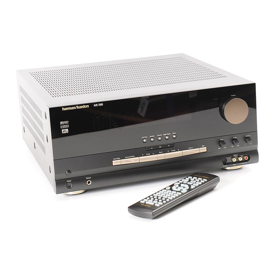
- Page 1 AVR 7000 Audio/Video Receiver OWNER’S MANUAL ® Power for the digital revolution. ™...
-
Page 2: Table Of Contents
AVR 7000 Audio/Video Receiver Introduction Safety Information Unpacking Front Panel Controls Front Panel Information Display Rear Panel Connections Main Remote Control Functions Zone II Remote Control Functions Installation and Connections System Configuration Input Setup Surround Setup Delay Settings Crossover Frequency... -
Page 3: Introduction
DVD and LD releases and Digital Television broadcasts. While complex digital systems are hard at work within the AVR 7000 to make all of this happen, hookup and operation are simple. Color-keyed connections, a backlit, programma- ble remote control, and on-screen menus make the AVR 7000 easy to use. -
Page 4: Safety Information
Safety Information Important Safety Information Verify Line Voltage Before Use Your AVR 7000 has been designed for use with 120-volt AC current. Connection to a line volt- age other than that for which it is intended can create a safety and fire hazard and may damage the unit. -
Page 5: Front Panel Controls
* Volume Control ( Set Button Ó Input Indicators to turn on the AVR 7000; press it again to turn the unit off. Note that the Power Indicator surrounding the switch 3 will turn green when the unit is on. - Page 6 Information Display Ò into the AVR 7000’s memory. The set button may also be used to change the display brightness. (See page 31.) Ó...
-
Page 7: Front Panel Information Display
On Screen Display is being used. N Night Mode Indicator: This indicator lights when the AVR 7000 is in the Night mode, which preserves the dynamic range of digital program material at low volume levels. - Page 8 X Mute Indicator: This indicator illuminates to remind you that the AVR 7000’s output has been silenced by pressing the Mute button f . Press the Mute button again to return to the previously selected output level.
-
Page 9: Rear Panel Connections
Rear Panel Connections ¡ ™ £ ¡ AM Antenna ™ FM Antenna £ 6-Channel Direct Inputs ¢ CD Inputs ∞ Component Video Outputs § Video 2 Component Video Inputs ¶ DVD Component Video Inputs • Tape Inputs ª Speaker Outputs ‚... - Page 10 AC device. The power will remain on at this outlet regard- less of whether the AVR 7000 is on or off. ‹ Switched AC Accessory Outlets: These outlets may be used to power any device that...
-
Page 11: Main Remote Control Functions
POWER MUTE TEST GUIDE DIGITAL EXIT VID 1 6 CH. VID 2 AM/FM VID 3 TUN-M VID 4 MEMORY LIGHT AVR 7000 kardon TAPE SLEEP VOL. SURR. MENU SPKR DELAY PREV.CH. NIGHT MULTI-ROOM DWN-TUNING-UP DWN-PRESET-UP DIRECT CLEAR 11 MAIN REMOTE CONTROL FUNCTIONS... - Page 12 In addition, the AVR 7000’s remote is shipped from the factory to operate the AVR 7000 and most Harman Kardon CD or DVD players and cassette decks. The remote is also capable of operating a wide variety of other products using the control codes that are part of the remote.
- Page 13 Sleep Button: Press this button to place the unit in the Sleep mode. After the time shown in the display, the AVR 7000 will auto- matically go into the Standby mode. Each press of the button changes the time until turn-off in...
-
Page 14: Zone Ii Remote Control Functions
14 ZONE II REMOTE CONTROL FUNCTIONS å Power Off: When used in the room where the AVR 7000 is located, press this but- ton to place the unit in Standby. When it is used in a remote room with a sensor that is connected to the Multi IR jack b, this button turns the Multi-Room system on and off. -
Page 15: Installation And Connections
Out jacks ‚ on the AVR 7000. 3. Connect the output of any digital sources to the appropriate input connections on the AVR 7000 rear panel. Note that the Optical and Coaxial digital inputs °· may be used with a Dolby Digital or DTS source or the output of a conventional CD or LD player’s... -
Page 16: Input Jacks
Composite Video Monitor Output e. 16 INSTALLATION AND CONNECTIONS System and Power Connections The AVR 7000 is designed for flexible use with multiroom systems, external control compo- nents and power amplifiers. Main Room Remote Control Extension If the receiver is placed behind a solid or... - Page 17 Installation and Connections External Audio Power Amplifier Connections If desired, the AVR 7000 may be connected to optional, external audio power amplifiers or used with equalizers or speaker systems that require connection between the preamp and amplifier sections of a receiver.
-
Page 18: System Configuration
System Configuration When all audio, video and system connections have been made, there are a few configuration adjustments that must be made. A few minutes spent to correctly configure and calibrate the unit will greatly add to your listening experience. Speaker Selection and Placement The placement of speakers in a multichannel home-theater system can have a noticeable... - Page 19 You are now ready to power up the AVR 7000 to begin these final adjustments. 1. Plug the Power Cable › into an unswitched AC outlet.
-
Page 20: Input Setup
Input Setup The first step in configuring the AVR 7000 is to select an input. This may be done by pressing the front panel Input Source Selector ! until the desired input’s name appears momen-... -
Page 21: Crossover Frequency
Main Information Display W. Crossover Frequency The crossover frequency is the point at which the AVR 7000 divides low frequency, or bass sounds, from the rest of the audio output. This is important as it enables you to match the per- formance of the AVR’s’... -
Page 22: Speaker Setup
MENU, and press the Set button i to return to the main menu. Speaker Setup The first few adjustments tell the AVR 7000 which type of speakers are in use. This is important as it adjusts the settings that deter- mine which speakers receive low frequency (bass) information. -
Page 23: Output Level Adjustment
Output level adjustment is a key part of the configuration process for any surround sound product. It is particularly important for a Dolby Digital receiver such as the AVR 7000, as correct outputs will ensure that you hear sound tracks with the proper directionality and intensity. - Page 24 Once the settings outlined on the previous pages have been made, the AVR 7000 is ready for operation. While there are some additional settings to be made, these are best done after...
-
Page 25: Operation
Bass Control # and Treble Control ^ to suit your listening tastes or room acoustics. • To set the output of the AVR 7000 so that the output is “flat, ” with the tone controls de- activated, press the Tone Mode button 6... -
Page 26: Surround Mode Chart
Operation Surround Mode Chart MODE FEATURES DOLBY DIGITAL Available only with digital input sources encoded with Dolby Digital data. It provides up to five separate main audio channels and a special dedicated Low Frequency Effects channel. Available only with digital input sources encoded with DTS data. Available on special DVD, LD and audio-only discs, DTS provides up to five separate main audio channels and a special dedicated low frequency channel. -
Page 27: Digital Audio Playback
(HDTV) system. Note that an optional, external RF demodulator is required to use the AVR 7000 to listen to the Dolby Digital sound tracks available on laser discs. Connect the RF output of the LD player to... -
Page 28: Night Mode
“Audio Select” button or in a menu screen on the disc) to send a full 5.1 feed to the AVR 7000. It is also possible for the type of sig- nal feed to change during the course of a DVD playback. -
Page 29: Tuner Operation
PCM (Pulse Code Modulation) is the non- compressed digital audio system used for compact discs and laser discs. The digital circuits in the AVR 7000 are capable of high quality digital-to-analog decoding, and they may be connected directly to the digital audio output of your CD or LD player. -
Page 30: Channel Direct Input
Operation Output Level Trim Adjustment Normal output level adjustment for the AVR 7000 is established using the test tone, as outlined on page 23. In some cases, however, it may be desirable to adjust the output levels using program material such as a test disc, or a selection you are familiar with. -
Page 31: Advanced Features
Switching the front panel jacks to output status is temporary and it will be cancelled when the AVR 7000 is turned off. When the unit is turned back on, the jacks will revert to the default sta- tus as an input. To return the front panel jacks... -
Page 32: Osd Settings
Note that this setting is temporary and will remain active only until it is changed or until the AVR 7000 is turned off. Once the unit is turned off, the semi-OSD displays will remain activated, even if they were switched off for the previous listening session. -
Page 33: Multiroom Operation
∂Ƀ. Once the multiroom system is turned on, it will remain on even if the AVR 7000 is placed in the Standby mode in the main room by press- ing the Power Off Button d or the System Power Control 2 on the front panel. -
Page 34: Programming The Remote
Auto Search Method. Auto Search Method If the unit you wish to include in the AVR 7000’s remote is not listed in the code tables in this manual or if the code does not seem to operate... -
Page 35: Learning Codes
Program Indicator light a turns orange and the red light under the device selector button turns red. Release the buttons. 4. Press the button on the AVR 7000 remote that you wish to program. Note that the Program Indicator light a will begin to flash continuously and the red light under the device selector will go out. -
Page 36: Programmed Device Functions
For example, button number 9 is the Test Tone but- ton for the AVR 7000, but it is the “Favorite” button for many cable television boxes and satellite receivers. Button number 35 is the... -
Page 37: Reassigning Device Control Selectors
SAT button again. Erasing Learned Command Codes The AVR 7000’s remote allows you to remove a single learned command from within a device’s command set, to remove all the learned com- mands for a single device, or to remove all the learned commands that are stored in the remote. -
Page 38: Function List
Function List No. Button Name Tape AVR Selector CD Selector Power On Tape Selector Aux/DVD Selector Power On Power Off Power Off Sleep CDP Select Volume Up Input Level Up Mute Test Input Select Surround Select CDR Select Volume Down Input Level Down Channel Select ⁄... -
Page 39: Setup Code Tables
Setup Code Tables: TV Manufacturer/Brand Setup Code Number ADMIRAL AKAI AMPRO ANAM CANDLE CAPEHART CENTRONIC CITIZEN CLASSIC CONCERTO CONTEC CRAIG CROWN CURTIS MATHES DAEWOO DAYTRON DWIN DYNATECH ELECTROHOME EMERSON FISHER FUNAI FUTURETECH GOLDSTAR HITACHI INFINITY INKEL 39 SETUP CODES... - Page 40 Setup Code Tables: TV (continued) Manufacturer/Brand Setup Code Number JC PENNEY JENSEN KENWOOD KLOSS LUXMAN MAGNAVOX MARANTZ MEMOREX METZ MINERVA MITSUBISHI OPTONICA PANASONIC PHILCO PHILIPS PIONEER PORTLAND PROSCAN PROTON QUASAR RADIO SHACK 40 SETUP CODES...
- Page 41 Setup Code Tables: TV (continued) Manufacturer/Brand Setup Code Number REALISTIC RUNCO SAMPO SAMSUNG SANYO SCOTT SEARS SHARP SIGNATURE SONY SOUNDESIGN SUPRE MACY SYLVANIA SYMPHONIC TANDY TATUNG TECHNICS TECHWOOD TEKNIKA TERA TOSHIBA TOTEVISION UNIVERSAL VIDEO CONCEPTS VIDIKRON VIDTECH WARDS YAMAHA YORK ZENITH 41 SETUP CODES...
-
Page 42: Setup Code Tables: Vcr
Setup Code Tables: VCR Manufacturer/Brand Setup Code Number AIWA AKAI ANAM AUDIO DYNAMICS BROKSONIC CANON CAPEHART CRAIG CURTIS MATHES DAEWOO DAYTRON DYNATECH ELECTROHOME EMERSON FISHER FUNAI GO VIDEO GOLDSTAR HARMAN KARDON HITACHI INSTANTREPLAY JC PENNEY JENSEN KENWOOD LLOYD MAGNAVOX MARANTZ MARTA MATSUI MEMOREX... - Page 43 Setup Code Tables: VCR Manufacturer/Brand Setup Code Number OPTONICA PANASONIC PENTAX PHILCO PHILIPS PILOT PIONEER PORTLAND PULSAR QUARTZ REALISTIC RICO SAMSUNG SANSUI SANYO SCOTT SEARS SHARP SHINTOM SONY SOUNDESIGN SYLVANIA SYMPHONIC TANDY TATUNG TEAC TECHNICS TEKNIKA THOMAS TOSHIBA TOTEVISION UNITECH VECTOR RESEARCH VICTOR VIDEO CONCEPTS...
-
Page 44: Setup Code Tables: Cd
Setup Code Tables: CD Manufacturer/Brand Setup Code Number ADCOM AIWA AKAI CARVER DENON FISHER HARMAN KARDON KENWOOD MARANTZ MONDIAL NAKAMICHI ONKYO OPTIMUS PANASONIC PIONEER REALISTIC SANSUI SHARP SHERWOOD SONY TEAC TECHNICS YAMAHA Setup Code Tables: DVD Manufacturer/Brand Setup Code Number DENON HARMAN KARDON MAGNAVOX... -
Page 45: Setup Code Tables: Dvd/Ld
Setup Code Tables: DVD/LD Manufacturer/Brand Setup Code Number DAEWOO DENON GOLDSTAR KENWOOD MAGNAVOX OPTIMUS PANASONIC PHILIPS PIONEER REALISTIC SAMSUNG SHARP SONY TECHNICS TOSHIBA YAMAHA Setup Code Tables: CABLE Manufacturer/Brand Setup Code Number PIONEER AMERICAST JERROLD JERROLD PHILIPS011 PIONEER PIONEER SCIENTIFIC-ATLANTIC SONY TOCOM ZENITH... -
Page 46: Troubleshooting Guide
After the pause, reconnect the AC power cord and check the unit’s operation. If the system still malfunctions, a system reset may clear the problem. To clear the AVR 7000’s entire system memory including tuner presets, output level settings, 46 TROUBLESHOOTING GUIDE SOLUTION •... -
Page 47: Technical Specifications
Technical Specifications Audio Section Stereo Mode Continuous Average Power (FTC) 110 Watts per channel, 20Hz–20kHz, @ < 0.07% THD, both channels driven into 8 ohms Five-Channel Surround Modes Power Per Individual Channel Front L&R channels: 100 Watts per channel, @ < 0.07% THD, 20Hz–20kHz into 8 ohms Center channel: 100 Watts, @ <... - Page 48 250 Crossways Park Drive, Woodbury, New York 11797 www.harmankardon.com © 1999 Harman Kardon, Incorporated Part No.: J93000502000...
Need help?
Do you have a question about the AVR 7000 and is the answer not in the manual?
Questions and answers