Table of Contents
Advertisement
Quick Links
NOTICE: SAVE THESE INSTRUCTIONS
model(s):
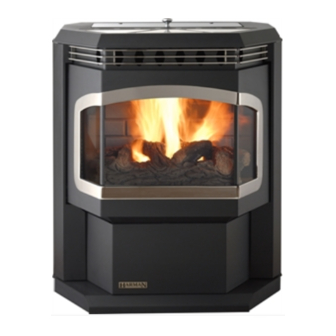
Advance Freestanding Pellet Stove
Advance
Use & Care Video
PlEASE rEAd ThIS ENTIrE mANuAl bEFOrE INSTAllATION ANd uSE OF ThIS PEllET FuEl-burNINg rOOm
hEATEr. FAIlurE TO FOllOw ThESE INSTruCTIONS COuld rESulT IN PrOPErTY dAmAgE, bOdIlY INjurY,
Or EvEN dEATh.
FOr uSE IN ThE u.S. ANd CANAdA. SuITAblE FOr INSTAllATION IN mObIlE hOmES
IF ThIS hArmAN
STOvE IS NOT PrOPErlY INSTAllEd, A hOuSE FIrE mAY rESulT. FOr YOur SAFETY, FOllOw
®
INSTAllATION dIrECTIONS.
CONTACT lOCAl buIldINg Or FIrE OFFICIAlS AbOuT rESTrICTIONS ANd INSTAllATION INSPECTION
rEQuIrEmENTS IN YOur ArEA.
CONTACT YOur lOCAl AuThOrITY (SuCh AS muNICIPAl buIldINg dEPArTmENT, FIrE dEPArTmENT, FIrE
PrEvENTION burEAu, ETC.) TO dETErmINE ThE NEEd FOr A PErmIT.
CETTE guIdE d'uTIlISATION EST dISPONIblE EN FrANCAIS. ChEz vOTrE CONCESSIONNAIrE dE hArmAN
hOmE hEATINg.
Installation & Operating manual
SAFETY NOTICE
SAvE ThESE INSTruCTIONS.
!
hOT SurFACES!
Glass and other surfaces are hot during
operation and cool down.
hot glass will cause burns.
• Do not touch glass until it is cooled
• NEVER allow children to touch glass
• Keep children away
• CAREFULLY SUPERVISE children in same room as
stove.
• Alert children and adults to hazards of high temperatures.
high temperatures may ignite clothing or other
flammable materials.
• Keep clothing, furniture, draperies and other flammable
materials away.
To obtain a French translation of this manual, please
contact your dealer or visit www.harmanstoves.com
Pour obtenir une traduction française de ce manuel, s'il
vous plaît contacter votre revendeur ou visitez www.
harmanstoves.com
Contact your local dealer with questions on installation,
operation or service.
WARNING
NOTE
1-90-09730R31_05/14
®
Advertisement
Table of Contents

Subscribe to Our Youtube Channel
Related Manuals for Harman Advance Freestanding Pellet Stove


Summary of Contents for Harman Advance Freestanding Pellet Stove
-
Page 1: Safety Notice
IN YOur ArEA. CONTACT YOur lOCAl AuThOrITY (SuCh AS muNICIPAl buIldINg dEPArTmENT, FIrE dEPArTmENT, FIrE PrEvENTION burEAu, ETC.) TO dETErmINE ThE NEEd FOr A PErmIT. CETTE guIdE d'uTIlISATION EST dISPONIblE EN FrANCAIS. ChEz vOTrE CONCESSIONNAIrE dE hArmAN ® hOmE hEATINg. -
Page 3: Table Of Contents
Introduction The Advance Pellet Stove This heating appliance does not just have automatic ignition, it has total automatic temperature control. The Advance uses a small room sensor rather than a wall thermostat for a more accurate temperature control. The Advance's control panel is designed for easy and efficient operation. It has 2 automatic modes of operation and 2 manual modes of operation. The Advance's specially designed burn pot and the "Advance Igniter" Automatic Ignition System, allow the unit to burn a large variety of biomass fuels with varying ash content. The Advance feed system has a maximum feed rate of 6 lbs. per hour and a minimum (maintenance) feed rate of 1.0 lbs. per hour. This 0 to 48,000 BTU pellet stove has an accordion style heat exchanger system that allows maximum surface area for the most efficient heat transfer in a smaller firebox. The unit has an easy to clean combustion system with an ash pan that holds ash from 1 ton of burned premium pellets. This unit is equipped with several different safety devices which will be explained later in this manual. 11.5” Model: Advance Modèle : Advance Serial No. Room Heater Pellet Fuel Burning BARCODE LABEL Appareil de chauffage à granulés de bois de série: Also for use In Mobile Homes. Utilisable dans mobile homes This this pellet burning appliance has been tested and listed for use In 1"... -
Page 4: Automatic Operation
Automatic Ignition/Operation The Advance pellet stove is more than just automatic ignition, it is also automatic temperature control. The automatic system will allow the fire size to be adjusted to match the heating needs and even put the fire out if necessary. If heat is needed after the fire is out, the Advance will automatically re-ignite and adjust the fire size to match the heating need. The totally automatic room sensor mode is recommended because of its efficiency. The unit can be switched between "AUTO" and "MANUAL" at any time during operation. Igniter switch to "AuTO" / room Temperature mode In "Room Temp Mode" heat output is controlled automatically by the Room Sensing Probe. When the Room Sensing Probe calls for heat, the stove will increase output. When the Room Sensing Probe is getting close to the set temperature, the stove will begin to level off output and keep the fire burning at just the right temperature to maintain that setting. High output is determined by the feed rate setting. This setting, generally on #4, can be increased if higher burn rates are necessary. The unit's maximum burn rate should not create less than 1" of ash on the burn pot front edge. See... - Page 5 Automatic Start up Starting First Fire Igniter Switch to "AuTO" (up position) Make sure the unit is plugged into a 120 VAC, 60 HZ electrical source. The power light should be the only light lit. To avoid unwanted smoke, be sure there is no fuel or See Hint #7. combustibles in the ash pan prior to lighting. Flame Guide 1" Fig. 1 1. Turn mode Selector to "OFF".
-
Page 6: Manual Operation
manual Ignition/Operation The Advance Pellet Stove is capable of manual operation. This also allows the operator to manually control operation during an emergency (i.e. igniter failure.) The unit can be switched between "AUTO" and "MANUAL" at any time during operation. NOTE: It is possible to start a fire in "Auto" and switch to "manual" at any time. Once an ignition cycle begins, it will continue, regardless of mode. room Temperature mode / Igniter switch to "mANuAl"... - Page 7 manual Start up Starting First Fire / Igniter Switch to "mANuAl" Make sure the unit is plugged into a 120 VAC, 60 HZ electrical source. The power light should be the only light lit. To avoid unwanted smoke, be sure there is no fuel or combustibles in the ash pan prior to lighting. Fig. 4 1. Turn FEEd AdjuSTEr to desired feed rate. #4 is good for most pellets.
-
Page 8: Esp Control
Room Temp Mode, using the outer scale marked in only. Requires special DDM Room Temp Mode, Constant Burn degrees Fahrenheit. It also allows you to adjust the monitor supplied to Harman Mode, or OFF. Also allows you to ® constant burn setting, while in Constant Burn Mode, Dealers exclusively. -
Page 9: Assembly & Installation
Installation Alternate floor protector Consult with your local building code agency and insurance 7" / 178mm dimension may be used representative before you begin your installation to ensure as long as they satisfy the compliance with local codes, including the need for permits measurement requirements and follow-up inspections. shown below. Minumum size floor protection Several issues must be addressed when selecting a suitable for a corner installation hearth... - Page 10 removing Side doors for Installation removing Side doors Figure 9 Use hand hole to swing open side doors to at least 90°. Figure 10 Remove side doors by lifting upward on the door until the Hand Hole bottom pin is out of its hole. Move the bottom of the door out and away from the pedestal base about 1/2". Allow the door to slide downward until the top door pin is out of its top hole. NOTE: Always remove the side doors and rear shields to Side Door move the unit. This will keep them from getting damaged. removing the rear motor Shield Sheet metal. Fig. 9 NOTE: Disconnect power to the unit before removing the motor shields. Danger of electrical shock. Hot and moving parts could cause injury.
-
Page 11: Low Draft Voltage Adjustment
low draft voltage Adjustment C o m b u s t i o n M o t o r S p e e d Control Low draft only set point. Draft Meter bolt The small straight hole location screwdriver slot is plastic; therefore, the unit can be adjusted while in operation. - Page 12 room Sensor and Air grill Installation room Sensor Installation Air grill Installation The room sensor is a small temperature sensor on the end Insert the two tail end hooks of the Air Grill Assembly up of a 60" gray or black wire. This sensor is installed much under the stove top edge. Insert inward until the two center like a standard wall thermostat. Because it is so small, it hooks drop into the stove body slots in the front of the unit. can be hidden along the trim of a doorway or even up the leg of a coffee table. There is a remote room sensor port on the rear of the unit for easy external connection. Use standard 18-2 thermostat wire to extend the distance to the desired location (50' maximum). The room sensor should be installed in the location where you want to control the temperature. NOTE: Distances of more than 25 feet from the unit or in another room are not recommended. It is recommended that the room sensor be installed, even if only installed on the rear of the unit as a return air sensor. The room sensor is essential for the Advance's excellent efficiency. Center Hooks Tail End Hooks Fig. 17 Room Sensor Outlet rEmINdErS Do not allow pellets or sawdust to build up on the hopper lid gasket. Inspect the hopper lid gasket for damage. A good hopper lid seal is very important for proper operation.
-
Page 13: Venting
NOTE: Simpson duravent Pelletvent Pro harman ® and located lower on the wall than the exhaust vent outlet. Adapter Part #3PvP-Adhb and Pelletvent Pro harman ® Adapter Increaser Part #3PvP-x4Adhb are highly When the appliance is roof vented: The air intake is best recommended to be installed on the starter collar to located on the exterior wall oriented towards the prevailing insure a proper pipe connection to the unit. - Page 14 Pass-through connecting the flex pipe. The pipe should be run outside and The harman direct vent wall Pass-through (Part # 1-00- ® terminate to the side or below the vent pipe outlet so the flue 677177) makes installing your harman Pellet Stove with ® outlet is more than 12" from the inlet cover. Inlet cover part outside air much easier. It is made to fit walls from 4 1/2" up number 1-10-09542 should be used to keep birds, rodents, to 10 1/8"...
- Page 15 venting #1 Preferred method This method provides excellent venting for normal operation and allows the stove to be installed closest to the wall. One inch from the wall is safe; however, two or three inches allows better access to remove the rear panel. The vertical portion of the vent should be three to five feet high. This vertical section will provide natural draft in the event of a power failure. 3 Ft. Combustibles 3 Ft. to Combustibles Fig. 20 #2 Preferred method This method also provides excellent venting for normal operation but requires the stove to be installed farther from the wall. The vertical portion of the vent should be three to five feet high and at least three inches from a combustible wall. This vertical section will provide natural draft in the event of a power failure. CAUTION KEEP COmbuSTIblES (SuCh AS grASS, lEAvES, 3 Ft.
- Page 16 venting #3 Installing into an existing chimney This method can be used for normal operation. This method also provides natural draft in the event of a power failure. If the chimney condition is questionable you may want to install a liner as in method #6. ThE ChImNEY muST bE OF A TYPE SuITAblE FOr SOlId-FuEl burNINg. WARNING ThE ChImNEY ANd CONNECTOr muST bE mAINTAINEd IN gOOd CONdITION ANd KEPT ClEAN. Fig. 22 #4 Installing into an existing fireplace chimney This method can be used for normal operation. This method also provides natural draft in the event of a power failure.
- Page 17 venting #5 Installing into an existing fireplace chimney This method provides excellent venting for normal operation. This method also provides natural draft in the event of a power failure. In Canada and some places in the US it is required that the vent pipe extend all the way to the top of the chimney. In this method a cap should also be installed on the chimney to keep out rain. Be sure to use approved pellet vent pipe fittings. Seal pipe joints with silicone in addition to the sealing system used by the manufacturer. Pipe size should be increased to 4" using this method. ThE ChImNEY muST bE OF A TYPE SuITAblE FOr SOlId-FuEl burNINg.
- Page 18 venting #7 Installing through the ceiling vent Minimum flue vent configuration Through the ceiling vent, follow PL vent manufacturer's It is recommended that outside air be installed with this recommendations when using wall and ceiling pass through. venting configuration. storm collar ashing 1" MIN. 1" MIN. 1" MIN. No insulation or other PL vent manufacturer's combustible materials...
- Page 19 venting Inside Corner Detail Fixed Porch or Deck Closed Openable Openable or Fixed Fixed Closed Openable Sidewalk =Vent Terminal =Air Supply Inlet =Area where termination is not permitted requirements for Terminating the venting I. The clearance to service regulator vent outlet must be a minimum of 6 feet. WARNING: Venting terminals must not be recessed into a wall or siding. J. The clearance to a non-mechanical air supply inlet to the building or the combustion air inlet to any other appliance NOTE: Only "pellet" vent pipe wall pass-throughs and fire must be a minimum of 48”.
- Page 20 Safety Information dO NOT INSTAll A FluE dAmPEr IN ThE ExhAuST WARNING vENTINg SYSTEm OF ThIS uNIT. dO NOT CONNECT ThIS uNIT TO A ChImNEY FluE mObIlE hOmE rEgulATIONS dO NOT AllOw SErvINg ANOThEr APPlIANCE. INSTAllATION IN A rOOm dESIgNATEd FOr SlEEPINg.
-
Page 21: Maintenance
maintenance - Emptying Ashes Ash Pan removal and re-attachment CAuTION: Surfaces are hot while in operation, wear gloves to protect from burns. 1. Open side doors. Fig. 29 2. Release spring latches on the right and left side of the ash pan. Fig. 30 3. Slide ash pan forward enough to lift with center handle. Empty ashes and reinstall ash pan. Fig. 31 disposal of Ashes: Ashes should be placed in a steel container with a tight fitting lid. - Page 22 To remove the view door from the stove, hold the door by the bottom and lift upward, off of the hinge pins. See Fig. 33 The glass in your Harman stove is a special ceramic glass. ® dO NOT abuse the glass by striking or slamming shut. Fig. 33 Never burn the appliance if the door glass is cracked or broken. replace only with Harman supplied 5mm ceramic glass. ® Door Assembly wArNINg - Do NOT Use Substitute Materials. Clean the glass with a soft cloth and mild glass cleaner. Do Top Glass Clip not clean the glass when hot, and avoid the use of abrasive cleaners. Side Glass Clip...
- Page 23 maintenance - burn Pot burn Pot Cleaning and maintenance 1. Scrape the top holed surface and sides of the burn pot. Fig. 35. It is not necessary to completely remove all material from the burn pot. The excess will be pushed out during the next use. 2. Loosen the (2) wing thumb screws on the lower front angle of the burn pot. Fig. 36 3. Lift off the clean-out cover to open the bottom clean-out chamber. Fig. 37 dANGeR Fig. 35 disconnect the power to the unit before removing cover. 4. Clean ash buildup from inside the chamber while cover is off. Use the scraper to tap on the top front edge of the burn pot. This will help knock pieces of ash, loosened by the scraping process, down through the holes. It also helps knock scale off of the igniter element.
- Page 24 maintenance - Flame guide and brick Panel removing Flame guide and brick Panel Slide brick panel straight upward with both hands. While holding the brick panel up with one hand, remove the flame guide from the top of the burn pot. Fig. 38 Slide the brick panel into the left corner of the firebox with the panel resting on the top edges of the burn pot. Rotate the right side of the brick panel through the door opening. Fig. 39 Reverse this operation to reinstall the brick panel after cleaning. Flame Guide/Brick panel holder Firebox Brick Burn pot Panel...
- Page 25 maintenance - Combustion Intake Cover Cleaning and maintenance for the Combustion Intake Cover Retainer Handle Cover You will need to remove the combustion intake cover, behind the ash pan, to clean the fan blades and rear flue tube. Rotate the retainer cover handle counter-clockwise upward as far as it will go (approximately 90°). Fig. 40 Hold the combustion intake cover handle and pull until the side of the cover at the retainer handle end comes away from the stove body, approximately 15-20°, slide the right side tab out of the retaining slot. Fig. 41 Clean and inspect the fully exposed combustion fan blade and flue tube. Fig. 42 Combustion Intake Cover Reinstall the combustion intake cover by first sliding the right side tab into the retainer slot. Rotate the cover inward until the cover fits into its hole. Make sure the two faces of the cover and retainer are seated properly then rotate the retainer handle clockwise until it stops. Fig. 41 CAUTION Excessive cleaning force could bend the small...
- Page 26 Maintenance - Heat Exchanger Cleaning the Heat Exchanger System 1. Remove brick panel and flame guide. Fig. 38 & 39. 2. Remove the ash pan. Fig. 31. 3. Remove flue baffles located on each side of the burnpot. Fig. 43 & 44. The baffle is held in place by inserting the tab into the slot (located toward the outside of the firebox) and resting on the hook tab located beside the burnpot. 4. Pull the pointed end of the baffle slightly front with one hand while pushing up from below with the other hand. Fig. 44. 5. With the baffle released from the tabs, rotate the pointed Hook Tab Slot end toward the door opening. Lift baffle up and out. Fig.43 The right and left baffle are interchangeable. 6. Now remove the heat exchanger baffle plates. Fig. 45. To remove the left plate, slide the center lock to the right. To remove the right plate, slide the center lock to the left. (The right and left plates are interchangeable.) This will allow access to all of the rear vertical heat exchanger surfaces. 7. With all four baffle plates removed, cleaning can be performed with the arrow end of the scraper. Fig. 46.
- Page 27 motor & Component locations Low Draft Pressure Switch Feed motor backdraft damper Assembly Always check to see if the damper Combustion Blower plate swings freely inward and that the seating edges are not covered with dirt or lint. Advance Pellet Stove Safety devices The Control board/ESP combination is responsible for all high The low draft Pressure Switch is a differential pressure switch limit safety control. There are 2 high limits, one normal operation...
-
Page 28: Troubleshooting
Trouble-Shooting STOvE dOES NOT FEEd SmOKE IS vISIblE COmINg OuT OF vENT 1. No fuel in hopper. 1. Air-fuel ratio is too rich. 2. Firebox draft may be too low for sensing switch in feeder a. Feed rate too high. circuit to operate. Check for closed doors, loose or b. Draft too low caused by a gasket leak. missing gasket on doors or hopper lid. lOw hEAT OuTPuT 3. Feed motor will not run until the ESP control senses a 1. Feed rate too low certain temperature. Maybe you did not put enough fuel 2. Draft too low because of gasket leak. or starting gel in the burn pot before manually lighting 3. Poor quality or damp pellets the fire. 4. Combination of 1 and 2. 4. Restriction in the hopper or feeder. Remove all fuel and examine. Clear the obstruction. helpful hints 5. Feed motor has failed. - Page 29 Fuel Specifications Fuel and Fuel Storage Size Pellet fuel quality can fluctuate from manufacturer to • Pellets are either 1/4 inch or 5/16 inch (6-8mm) in manufacturer, and even from bag to bag. diameter Hearth & Home Technologies recommends using only fuel • Length should be no more than 1-1/2 inches (38mm) that is certified by the Pellet Fuels Institute (PFI). • Pellet length can vary from lot to lot from the same manufacturer Fuel Material •...
-
Page 30: Specifications
Specifications 20 3/4” 26 5/8” 7 9/16” 5 5/16” weight 250 lbs. blower 135 cfm hopper Capacity 60 lbs. Fuel Wood Pellets or Corn/Pellet Mix Outside Air Size 3 inches Fuse rating 6 amp bTu range 0 to 48,000 Feed rate 1.0 lbs./hr. -
Page 31: Wiring Diagram
Advance wiring diagram 1-90-09730R31_05/14... - Page 32 hearth & home Technologies lImITEd lIFETImE wArrANTY Hearth & Home Technologies, on behalf of its hearth brands (”HHT”), extends the following warranty for HHT gas, wood, pellet, coal and electric hearth appliances that are purchased from an HHT authorized dealer. wArrANTY COvErAgE: HHT warrants to the original owner of the HHT appliance at the site of installation, and to any transferee taking ownership of the appliance at the site of installation within two years following the date of original purchase, that the HHT appliance will be free from defects in materials and workmanship at the time of manufacture. After installation, if covered compo- nents manufactured by HHT are found to be defective in materials or workmanship during the applicable warranty period, HHT will, at its option, repair or replace the covered components. HHT, at its own discretion, may fully discharge all of its obligations under such warranties by replacing the product itself or refunding the verified purchase price of the product itself. The maximum amount recoverable under this warranty is limited to the purchase price of the product. This warranty is subject to conditions, exclusions and limitations as described below. wArrANTY PErIOd: Warranty coverage begins on the date of original purchase. In the case of new home construction, warranty coverage begins on the date of first occupancy of the dwelling or six months after the sale of the product by an independent, authorized HHT dealer/ distributor, whichever occurs earlier. The warranty shall commence no later than 24 months following the date of product shipment from HHT, regardless of the installation or occupancy date. The warranty period for parts and labor for covered components is produced in the following table. The term “Limited Lifetime” in the table below is defined as: 20 years from the beginning date of warranty coverage for gas appliances, and 10 years from the beginning date of warranty coverage for wood, pellet, and coal appliances. These time periods reflect the minimum expected useful lives of the designated components under normal operating conditions. Warranty Period HHT Manufactured Appliances and Venting Components Covered Parts Labor Wood Pellet Coal Electric Venting Wood All parts and material except as covered by Conditions, 1 Year...
-
Page 33: Warranty Conditions
wArrANTY CONdITIONS: • This warranty only covers HHT appliances that are purchased through an HHT authorized dealer or distributor. A list of HHT authorized dealers is available on the HHT branded websites. • This warranty is only valid while the HHT appliance remains at the site of original installation. • This warranty is only valid in the country in which the HHT authorized dealer or distributor that sold the appliance resides. • Contact your installing dealer for warranty service. If the installing dealer is unable to provide necessary parts, contact the nearest HHT authorized dealer or supplier. Additional service fees may apply if you are seeking warranty service from a dealer other than the dealer from whom you originally purchased the product. • Check with your dealer in advance for any costs to you when arranging a warranty call. Travel and shipping charges for parts are not covered by this warranty. wArrANTY ExCluSIONS: This warranty does not cover the following: • Changes in surface finishes as a result of normal use. As a heating appliance, some changes in color of interior and exterior surface finishes may occur. This is not a flaw and is not covered under warranty. • Damage to printed, plated, or enameled surfaces caused by fingerprints, accidents, misuse, scratches, melted items, or other external sources and residues left on the plated surfaces from the use of abrasive cleaners or polishes. • Repair or replacement of parts that are subject to normal wear and tear during the warranty period. These parts include: paint, wood, pellet and coal gaskets, firebricks, grates, flame guides, batteries and the discoloration of glass. • Minor expansion, contraction, or movement of certain parts causing noise. These conditions are normal and com- plaints related to this noise are not covered by this warranty. • Damages resulting from: (1) failure to install, operate, or maintain the appliance in accordance with the installation instructions, operating instructions, and listing agent identification label furnished with the appliance; (2) failure to install the appliance in accordance with local building codes; (3) shipping or improper handling; (4) improper opera- tion, abuse, misuse, continued operation with damaged, corroded or failed components, accident, or improperly/ incorrectly performed repairs; (5) environmental conditions, inadequate ventilation, negative pressure, or drafting caused by tightly sealed constructions, insufficient make-up air supply, or handling devices such as exhaust fans or forced air furnaces or other such causes; (6) use of fuels other than those specified in the operating instructions; (7) installation or use of components not supplied with the appliance or any other components not expressly authorized and approved by HHT; (8) modification of the appliance not expressly authorized and approved by HHT in writing;... -
Page 34: Service Parts List
Advance Service Parts Pellet Stove beginning manufacturing date: N/A 1-70-08730-1 (black) Ending manufacturing date: Active retired units 1-70-08730-5 (Honey Glo) (Ending Manufacturing Date: June 2009) 1-70-08730-2 (Charcoal) Ending Manufacturing Date: June 2009) 1-70-08730-7 (Black) (Ending Manufacturing Date: June 2009) 1-70-08730-3 (Goldenfi re) (Ending Manufacturing Date: June 2009) 1-70-08730-10 (Mojave Red) (Ending Manufacturing Date Jan 2010) 1-70-08730-4 (Metallic Blue) (Ending Manufacturing Date Jan 2010) 1-70-08730-12 (Forest Green) (Ending Manufacturing Date Jan 2010 IMPORTANT: THIS IS DATED INFORMATION . Parts must be ordered from a dealer or Stocked hearth and home Technologies does not sell directly to consumers distributor. - Page 35 Advance Service Parts beginning manufacturing date: N/A Ending manufacturing date: Active #3 hopper lid Assembly IMPORTANT: THIS IS DATED INFORMATION . Parts must be ordered from a dealer or Stocked hearth and home Technologies does not sell directly to consumers distributor.
- Page 36 Advance Service Parts beginning manufacturing date: N/A Ending manufacturing date: Active IMPORTANT: THIS IS DATED INFORMATION . Parts must be ordered from a dealer or Stocked hearth and home Technologies does not sell directly to consumers distributor. . Provide model number and serial number when requesting service parts from your dealer or distributor. at depot ITEm description COmmENTS...
- Page 37 Advance Service Parts beginning manufacturing date: N/A Ending manufacturing date: Active Pre Serial Number 008360001 24.1 Feeder Assembly 24.2 24.17 24.3 24.4 24.16 24.15 24.14 24.13 24.8 24.6 24.5 24.10 24.7 24.9 24.12 IMPORTANT: THIS IS DATED INFORMATION . Parts must be ordered from a dealer or Stocked hearth and home Technologies does not sell directly to consumers distributor.
- Page 38 Advance Service Parts beginning manufacturing date: N/A Ending manufacturing date: Active Post Serial Number 008360001 Feeder Assembly 25.14 25.15 25.11 25.13 25.12 25.1 25.2 25.10 25.9 25.3 25.8 25.4 25.5 25.7 25.6 IMPORTANT: THIS IS DATED INFORMATION . Parts must be ordered from a dealer or Stocked hearth and home Technologies does not sell directly to consumers distributor.
- Page 39 Advance Service Parts beginning manufacturing date: N/A Ending manufacturing date: Active #26 hardware Kit 26.1 26.2 26.3 26.6 26.5 26.4 IMPORTANT: THIS IS DATED INFORMATION . Parts must be ordered from a dealer or hearth and home Technologies does not sell directly to consumers distributor.
- Page 40 DDM Replacement Cable 1-00-05402 Diagnostic Display Meter 3-20-05401 Disconnect, Female, 1/4" Pkg fo 25 1-00-00959 Disconnect, Male, 1/4" Pkg of 25 1-00-00957 Door Hinge Weldment Qty 2 req 1-10-08735W Draft Meter Assembly 1-00-00637 Draft Meter Bolt & Tube 1-00-04004 Flue Brush 3-40-06663 Harman Gold Label Pkg of 5 3-90-08540-5 Harman Silver Label Pkg of 5 3-90-04580-5 Hopper Muffl er and Fitting 1 Set 1-00-18186618 Labels, Caution & Danger 10 Each 1-00-200408541 Labels, Control Board 3-90-06655A Labels, Large Caution 3-90-00247 Magnet & Hardware Pkg of 4 1-00-08569...
-
Page 41: Corn Addendum
Addendum for Burning Corn and Pellet Fuel Mixture Harman® pellet burning, free-standing stoves and inserts have been tested to ASTM E1509 for burning shelled corn in a mixture with wood pellets. The listing approves up to a 50% corn and 50% pellet mixture. Different mixtures of corn will have distinctively different burn characteristics depending upon moisture content and variety. -
Page 42: Power Failures
Contact your dealer if you have questions about UPS compatibility with your appliance. Harman® Surefire 512H Battery Back-up The 512H connects to a 12 volt deep cycle battery that will run your appliance for up to eight (8) hours. It includes a trickle charge feature that keeps your battery charged when power is available. - Page 43 Service & maintenance log Date Of Service Performed By Description Of Service 1-90-09730R31_05/14...
- Page 44 (Signature of Boxer) Your premium quality hearth product designed and assembled by the experienced and skilled members at Harman in Halifax, ® PA, USA. Proudly Printed On 100% Recycled Paper...
Need help?
Do you have a question about the Advance Freestanding Pellet Stove and is the answer not in the manual?
Questions and answers