HP P2000 G3 User Manual
Sas msa system
Hide thumbs
Also See for P2000 G3:
- Cli reference manual (532 pages) ,
- Reference manual (148 pages) ,
- Specification (43 pages)

Related Manuals for HP P2000 G3


Summary of Contents for HP P2000 G3
- Page 1 HP P2000 G3 SAS MSA System User Guide Part number: 614561-002 First edition: July 201 1...
- Page 2 Legal and notice information © Copyright 201 1 Hewlett-Packard Development Company, L.P. Confidential computer software. Valid license from HP required for possession, use or copying. Consistent with FAR 12.21 1 and 12.212, Commercial Computer Software, Computer Software Documentation, and Technical Data for Commercial Items are licensed to the U.S. Government under vendor's standard commercial license.
-
Page 3: Table Of Contents
P2000 G3 SAS MSA System controller module face plate ....... . - Page 4 Connecting the enclosure to data hosts ..........37 SAS host ports.
- Page 5 Rear panel LEDs ..............59 P2000 G3 SAS MSA System SFF and P2000 G3 SAS MSA System LFF..... . . 59 D2700 6Gb drive enclosure .
- Page 6 Contents...
- Page 7 Figures 1 P2000 G3 MSA System component connection combinations ......25 2 Cabling connections between P2000 G3 MSA System controllers and P2000 6Gb drive enclosures . . 28 3 Cabling connections between P2000 G3 controllers and D2700 6Gb drive enclosures .
- Page 8 Figures...
- Page 9 17 LEDs — HP MSA2000 3Gb rear panel ..........62 18 LEDs — HP P2000 G3 MSA System power supply units — rear panel ......63 19 Rackmount enclosure dimensions .
- Page 10 Tables...
-
Page 11: About This Guide
About this guide This guide provides information about hardware setup for the HP P2000 G3 SAS MSA System controller enclosures. Intended audience This guide is intended for storage system administrators. Prerequisites Prerequisites for installing and using this product include knowledge of: •... -
Page 12: Document Conventions And Symbols
Document conventions and symbols Table 1 Document conventions Convention Element Medium blue text: Figure 1 Cross-reference links and e-mail addresses Medium blue, underlined text Web site addresses http://www.hp.com Bold font • Key names • Text typed into a GUI element, such as into a box •... -
Page 13: Rack Stability
• After signing up, you can quickly locate your products by selecting Business support and then Storage under Product Category. HP P2000 G3 SAS MSA System User Guide... -
Page 14: Hp Websites
HP websites For additional information, see the following HP websites: • http://www.hp.com • http://www.hp.com/go/storage • http://www.hp.com/service_locator • http://www.hp.com/support/manuals • http://www.hp.com/support/downloads • http://www.hp.com/storage/whitepapers • http://www.hp.com/go/p2000 Documentation feedback HP welcomes your feedback. To make comments and suggestions about product documentation, please send a message to storagedocs.feedback@hp.com. -
Page 15: Overview
Overview The HP P2000 G3 SAS MSA System is a high-performance storage solution combining outstanding performance with high reliability, availability, flexibility, and manageability. Features and benefits Product features and supported options are subject to change. Online documentation describes the latest product and product family characteristics, including currently supported features, options, technical specifications, configuration data, related optional software, and product warranty information. - Page 16 Overview...
-
Page 17: Components
Fault ID LED P2000 G3 SAS MSA System SFF Right ear Left ear P2000 Enclosure ID LED Unit Identification (UID) LED Disk drive Online/Activity LED Heartbeat LED Disk drive Fault/UID LED Fault ID LED HP P2000 G3 SAS MSA System User Guide... -
Page 18: Disk Drive Bay Numbers
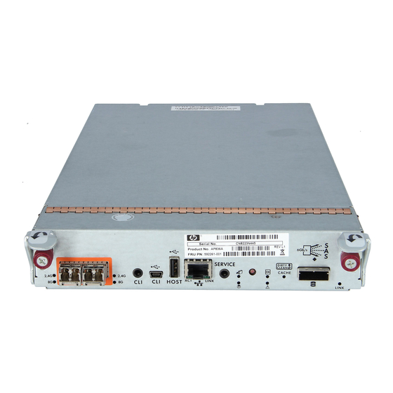
P2000 Rear panel view — controller module The P2000 G3 MSA System controller module shown below is not proportionately sized relative to preceding controller enclosure views. The controller module face plate is enlarged to show relevant detail. P2000 G3 SAS MSA System controller module face plate... -
Page 19: Rear Panel Components
Drive enclosures attach to the controller enclosure for the purpose of expanding storage capacity. Drive enclosures supported by the P2000 G3 MSA System controllers are described in the following sections. The 3Gb drive enclosures supported by the newer controller enclosures are listed for customers upgrading existing legacy systems. -
Page 20: P2000 6Gb 3.5" 12-Drive Enclosure
Service port (used by service personnel only) MSA70 3Gb drive enclosure P2000 G3 MSA System controllers can also be attached to an MSA70 3Gb drive enclosure that is running firmware version 2.18 or later. For information about the MSA70 3Gb drive enclosure, see the HP... -
Page 21: Transportable Compactflash
Super-capacitor pack To protect RAID controller cache in case of power failure, P2000 G3 MSA System controllers are equipped with super-capacitor technology, in conjunction with CompactFlash memory, built into each controller module to provide unlimited cache memory backup time. The super-capacitor pack provides energy for backing up unwritten data in the write cache to the CompactFlash in the event of a power failure. - Page 22 Components...
-
Page 23: Installing The Enclosures
6Gb P2000 G3 MSA System drive enclosures when expanding storage capacity. P2000 G3 MSA System controller to drive enclosure cabling is described within this chapter. Cabling of 3Gb drive enclosures to newer 6Gb controllers is addressed for customers upgrading existing legacy systems. -
Page 24: Connecting Controller And Drive Enclosures
A P2000 6Gb 3.5" 12-drive enclosure, supporting 6Gb internal disk drive and expander link speeds, can be attached to a P2000 G3 SAS MSA System LFF or P2000 G3 SAS MSA System SFF controller enclosure using supported mini-SAS to mini-SAS cables of 0.5m to 2m length (see Figure 2 on page 28). -
Page 25: Connecting Controller And Mixed Drive Enclosures
Connecting controller and mixed drive enclosures P2000 G3 MSA System controller modules support cabling of 3Gb and 6Gb SAS link-rate LFF and SFF expansion modules — in mixed fashion — as shown in Figure 10 on page 32, and as further described Additional cabling considerations (below);... -
Page 26: Additional Cabling Considerations
IMPORTANT: Controller modules within the enclosure must be of the same type. Do not install an HP P2000 G3 FC MSA System and HP P2000 G3 SAS MSA System controller module in the same chassis. IMPORTANT: Connecting 3Gb and 6Gb drive enclosures limits performance and should be done only when upgrading legacy product configurations. -
Page 27: Sas Expansion Cable Requirements: Expansion Module To Expansion Module Connection
When adding more than two drive enclosures, you may need to purchase additional 1m or 2m cables: • Spanning 3, 4, or 5 drive enclosures requires 1m cables. • Spanning 6 or 7 drive enclosures requires 2m cables. HP P2000 G3 SAS MSA System User Guide... -
Page 28: Cabling Connections Between P2000 G3 Msa System Controllers And P2000 6Gb Drive Enclosures
Controller A Controller B Figure 2 Cabling connections between P2000 G3 MSA System controllers and P2000 6Gb drive enclosures Figures 2 - 4 show a single controller module connected to a single expansion module (illustrations on left), with dual controller modules connected to dual expansion modules (illustrations on right). -
Page 29: Cabling Connections Between P2000 G3 Controllers And An Msa70 3Gb Drive Enclosure
Controller A Controller B In Out In Out Figure 5 Cabling connections between P2000 G3 controllers and an MSA70 3Gb drive enclosure The diagram above shows dual-controller modules connected to dual-expansion modules. Controller A Controller B Figure 6 Fault-tolerant cabling: P2000 G3 controllers and P2000 6Gb drive enclosures The diagram above shows a dual-controller enclosure cabled to P2000 6Gb drive enclosures featuring dual-expansion modules. -
Page 30: Cabling Connections Between P2000 G3 Controllers And D2700 6Gb Drive Enclosures
Figure 7 Cabling connections between P2000 G3 controllers and D2700 6Gb drive enclosures The figure above provides sample diagrams reflecting cabling of P2000 G3 controller enclosures and D2700 6Gb drive enclosures. The diagram at left shows a dual-controller enclosure cabled to D2700 6Gb drive enclosures featuring dual-expansion modules. -
Page 31: Fault-Tolerant Cabling: P2000 G3 Controllers And Msa2000 3Gb Drive Enclosures
Controller A Controller B Figure 8 Fault-tolerant cabling: P2000 G3 controllers and MSA2000 3Gb drive enclosures Controller A Controller B In Out In Out In Out In Out In Out In Out Figure 9 Fault-tolerant cabling: P2000 G3 controllers and MSA70 3Gb drive enclosures... -
Page 32: Cabling Connections Between Dual Controllers And Drive Enclosures Of Mixed Type
Although 6Gb drive enclosures can be cabled after an MSA70 3Gb drive enclosure, performance of the 6Gb devices will be limited to 3Gb. IMPORTANT: For comprehensive configuration options and associated illustrations, refer to the HP P2000 G3 MSA System Cable Configuration Guide. Installing the enclosures... -
Page 33: Testing Enclosure Connections
Connect the cables and power cords to the enclosures as explained in the installation sheet. • NOTE: P2000 G3 controller enclosures and some P2000 G3 drive enclosures do not have power switches. They power on when connected to a power source, and they power off when disconnected. •... -
Page 34: Power Cords
Stop all I/O from hosts to the system. Shut down both controllers using either method described below: • Use SMU to shut down both controllers, as described in the online help and web-posted HP P2000 G3 MSA System SMU Reference Guide. Proceed to step •... -
Page 35: Dc Model
Stop all I/O from hosts to the system. Shut down both controllers using either method described below: • Use SMU to shut down both controllers, as described in the online help and HP P2000 G3 MSA System SMU Reference Guide. - Page 36 Installing the enclosures...
-
Page 37: Connecting Hosts
512 LUNs per P2000 G3 storage system (single or dual controller configuration). SAS host ports The P2000 G3 SAS MSA System controller modules use the Serial Attached SCSI (Small Computer System Interface) interface protocol for host port connection, featuring either one or two controller modules. Each... -
Page 38: Connecting Direct Attach Configurations
To connect the P2000 G3 SAS MSA System controller to a server or HBA switch — using the controller’s SAS host ports — select SAS cables supporting 3/6Gb data rates that are compatible with the controller module’s host port SFF connector. -
Page 39: Four Servers/One Hba Per Server/Dual Path
Connecting remote management hosts The management host directly manages systems out-of-band over an Ethernet network. Connect an RJ-45 Ethernet cable to the network management port on each P2000 G3 MSA System controller. Connect the other end of each Ethernet cable to a network that your management host can access (preferably on the same subnet). - Page 40 Connecting hosts...
-
Page 41: Connecting To The Controller Cli Port
Connecting to the controller CLI port Device description P2000 G3 MSA System controllers feature a new command-line interface (CLI) port used to cable directly to the controller and initially set IP addresses, or perform other configuration tasks. This port differs from G1 and G2 controllers. -
Page 42: Setting Network Port Ip Addresses Using Dhcp
Insert the P2000 G3 Software Support/Documentation CD into the CD drive on a Linux or Windows computer on the network that is connected to your controller enclosure. Use Autorun or manually start the CD. The MSA Device Discovery Tool will run. -
Page 43: Terminal Emulator Display Settings
Enter the default password !manage. If the default user or password — or both — have been changed for security reasons, enter the secure login credentials instead of the defaults shown above. HP P2000 G3 SAS MSA System User Guide... - Page 44 At the prompt, type the following command to set the values you obtained in Step 1 for each network port, first for controller A and then for controller B: address netmask gateway set network-parameters ip netmask gateway controller a|b where: •...
-
Page 45: Basic Operation
IMPORTANT: For detailed information on accessing and using SMU, see the “Getting started” section in the web-posted HP P2000 G3 MSA System SMU Reference Guide. The Getting Started section provides instructions for signing-in to SMU, introduces key concepts, addresses browser setup, and provides tips for using the main window and the help window. - Page 46 Basic operation...
-
Page 47: Troubleshooting
Troubleshooting CLI port connection P2000 G3 MSA System controllers feature a new CLI port employing a mini-USB Type B form factor. If you encounter problems communicating with the port after cabling your computer to the USB device, you may need to either download a device driver (Windows), or set appropriate parameters via an operating system command (Linux). -
Page 48: If The Enclosure Does Not Initialize
If the enclosure does not initialize It may take up to two minutes for the enclosures to initialize. If the enclosure does not initialize: • Perform a rescan. • Power cycle the system. • Make sure the power cord is properly connected, and check the power source that it is connected to. •... -
Page 49: Is The Controller Back Panel Ok Led Off
Check the event log for specific information Online/Activity predictive failure alert may have been regarding the fault. LED is blinking. received for this device. • Isolate the fault. • Contact an authorized service provider for assistance. HP P2000 G3 SAS MSA System User Guide... -
Page 50: Is A Connected Host Port's Host Link Status Led Off
Is a connected host port’s Host Link Status LED off? Answer Possible reasons Actions System functioning properly. No action required. (see Link LED note: page 60) The link is down. • Check cable connections and reseat if necessary. • Inspect cables for damage. •... -
Page 51: Is The Power Supply's Input Power Source Led Off
Transportable cache only applies to single-controller configurations. In dual controller configurations, there is no need to transport a failed controller’s cache to a replacement controller because the cache is duplicated between the peer controllers. HP P2000 G3 SAS MSA System User Guide... -
Page 52: If The Controller Has Failed Or Does Not Start, Is The Cache Status Led On/Blinking
To preserve the existing data stored in the CompactFlash, you must transport the CompactFlash from the failed controller to a replacement controller using a procedure outlined in the HP P2000 G3 MSA System controller replacement instructions, shipped with the replacement controller. Failure to use this procedure will result in the loss of data stored in the cache module. -
Page 53: Isolating A Controller Module Expansion Port Connection Fault
Is the expansion port status LED on? • Yes – You have isolated the problem to the drive enclosure’s port. Replace the expansion module. • No – Proceed to the next step. HP P2000 G3 SAS MSA System User Guide... -
Page 54: Resolving Voltage And Temperature Warnings
Replace the cable with a known good cable, ensuring the cable is attached to the original ports used by the previous cable. Is the host link status LED on? • Yes – Replace the original cable. The fault has been isolated. •... -
Page 55: Temperature Sensors
Sensor Event/Fault LED condition Power supply 1 voltage, 12V < 1 1.00V > 13.00V Power supply 1 voltage, 5V < 4.00V > 6.00V Power supply 1 voltage, 3.3V < 3.00V > 3.80V HP P2000 G3 SAS MSA System User Guide... - Page 56 Troubleshooting...
-
Page 57: Aled Descriptions
7 10 9 12 Left ear Right ear P2000 Table 12 LEDs — HP P2000 G3 MSA Systems controller enclosure front panels Description Definition Enclosure ID Green — On Enables you to correlate the enclosure with logical views presented by management software. Sequential enclosure ID numbering of controller enclosures begins with the integer 1. -
Page 58: Disk Drive Leds
Disk drive LEDs 3.5" LFF disk drive 2.5" SFF disk drive Table 13 LEDs — Disk drive LEDs Description Fault/UID (amber/blue) Online/Activity (green) Table 14 LEDs — Disk drive combinations Online/Activity (green) Fault/UID (amber/blue) Description Normal operation. The drive is online, but it is not currently active. -
Page 59: Rear Panel Leds
This Fault/UID state can indicate that the disk is a leftover. The fault may involve metadata on the disk rather than the disk itself. See the Clearing disk metadata topic in the SMU reference guide or online help. Rear panel LEDs P2000 G3 SAS MSA System SFF and P2000 G3 SAS MSA System LFF 4 5 6 (Typical) -
Page 60: Leds - Hp P2000 G3 Sas Msa System Lff And Sff Rear Panel
On — The port is connected and the link is up. IMPORTANT: Early versions of the P2000 G3 MSA System controller modules show network port LED labels in reversed position: LINK is shown on the left and ACT is shown on the right. On such units, the LED labeled LINK reports ACT behavior and the LED labeled ACT reports LINK behavior. -
Page 61: D2700 6Gb Drive Enclosure
Off — Port is empty or link is down. MSA70 3Gb drive enclosure A P2000 G3 MSA System controller can also be attached to an MSA70 3Gb drive enclosure running firmware version 2.18 or later. For information about the MSA70 3Gb drive enclosure, including detailed... -
Page 62: Msa2000 3Gb 3.5" 12-Drive Enclosure
MSA2000 3Gb 3.5” 12-drive enclosure 5 6 7 Table 17 LEDs — HP MSA2000 3Gb rear panel Description Definition Power supply LEDs Power supply LEDs on page 63. Unit Locator Off — Normal operation. Blinking white— Physically identifies the expansion module. SAS In Port Status Green —... -
Page 63: Power Supply Leds
(model shown below has no power switch). Whether a power supply has a power switch is significant to powering on/off. AC model DC model Table 18 LEDs — HP P2000 G3 MSA System power supply units — rear panel Description Definition Input Source Power Good Green — Power is on and input voltage is normal. - Page 64 LED descriptions...
-
Page 65: B Environmental Requirements And Specifications
Site wiring must include an earth ground connection to the DC power source. Grounding must comply with local, national, or other applicable government codes and regulations. • Power circuits and associated circuit breakers must provide sufficient power and overload protection. HP P2000 G3 SAS MSA System User Guide... -
Page 66: Weight And Placement Guidelines
Weight and placement guidelines Refer to Physical requirements on page 67 for detailed size and weight specifications. • The weight of an enclosure depends on the number and type of modules installed. • Ideally, use two people to lift an enclosure. However, one person can safely lift an enclosure if its weight is reduced by removing the power supply modules and disk drive modules. -
Page 67: Physical Requirements
2U24 and the new reduced-depth (short) 2U24. Table 20 provides weight data for P2000 G3 controller enclosures and select drive enclosures. For information about other HP MSA drive enclosures that may be cabled to these systems (e.g., MSA70 or D2700), check Quickspecs, which can be found from your HP MSA products page http://www.hp.com/go/msa. -
Page 68: Environmental Requirements
Table 20 Rackmount enclosure weights Specifications Rackmount MSA2000 3.5” 12-drive enclosure 22.0 lb (9.9 kg) [chassis] (12 disks) 47.0 lb (21.3 kg) • Chassis with FRUs (no disks) • Chassis with FRUs (including disks) 68.0 lb (30.8 kg) P2000 6Gb 3.5” drive enclosure 22.0 lb (9.9 kg) [chassis] (12 disks) 47.0 lb (21.3 kg) -
Page 69: Power Cord Requirements
To ensure power redundancy, connect the two suitable power cords to two separate circuits; for example, to one commercial circuit and one uninterruptible power source (UPS). HP P2000 G3 SAS MSA System User Guide... - Page 70 Environmental requirements and specifications...
-
Page 71: C Electrostatic Discharge
If you do not have any of the suggested equipment for proper grounding, have an authorized reseller install the part. For more information on static electricity or assistance with product installation, contact an authorized reseller. HP P2000 G3 SAS MSA System User Guide... - Page 72 Electrostatic discharge...
-
Page 73: Index
P2000 6Gb drive enclosure web-browser based configuring and provisioning P2000 G3 SAS MSA System weight rear panel Ethernet cables AC PSU requirements CLI port (mini-USB) DC power switch DC PSU faults host interface ports HP P2000 G3 SAS MSA System User Guide... - Page 74 Power supply host-side connection SAS In Port Status methodology SAS Out Port Status Unit Locator P2000 G3 6Gb rear panel Fault/Service Required help, obtaining FRU OK host interface ports OK to Remove SAS host interface protocol...
- Page 75 LEDs ventilation requirements vibration non-operating range vibration operating range warnings rack stability voltage and temperature web sites HP documentation HP Subscriber’s choice HP P2000 G3 SAS MSA System User Guide...
- Page 76 Index...
Need help?
Do you have a question about the P2000 G3 and is the answer not in the manual?
Questions and answers